manuals.online logo
Brands
  1. Home
  2. •
  3. Brands
  4. •
  5. hepco & becker
  6. •
  7. Motorcycle Accessories
  8. •
  9. hepco & becker 6509520 00 01 User manual

hepco & becker 6509520 00 01 User manual

1
230419
Kofferträger / Side carrier
HONDA CB 1100 EX
ab Baujahr 2017 / from date of manufacture 2017
Artikel Nr.: / Item-no.:
6509520 00 01 schwarz/black
Of course, the assembly requires a certain technical
experience. If you are not sure how to execute a determined
action, you should ask your local distributor to do it. First,
tighten all screws only loosely. After mounting all parts, the
screws should be tightened to the torque specified. This
guarantees, that the product is mounted without tension.
Observe the tightening torques of the manufacturer! Control
all screw connections after the assembling for tightness!
Die Voraussetzung für die Montage ist natürlich eine gewisse
technische Erfahrung. Wenn Sie sich nicht sicher sind, wie
man eine bestimmte Arbeit ausführt, sollten Sie diese Ihrer
Fachwerkstatt überlassen. Ziehen sie alle zugänglichen
Schrauben zuerst nur locker an. Nachdem alles montiert ist,
werden die Schrauben dann auf das entsprechende
Anzugsmoment festgezogen. Dadurch wird sichergestellt,
dass das Produkt spannungsfrei angebaut ist.
Anzugsmomente beachten! Nach der Montage alle
Verschraubungen auf festen Sitz kontrollieren!
WICHTIG
IMPORTANT
MONTAGEANLEITUNG
MOUNTING INSTRUCTIONS
Die Blinker müssen verlegt werden. Keine Xplorer/Xceed/Journey Seitenkoffer montierbar.
Bei den Koffern Junior und Gobi empfehlen wir die Verwendung einer Hitzeschutzfolie auf der Bodenseite.
The indicators have to be moved. No Xplorer/Xceed/Journey side cases mountable
For the Junior and Gobi cases, we recommend the use of a heat protection film on the bottom side.
Width of the side carrier 43 cm
Baubreite des Kofferträgers 43 cm
EINSCHRÄNKUNG
LIMITATION
2
1x 700009641 Kofferträger links
side carrier left
1x 700009642 Kofferträger rechts
side carrier right
1x 700008214 Lock it Halter hinten
Lock it holder rear
2x Linsenkopfschraube M8 x 50
fillister head screw M8 x 50
2x Zylinderschraube M6 x 12
mit Innensechskant
allen screw M6 x 12 4x Selbstsichernde Mutter M6
self lock nut M6
8x U-Scheibe ø8,4
washer ø8,4
6x U-Scheibe ø6,4
washer ø6,4
1x 700010399 Schraubensatz
Screw kit:
1x 700009643 Lock it Adapter unten links
Lock it adapter bottom left
1x 700009644 Lock it Adapter unten rechts
Lock it adapter bottom right
1x 700010397 Lock it Adapter oben links
Lock it adapter left
1x 700010398 Lock it Adapter rechts
Lock it adapter right
1x 700009645 Lock it Adapter hinten links
Lock it adapter rear left
1x 700009646 Lock it Adapter hinten rechts
Lock it adapter rear right
6x Lock-it System Schraube
lock-it screw
6x Lock-it Scheibe
lock-it washer
2x Karosseriescheibe Ø29xØ10,4x2,5mm
body washer Ø29xØ10,4x2,5mm
4x Selbstsichernde Mutter M8
self lock nut M8
2x Zylinderschraube M8 x 60
mit Innensechskant
allen screw M8 x 60
2x Zylinderschraube M8 x 45
mit Innensechskant
allen screw M8 x 45
6x Zylinderschraube M6 x 20
mit Innensechskant
allen screw M6 x 20
2x Karosseriescheibe Ø6,4xØ30mm
body washer Ø6,4xØ30mm
Kofferträger / Side carrier
HONDA CB 1100 EX
ab Baujahr 2017 / from date of manufacture 2017
Artikel Nr.: / Item-no.:
6509520 00 01 schwarz/black
INHALT
CONTENTS
3
Kofferträger / Side carrier
HONDA CB 1100 EX
ab Baujahr 2017 / from date of manufacture 2017
Artikel Nr.: / Item-no.:
6509520 00 01 schwarz/black
Sitzbank demontieren.
Die Stecker der Blinkerkabel trennen und diese demontieren. Nun
die Blinker jeweils an den oberen Lock it Adaptern mit den Zylinder-
schrauben M6x12 sowie U-Scheiben Ø6,4 befestigen. Original-
schraube, Originalscheibe und Zwischenstücke entfallen. Nach
Montage des Lock it Adapters, die Blinkerkabel wieder verlegen und
verklemmen.
Die hinteren Schrauben der Reling und die hinteren Schrauben der
Endtopfaufhängung entfernen, alle Schrauben entfallen.
Dismantle the bench seat.
Disconnect the indicator cable plugs and disassemble it. Now fix the
indicators to the top adapter with allen screws M6x12 and washers
Ø6,4. Original screw, original washer and spacers are not required.
After mounting the brackets, lay the indicator cables again and clamp
them.
Remove the rear screws of the railing and the rear screws of the
exhaust muffler suspension, all screws are omitted.
2x 2x
1
2x
2x
2
Montage der oberen Lock it Adapter samt
Blinkern links/rechts:
Zusammen mit der Reling. Hinter der
Rahmenlasche positionieren und vorne
mit der Zylinderschraube M8x60 sowie
U-Scheibe Ø8,4 an der Schweißmutter
befestigen. Zwischen Rahmen und
Blinkerverlegung die Karosseriescheibe
Ø29xØ10,4x2,5 fügen.
Die Montage hinten erfolgt am Original-
befestigungspunkt des Blinkers mit der
Zylinderschraube M6x20 sowie der
Karosseriescheibe Ø6,4xØ30. Blinker-
kabel neu verlegen und anschließen.
Fastening of the top Lock it adapter with
indicators left/right:
Together with the railing behind the frame
tab. Screw it at the front point with the
allen screw M8x60 and washer Ø8,4 to
the weld nut. Insert the body washer
Ø29xØ10,4x2,5 between frame and
adapter. The rear mounting is at the
original mounting point of the indicator
with allen screw M6x20 and the body
washer Ø6,4xØ30.
Lay the indicator cable and connect it.
2x
2x
Sicht von außen
External view
Fahrtrichtung
driving direction
VORBEREITUNG
PREPARING
Ratsche/Ratchet
Verlängerung/extension
Set
BENÖTIGTE WERKZEUGE
TOOLS REQUIRED
4
2x
2x
4x 2x
2x 2x
3
4
Kofferträger / Side carrier
HONDA CB 1100 EX
ab Baujahr 2017 / from date of manufacture 2017
Artikel Nr.: / Item-no.:
6509520 00 01 schwarz/black
MONTAGEANLEITUNG
MOUNTING INSTRUCTIONS
Montage Lock-it Adapter links/rechts unten:
Hinterer Punkt:
Die Bolzen der Soziusfußrasten entfernen,
diese entfallen. Die Montage erfolgt nun an
der freien Bohrung mit der Linsenkopf-
schraube M8x50 von oben. Von unten mit
selbstsichernder Mutter M8 und U-Scheibe
ø8,4 verschrauben. Zwischen Lasche und
Soziusfußrastenhalterung eine U- Scheibe
ø8,4 fügen.
Vorderer Punkt:
Die Montage erfolgt zusammen mit dem
Endschalldämper. Hierfür die Original
U-Scheibe mit Zylinderschraube M8x45
verwenden. Von Innen mit selbstsichernder
Mutter M8 und U-Scheibe ø8,4 verschrauben.
Fastening of the Lock-it adapter
left/right bottom:
Front point:
Change footrest bolt with filister head screw
M8x50 from the top. Secure with self lock
nut M8 and washer ø8,4.
Add washer ø8,4 between adapter and
footrest.
Rear point:
Mounting together with the exhaust. Use
original washer and allen screw M8x45. From
inside use self lock nut M8 and washer ø8,4.
Montage Lock-it Halter hinten:
Die Montage erfolgt hinten zwischen Kenn-
zeichenhalterung und Kotflügel mit den
Originalmuttern. Hierfür die 3 Originalmuttern
auf der Unterseite entfernen, und die
Halterung demontieren. Die drei Original
U- Scheiben werden außen am unteren
Anschraubpunkt zum Ausgleich zwischen
Kennzeichenhalterung und Kotflügel gefügt.
Fastening of the Lock-it holder rear:
Between number plate holder and fender
with original nuts.
Dismantle the 3 original nuts from inside the
fender and the number plate holder.
The 3 original washers will be used as a
spacer outside the fender behind the number
plate.
Montage Kofferträger links/rechts :
Die Kofferträger werden an den Lock
it Haltern mittels der Lock it System-
Schrauben befestigt.
5
Lock it System-Schrauben nicht
überdrehen ! Langsam drehen
(Viertelumdrehung) bis die Schraube
fühlbar einrastet und am Anschlag
anliegt.
Don´t overturn the Lock it screw !
Rotate slowly one quarter of a turn until
screw engages.
6x 6x
Fastening of the carrier left + right:
The carriers will now be fixed to the
Lock it holder with Lock it -screws.
CAUTION ACHTUNG
Montage der Lock it System-Schrauben:
An den Kofferträgern links / rechts werden die Lock it System-
Schrauben an den Befestigungslaschen mittels der Lock-it
Scheibe montiert. Die Scheiben und Lock it System-Schrauben
verbleiben bei Demontage an den Befestigungspunkten der
Kofferträger.
Fastening of
Lock it screws:
The
Lock it screws will be fixed at the
carriers and rear adapters
left and right
with
lock it washers.You have to do it only once - the
screws and lock washers remain at the carriers.
5
Kofferträger / Side carrier
HONDA CB 1100 EX
ab Baujahr 2017 / from date of manufacture 2017
Artikel Nr.: / Item-no.:
6509520 00 01 schwarz/black
MONTAGEANLEITUNG
MOUNTING INSTRUCTIONS
Montage am Lock it Halter links/rechts :
Die Adapter werden am Lock it Halter mittels
der Lock it System-Schrauben befestigt.
6
Als weiteres Zubehör lieferbar / Also available:
Hepco & Becker GmbH
An der Steinmauer 6
D-66955 Pirmasens
Germany
Tel.: +49 (0)6331 - 1453 - 100
Fax: +49 (0)6331 - 1453 - 120
eMail: [email protected]
www.hepco-becker.de
Weiteres Zubehör auf unsere Homepage. More accessories: see our homepage.
Diebstahlschutz / Anti-theft-device
Die optional unter der Bestell-Nummer: 151050 erhältlichen
abschließbaren Lock it System-Schrauben stellen einen
wirksamen Diebstahlschutz des Kofferträgers dar. Es wird
empfohlen, pro Seite eine normale Lock it System-
Schraube durch diese abschließbare Schraube zu ersetzen.
Sold separately - item-no: 151050. It is recommended to
use one on each side of the side-carrier, instead of the
ordinary lock-it screw, for theft protection.
Fastening of the Lock it adapter left/right rear:
Together with the adapters to hook in the
fixing lock. Use allen screws M6 x 20,
washers ø6,4 and self lock nuts M6.
The adapters are enclosed with the side cases.
ACHTUNG
CAUTION
Nach der Montage alle Verschraubungen auf festen Sitz kontrollieren ! Abgebaute Teile
wieder montieren. Bitte beachten Sie unsere beigefügten Serviceinformationen.
Control all screw connections after the assembling for tightness! Reassemble the
dismanteled parts. Please notice our enclosed service information.
Fastening to the Lock it holder left + right:
The adapters will now be fixed to the Lock
it holder with Lock it -screws. 4x
4x 4x
Kofferträger / Side carrier
HONDA CB 1100 EX
ab Baujahr 2017 / from date of manufacture 2017
Artikel Nr.: / Item-no.:
6509520 00 01 schwarz/black
MONTAGEANLEITUNG
MOUNTING INSTRUCTIONS
Montage Lock-it Adapter links/rechts hinten:
Zusammen mit den Metalladaptern zum
Einhaken des Kofferhalteschlosses.
Hierfür die Zylinderschrauben M6 x 20,
U-Scheiben ø6,4 und selbstsichernde Muttern
M6 verwenden.
Die Metalladapter liegen den Koffern bei, nicht
diesem Kofferträgerset.
6529502 01 01 Alurack
6619502 01 01 Easyrack
6609502 01 01 Minirack
5019502 00 02 Motorschutzbügel / Engine guard
5069502 00 09 Tankring

Other hepco & becker Motorcycle Accessories manuals
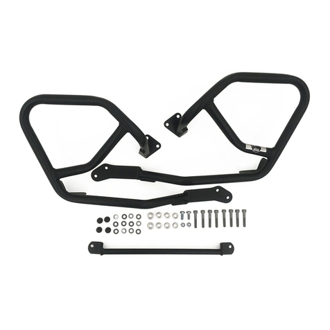
hepco & becker 5024564 00 01 User manual

hepco & becker

hepco & becker 5024564 00 01 User manual

hepco & becker 6264538 00 01 User manual

hepco & becker

hepco & becker 6264538 00 01 User manual

hepco & becker 650642 00 01 User manual

hepco & becker

hepco & becker 650642 00 01 User manual

hepco & becker 653554 00 01 User manual

hepco & becker

hepco & becker 653554 00 01 User manual

hepco & becker 6503534 00 01 User manual

hepco & becker

hepco & becker 6503534 00 01 User manual

hepco & becker 630952 00 01 User manual

hepco & becker

hepco & becker 630952 00 01 User manual

hepco & becker Easyrack 6614526 01 01 User manual

hepco & becker

hepco & becker Easyrack 6614526 01 01 User manual

hepco & becker 6503516 01 02 User manual

hepco & becker

hepco & becker 6503516 01 02 User manual

hepco & becker SPORTRACK 670915 00 01 User manual

hepco & becker

hepco & becker SPORTRACK 670915 00 01 User manual

hepco & becker 6302539 00 01 User manual

hepco & becker

hepco & becker 6302539 00 01 User manual

hepco & becker Sportrack 670701 00 01 User manual

hepco & becker

hepco & becker Sportrack 670701 00 01 User manual

hepco & becker 6302516 00 01 User manual

hepco & becker

hepco & becker 6302516 00 01 User manual

hepco & becker 630665 0001 User manual

hepco & becker

hepco & becker 630665 0001 User manual

hepco & becker 6537543 00 01 User manual

hepco & becker

hepco & becker 6537543 00 01 User manual

hepco & becker 8007593 00 01 User manual

hepco & becker

hepco & becker 8007593 00 01 User manual

hepco & becker 502994 00 01 User manual

hepco & becker

hepco & becker 502994 00 01 User manual

hepco & becker 6507513 00 01 User manual

hepco & becker

hepco & becker 6507513 00 01 User manual

hepco & becker 701998 00 01 User manual

hepco & becker

hepco & becker 701998 00 01 User manual

hepco & becker 506.003-6 User manual

hepco & becker

hepco & becker 506.003-6 User manual

hepco & becker 8007581 00 01 User manual

hepco & becker

hepco & becker 8007581 00 01 User manual

hepco & becker 4212999 00 01 User manual

hepco & becker

hepco & becker 4212999 00 01 User manual

hepco & becker Easyrack User manual

hepco & becker

hepco & becker Easyrack User manual

hepco & becker 5017571 0002 User manual
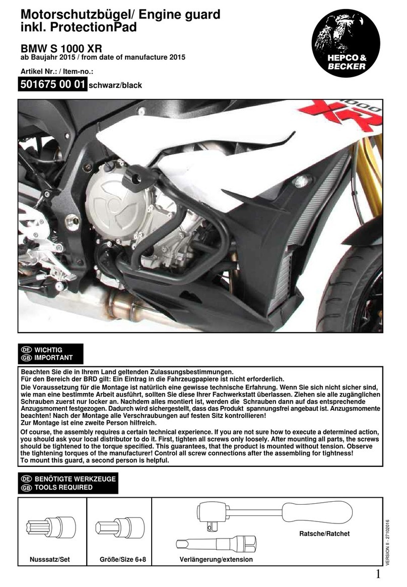
hepco & becker

hepco & becker 5017571 0002 User manual

hepco & becker 5014568 00 01 User manual

hepco & becker

hepco & becker 5014568 00 01 User manual

Popular Motorcycle Accessories manuals by other brands

SRC H-ADV150-04-01AL quick start guide

SRC

SRC H-ADV150-04-01AL quick start guide

DMD P1 owner's manual

DMD

DMD P1 owner's manual

GIVI Airflow AF1110 manual

GIVI

GIVI Airflow AF1110 manual

Suzuki 99143-00A1 000 Series installation instructions

Suzuki

Suzuki 99143-00A1 000 Series installation instructions

Cardo Systems FREECOM 4+ Pocket guide

Cardo Systems

Cardo Systems FREECOM 4+ Pocket guide

Shark S 700 user manual

Shark

Shark S 700 user manual

R&G CR0081 Fitting instructions

R&G

R&G CR0081 Fitting instructions

SRC B-TRK502-01-01-SL quick start guide

SRC

SRC B-TRK502-01-01-SL quick start guide

HOMCOM AA0-077 user manual

HOMCOM

HOMCOM AA0-077 user manual

SHOEI JO Instructions for use

SHOEI

SHOEI JO Instructions for use

Wunderkind Custom 106503-F15 Installation and safety

Wunderkind Custom

Wunderkind Custom 106503-F15 Installation and safety

Suzuki 57100-05881 installation instructions

Suzuki

Suzuki 57100-05881 installation instructions

SIKH HELMETS Y-61 quick start guide

SIKH HELMETS

SIKH HELMETS Y-61 quick start guide

Dräger HPS 3500 Instructions for use

Dräger

Dräger HPS 3500 Instructions for use

M-WAVE SKI manual

M-WAVE

M-WAVE SKI manual

Kuryakyn 6212 installation instructions

Kuryakyn

Kuryakyn 6212 installation instructions

Tool it PROMAX LCD 9.13G manual

Tool it

Tool it PROMAX LCD 9.13G manual

Custom Dynamics TruWrapz installation instructions

Custom Dynamics

Custom Dynamics TruWrapz installation instructions

manuals.online logo
manuals.online logoBrands
  • About & Mission
  • Contact us
  • Privacy Policy
  • Terms and Conditions

Copyright 2025 Manuals.Online. All Rights Reserved.