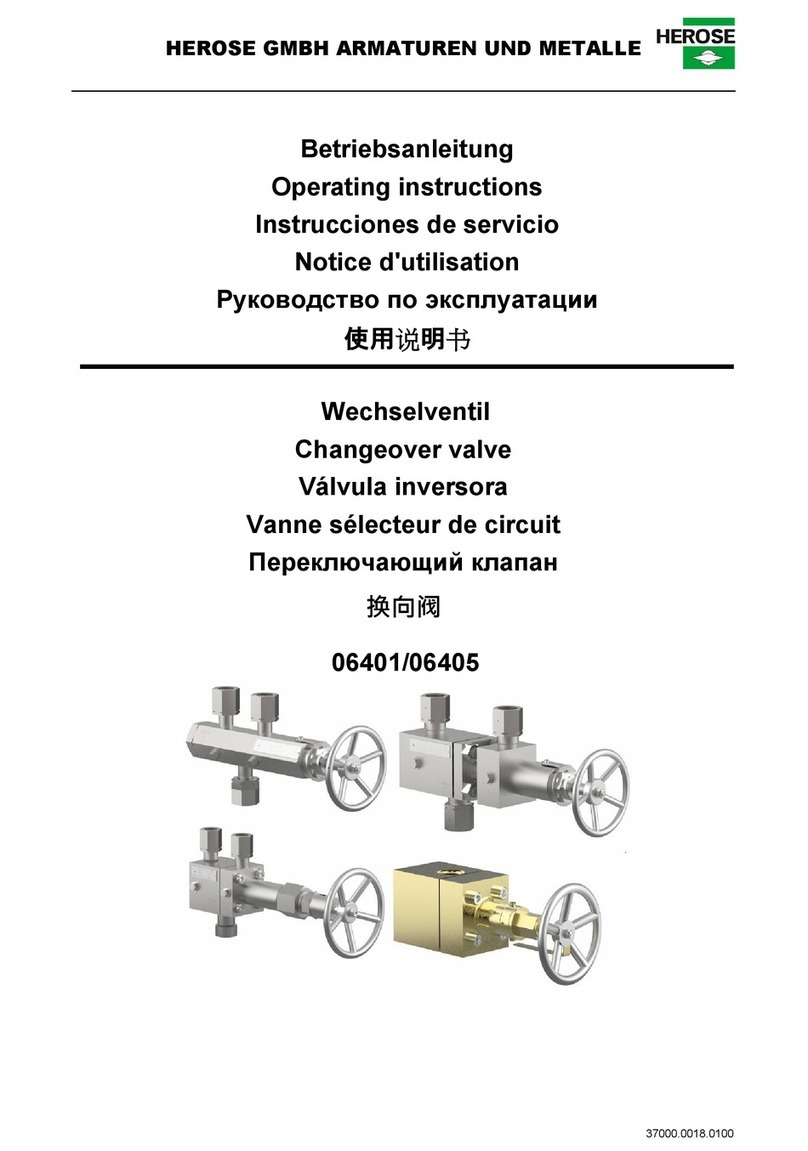
HEROSE 01312 User manual

HEROSE GMBH ARMATUREN UND METALLE
Operating instructions
Cryogenic Globe valves
- Angle type -


Operating instructions
herose.com
I
READ CAREFULLY BEFORE USE! RETAIN FOR FUTURE REFERENCE!
© 2019 HEROSE GMBH
ARMATUREN UND METALLE
Elly-Heuss-Knapp-Straße 12
23843 Bad Oldesloe
Germany
Phone: +49 4531 509 –0
Fax: +49 4531 509 –120
Web: www.herose.com
2nd issue 07/2019
The transmission or duplication of this document and the use or communication of its
content are forbidden unless expressly permitted. Any violations shall result in liability for
damages. All rights in the event of patent, utility model or registered design are
reserved.

Operating instructions
II
Phone +49 4531 509-0
Table of contents
1About these instructions .................................................................................................. 1
2Safety .............................................................................................................................. 1
3Transport and storage ..................................................................................................... 4
4Description of the angle valve ......................................................................................... 4
5Assembly......................................................................................................................... 7
6Operation ...................................................................................................................... 10
7Maintenance and service .............................................................................................. 11
8Disassembly and disposal............................................................................................. 13

Operating instructions
herose.com
1
1 About these instructions
1.1 Principles
The operating instructions are part of the angle valve named on the front page.
1.2 Applicable documents
Document
Contents
Catalogue page
Description of the angle valve
For accessories, refer to the respective manufacturer's documentation.
1.3 Hazard levels
The warning notes are marked and classified according to the following hazard levels:
Symbol
Explanation
DANGER
Identifies a hazard with a high risk level that will result in death
or serious injury.
WARNING
Identifies a hazard with a moderate risk level that will result in
death or serious injury.
CAUTION
Identifies a hazard with a low risk level that will result in a minor
or moderate injury.
NOTICE
Identifies a risk to property. Damage to property may occur if
this notice is ignored.
2 Safety
2.1 Intended use
The angle valve is intended for mounting in a pipeline or pressure tank system in order to block media or
allow them to pass through within the permissible operating conditions. The permissible operating
conditions are specified in these operating instructions.
The angle valve is suitable for the media listed in these operating instructions; see section 4.5 "Media".
Operating conditions and applications deviating from these require the approval of the manufacturer.
Only media may be employed to which the materials used for the valve body and seals are resistant.
Contaminated media or usage outside of the pressure and temperature specifications can lead to damage
to the valve body and seals.
Avoidance of foreseeable incorrect use
Never exceed the permissible usage limits specified in the data sheet or in the documentation
with regard to pressure, temperature, etc.
Follow all safety instructions and operating procedures in these operating instructions.
2.2 Meaning of the operating instructions
The operating instructions are to be read and followed by the responsible technical personnel before
mounting and start-up. As part of the angle valve the operating instructions must be available close to it.
People could be seriously injured or killed if the operating instructions are not followed.
Read and observe the operating instructions before using the angle valve.
Retain the operating instructions and make sure they are available.
Pass on the operating instructions to subsequent users.

Operating instructions
2
Phone +49 4531 509-0
2.3 Requirements for persons who work with the angle valve
Persons could be seriously injured or killed if the angle valve is used improperly. In order to avoid
accidents, all persons who work with the angle valve must meet the following minimum requirements.
They are physically capable to control the angle valve.
They can safely carry out the work with the angle valve within the scope of these operating
instructions.
They understand the operating principles of the angle valve within the scope of their work and are
able to recognise and avoid the hazards of the work.
They have understood the operating instructions and are able to implement the information of the
operating instructions accordingly.
2.4 Personal protective equipment
Missing or unsuitable personal protective equipment increases the risk of damage to health and injuries to
people.
The following protective equipment is to be provided and worn during work:
Protective clothing
Safety shoes
Define and use additional protective equipment depending on the application and the media:
Safety gloves
Eye protection
Ear protection
Wear the specified personal protective equipment for all work on the angle valve.
2.5 Additional equipment and spare parts
Additional equipment and spare parts not conforming to the manufacturer's requirements can negatively
affect the operational safety of the angle valve and cause accidents.
In order to ensure operational safety, use original parts or parts that conform to the
manufacturer's requirements. If in doubt, have these confirmed by the dealer or manufacturer.
2.6 Adhere to the technical thresholds
If the technical threshold values are not adhered to, the angle valve may sustain damage, accidents may
be caused and people may be seriously injured or killed.
Adhere to the thresholds. See section “4 Description of the angle valve”.
2.7 Safety instructions
DANGER
Hazardous medium.
Escaping operating medium can lead to poisoning, burns and caustic burns!
Wear the prescribed protective equipment.
Provide suitable collecting containers.
WARNING
Harmful and/or hot/cold conveyed media, lubricants and fuels.
Hazardous for persons and the environment!
Collect and dispose of rinsing medium and any residual media.
Wear protective clothing and a protective mask.
Observe legal regulations regarding the disposal of harmful media.
Risk of injury if maintenance work is done incorrectly.
Incorrect maintenance can lead to serious injury and considerable material damage!
Before the start of work, ensure there is sufficient room for doing the work.
Ensure the space around the work is tidy and clean! Parts and tools in loose piles or lying around
are hazard sources.
If parts have been removed, take care to assemble correctly and re-install all attachment items.
Before putting back into service, ensure:
All maintenance work has been carried out and completed.
There are no persons in the hazard area.
All covers and safety devices are installed and operating correctly.

Operating instructions
herose.com
3
CAUTION
Cold/hot pipelines and/or angle valves.
Risk of injury due to thermal influences!
Insulate the angle valve.
Attach warning signs.
Medium escaping at high speed and high/low temperature.
Risk of injury!
Wear the prescribed protective equipment.
NOTICE
Impermissible stresses arising from operating conditions and extensions / added structures.
Angle valve body leaking or broken!
Provide suitable support.
Additional loads, such as traffic, wind or earthquakes, are not explicitly taken into account by
default and require separate sizing.
Condensation in air conditioning, cooling and refrigeration plants.
Icing!
Blocking of the actuation mechanism!
Damage due to corrosion!
Insulate the angle valve with diffusion-tight material.
Improper handling.
Leak or damage to the angle valve!
Do not store tools and/or other objects on the angle valve.
Do not use tools to increase the torque of the hand wheel.
Painting of the angle valve and pipelines.
Functional impairment of the valve / loss of information!
Protect stem, plastic parts and type plate against the application of paint.
Impermissible stress
Damage to the control mechanism!
Do not use the angle valve as a foothold.
Exceeding the maximum permissible operating conditions.
Damage to the angle valve!
The maximum permissible operating pressure must not be exceeded, and the minimum and
maximum allowable working temperatures must be observed.
Create the welding/soldering seam stepwise so that the warming in the middle of the body does
not exceed the maximum permissible operating temperature.
Welding beads, scale and other contaminants.
Damage to the angle valve!
Take appropriate measures against contamination.
Remove contaminants from the pipes.
Incorrect earthing during welding work in the pipeline.
Damage to the angle valve (burned spots)!
Remove bonnet during welding.
When carrying out electric welding work, do not use functional parts of the angle valve for
earthing.

Operating instructions
4
Phone +49 4531 509-0
3 Transport and storage
3.1 Inspection of condition on delivery
Inspect the angle valve for damage upon receipt.
In case of transport damage, determine and document the precise extent of the damage, and
report it immediately to the supplying dealer/carrier and the insurer.
3.2 Transportation
Transport the angle valve in the packaging supplied.
The angle valve is delivered ready to operate with lateral connections protected by cover caps.
Protect the angle valve against hammering, impacts, vibrations and dirt.
Adhere to a transport temperature range of -20 °C to +65 °C.
3.3 Storage
Store the angle valve in a clean and dry place.
Make use of a desiccant or heating in damp storerooms to prevent the formation of
condensation.
Adhere to a storage temperature range of -20 °C to +65 °C.
4 Description of the angle valve
Refer to the respective catalogue page for further detailed information.
4.1 Structure
Design
Non-automatically opening and closing gate valve angle type.
Component
Design
Body
Angle type
Bonnet
Flanged, internal spindle thread
Operating mechanism
Rising stem
Obturator
Disc with seal made of non-metallic materials
Stem bushing
Non self-sealing, packing gland
Body end
with soldering end
with welding end
with threaded end (G; R; NPT; M)
with welded-in/soldered-in pipes
4.2 Valving marking
The angle valves are provided with an individual marking for identification.
Symbol
Explanation
DN…..
Nominal diameter
PN…..
Rated working pressure (max. permissible operating
pressure)
-…..°C +…..°C
Temperature
Manufacturer’s mark “HEROSE”
01/18
Year of construction MM/YY
12345
Type
01234567
Serial no.
EN1626
Standard
0045
CE-mark and number of the notified body
0045
PI-mark and number of the notified body
e.g. CF8 / 1.4308
Material

Operating instructions
herose.com
5
4.3 Intended use
Angle valves are used for shutting off and/or throttling media.
Install angle valves so that the stem is vertical and the type of the
medium enters under the cone.
The angle valve is opened or closed by turning the handwheel or
actuating the actuator. Tools for increasing handwheel torque are
not allowed.
Detailed installation instructions for the actuator are included for
angle valves with pneumatic or electric actuator-unit.
4.4 Operational data
Valve
Nominal
pressure
Permissible
operating
temperature
Recommended
operating
temperature
Max. operating
pressure
01312
PN50
-196 °C to +120 °C
-
50 bar
01322
PN50
-196 °C to +120 °C
-
50 bar
01332
PN50
-196 °C to +120 °C
-60 °C to +120 °C
50 bar
01342
PN50
-196 °C to +120 °C
-
50 bar
01346
PN50
-196 °C to +120 °C
-
50 bar
01352
PN50
-196 °C to +120 °C
-60 °C to +120 °C
50 bar
4.5 Media
Gases, cryogenic liquefied gases and their gas mixtures, such as:
Name
Argon,
Chlorotrifluoromethane,
Nitrous oxide,
Ethane,
Ethylene,
Carbon dioxide,
Carbon monoxide
Krypton,
LNG
LPG
Methane,
Oxygen,
Nitrogen,
Trifluoromethane,
Close
Open

Operating instructions
6
Phone +49 4531 509-0
4.6 Materials
Part
no.
Name
Material
1
Handwheel
Aluminium alloy
2
Stem
1.4301; 1.4305
3
Screws
A2 –70
4
Bonnet
CC493K; 1.4301; 1.4308
5
Obturator
CW614N; 1.4301; Hostaflon TF4215; TFM 1600;
TFM 1700
6
Body
1.4308 (CF8); CC491K
4.7 Scope of delivery
Valve
Operating instructions
4.8 Dimensions and weights
See catalogue page.
4.9 Lifetime
The user is obligated to use Herose products only for their intended purpose.
In this case, a technical service life may be assumed in accordance with the underlying product standards
(e.g. EN1626 for shut-off valves and EN ISO 4126-1 for safety valves).
The technical service life can be restarted several times through the exchange of wearing parts within the
context of the maintenance intervals, and lifetimes of more than 10 years can be achieved.
If products are stored for a period exceeding 3 years, then the plastic components and elastomer sealing
elements fitted to the product should be replaced as a precautionary measure before mounting and use.
1
2
3
4
5
6

Operating instructions
herose.com
7
5 Assembly
5.1 Installation position
With regard to the installation position, pay attention to the arrow showing the flow direction. When
installing the angle valve in a horizontal pipeline, a vertical position of the stem is recommended
(handwheel at the top) or an inclination of up to 65° from the vertical.
5.2 Notices regarding the mounting
Use suitable tools.
Allen keys of sizes 6, 8 and 10;
Open-ended spanners;
Torque wrench;
TIG welding machine;
Oxy-fuel welding machine;
Clean tools before the mounting.
Use suitable transport and lifting equipment for the mounting.
Open the packaging only directly before the mounting. Free from oil and grease for oxygen (O2)
Angle valves for oxygen are permanently labelled with “O2”.
Only install the angle valve if the maximum operating pressure and operating conditions of the
plant correspond to the marking on the valve.
Remove protective caps or covers before mounting.
Check the angle valve for dirt and damage.
DO NOT install a damaged or dirty angle valve.
Avoid damaging the connections.
The sealing surfaces must remain clean and intact.
Seal the angle valve with suitable seals.
No sealant (sealing tape, liquid sealing tape) may enter the angle valves.
Respect the suitability for use with O2.
Connect pipelines in a force-free and torque-free manner.
Stress-free mounting.
In order to ensure trouble-free operation, no impermissible static, thermal or dynamic stresses
may be transmitted to the angle valve. Observe reaction forces.
Temperature-dependent changes in length in the pipework system must be compensated with
expansion joints.
The angle valve is supported by the pipework system.
Detailed installation instructions are included for angle valves with pneumatic or electric actuator-
unit.
Driven angle valves: Mounting/dismounting the bonnet in the centre position of the actuator.
The angle valve must be protected against dirt and damage during construction work.
Remove any transport locks such as blocking bushing (optional).
Check the leak-tightness.

Operating instructions
8
Phone +49 4531 509-0
5.3 Welding / soldering
Welding / soldering of the angle valves and any heat treatment that may be required are the responsibility
of the contracting construction company or operating company.
Before welding / soldering
Loosen the screws
Direction of rotation: counter
clockwise
Remove the screws
Remove bonnet and seal
Dispose of the seal
Weld / solder in the body

Operating instructions
herose.com
9
After welding / soldering
Insert a new seal
Assemble the bonnet
Do not damage the seal
Assemble the screws
Tighten the screws to the specified
tightening torque in a criss-cross
pattern
Direction of rotation: clockwise

Operating instructions
10
Phone +49 4531 509-0
Assembly sequence for the bolts
Nominal
diameter
Gun-
metal-
bonnet/
Gun-
metal-
body
[Nm]
Gun-
metal-
bonnet/
VA-body
[Nm]
VA-
bonnet/
VA-
body
[Nm]
Cap bolt
DN 10
19
19
25
30
M8
DN 15
19
19
25
30
M8
DN 20
37
44
50
M10
DN 25
37
44
50
M10
DN 32
41
45
50
M10
DN 40
51
60
70
M12
DN 50
49
50
50
M10
Bonnet / body tightening torques
Check the leak-tightness
6 Operation
6.1 Prior to start-up
Check the following points prior to start-up:
All mounting and installation work are completed.
If fitted: The blocking bushing was removed prior to start-up.
The safety guards are in place.
Compare the material, pressure, temperature and installation position with the layout plan for
the pipework system.
Dirt and residues have been removed from the pipeline and valve in order to prevent leaks.

Operating instructions
herose.com
11
7 Maintenance and service
7.1 Safety during cleaning
Take note of the specifications in the safety data sheet and the general occupational health and
safety rules if degreasers are used for process-related reasons for the cleaning of bearing parts,
unions and other precision parts.
7.2 Maintenance
The maintenance intervals must be defined by the user according to the operating conditions.
The recommendations for the functional checking of the angle valves are to be taken from section 7.2.1
"Inspection and maintenance intervals" in these operating instructions.
7.2.1 Inspection and maintenance intervals
Recommended intervals
Description
Interval
Scope
Inspection
During start-up
Visual inspection
of the angle valve for damage;
of the valving marking for
legibility;
Installation position;
Leak-tightness
at the gland packing;
between bonnet and body;
of the valve seat;
Test the opening and closing
functions of the angle valve.
Functional testing
Annually
Test the opening and closing
functions of
the angle valve including a visual
inspection.
External inspection
Every 2 years
Function and tightness test
including visual check.
Internal inspection
Every 5 years
Replacement of all sealing
elements, including a function and
tightness test as well as a visual
inspection.
Hydraulic testing
Every 10 years
Replacement of all sealing
elements, including a function, leak
and pressure test as well as an
inspection.

Operating instructions
12
Phone +49 4531 509-0
7.3 Fault table
Fault
Cause
Remedial action
Leak at the stem
Gland nut loose
Retighten the gland nut
Gland packing defective
Replace the gland packing
Fit on the stem damaged
Replace the stem
Leak between bonnet
and body
Bonnet loose
Tighten the screws to the specified
tightening torque
Seal damaged
Replace seal
Leak in the seating
Foreign body between cone
and seating
Remove foreign body / flush the
system
Seating damaged
Replace the body
Cone seal damaged
Replace the cone
Body leaking
Discontinuity/gas cavity open
Replace the body
Angle valve does not
open / close
Gland nut overtightened
Loosen the gland nut
Tightness must still be ensured
Thread seized
Replace bonnet
Actuator not working
Check supply of energy to the
actuator
Check limit switches
7.4 Spare parts
We require the following details for your spare part orders:
article no. of the spare part package,
desired delivery quantity,
dispatch and delivery address,
desired method of dispatch.
7.5 Returns / complaints
Use the Service form in case of returns/complaints.
Contact in case of service:
Herose.com › Service › Product service › Complaints
Fax: +49 4531 509 –9285

Operating instructions
herose.com
13
8 Disassembly and disposal
8.1 Notices regarding the disassembly
Take note of all national and local safety requirements.
The pipework system must be depressurised.
The medium and valve must be at ambient temperature.
Aerate / flush the pipework system in the case of corrosive and aggressive media.
8.2 Disposal
1. Dismount the valves.
Collect greases and lubricating fluids during dismantling.
2. Separate the valve materials:
Metal
Synthetic material
Electronic scrap
Greases and lubricating fluids
3. Carry out a sorted disposal of the materials.

Operating instructions
14
Phone +49 4531 509-0
Other manuals for 01312
2
This manual suits for next models
5
Table of contents
Other HEROSE Control Unit manuals
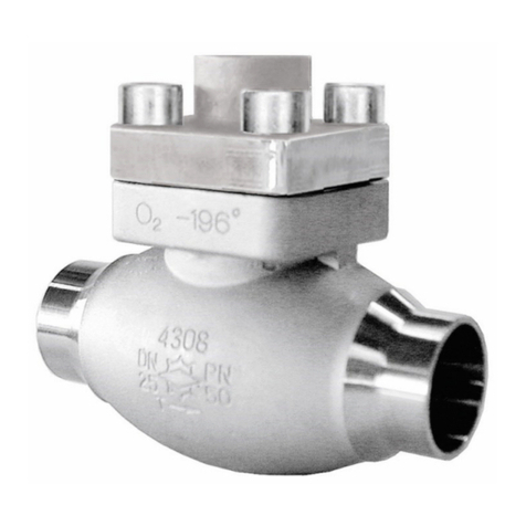
HEROSE
HEROSE 05411 User manual

HEROSE
HEROSE 0653X User manual
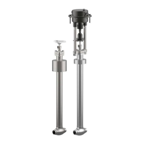
HEROSE
HEROSE 0142 Series User manual

HEROSE
HEROSE 0651X User manual
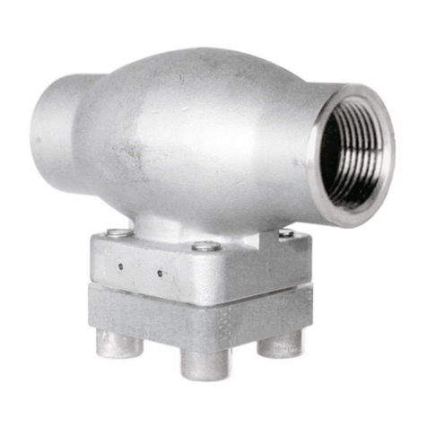
HEROSE
HEROSE 08411 User manual
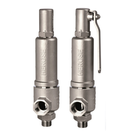
HEROSE
HEROSE 0681 Series User manual

HEROSE
HEROSE 0681 Series User manual
HEROSE
HEROSE 093 Series User manual

HEROSE
HEROSE 093 Series User manual
HEROSE
HEROSE 06001 User manual

HEROSE
HEROSE 06001 User manual
HEROSE
HEROSE 7111 User manual
HEROSE
HEROSE 15C02 User manual

HEROSE
HEROSE 08411 User manual

HEROSE
HEROSE 03021 User manual
HEROSE
HEROSE 0651 Series User manual

HEROSE
HEROSE 01312 User manual

HEROSE
HEROSE 0651 Series User manual
HEROSE
HEROSE 15C01 User manual

HEROSE
HEROSE 7111 User manual
