Highlight MAGNUM 1300 TB-U User manual
OPERATION MANUAL
MAGNUM 1300 TB-U
UNIFORM CASE SEALER
SERIAL NUMBER
Please refer to the serial number in all correspondence with Highlight or any Highlight
Distributor. This identifies your machine and will help in our ability to quickly and
efficiently respond to your needs.
Version 1.4 – May 2011

MAGNUM 1300 TB-U UNIFORM CASE SEALER OPERATION MANUAL
HIGHLIGHT INDUSTRIES, INC. * 2694 PRAIRIE SW; GRAND RAPIDS; MI 49519 * 1-800-531-2465
TABLE OF CONTENTS
1. General System Information
1. System Specifications ……………………………………………………………………...I-1
2. System Overview Prints.…..……………………………………………………………… I-2
3. System Descriptions…..……………………..…………………………….……………….I-3
4. Tape Head and Tape Overview Prints……………………………………………..…….I-4
5. Tape Head Descriptions………………………………………………………………..…. I-5
6. Tape Threading Diagram……………………………………………………………….… I-6
7. Limited Warranty.…………………………………………………………………………. I-7
2. Installation Instructions
1. Safety Precautions…………...…………………………………………………………….. II-1
2. Machine Placement.……………………..………………………………………………… II-2
3. Machine Set-Up……………………………………………………………………………..II-3
3. Operation Instructions
1. Safety Precautions…………...…………………………………………………………….. III-1
2. Pre-Operation Adjustments…………...………………………………………………….. III-2
3. Touch Screen Operator Controls……………...………………………………………......III-8
4. Machine Operations……………………………………………………………………… III-9
4. Maintenance
1. Preventive Maintenance…………...……………………………………………………… IV-1
5. Troubleshooting
1. Troubleshooting Guide…………………………………………………………………….V-1
6. Electrical References
1. Electrical Parts List and Prints……………………………………………….……………VI-1
7. Mechanical References
1.Mechanical Parts List and Prints…………………………………………………….…….VII-1
8. Notes

MAGNUM 1300 TB-U UNIFORM CASE SEALER OPERATION MANUAL
HIGHLIGHT INDUSTRIES, INC. * 2694 PRAIRIE SW; GRAND RAPIDS; MI 49519 * 1-800-531-2465
I. Chapter 1
HIGHLIGHT INDUSTRIES, INC.
Magnum®1300 TB-U Uniform Case Sealer Operation Manual
General System
Information
Chapter
1

SYSTEM SPECIFICATIONS
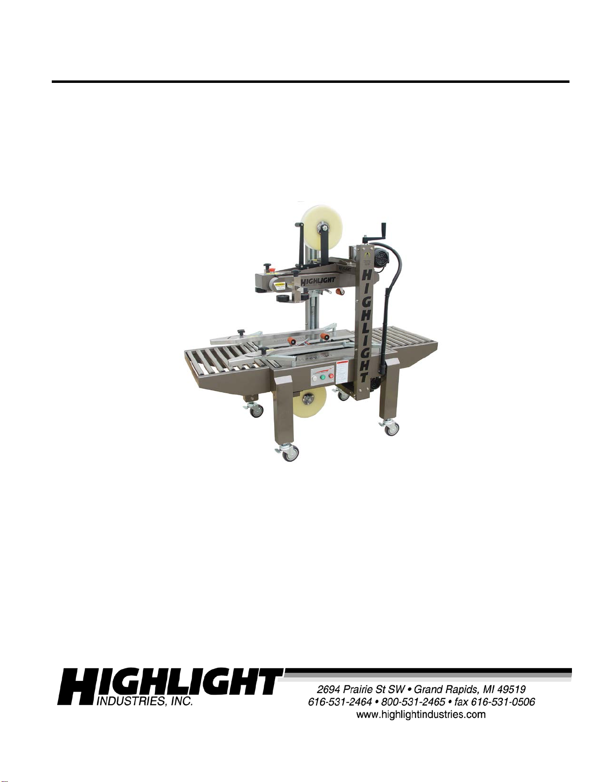
Highlight Industries’ Magnum® 1300 TB-U is an adjustable top and bottom belt drive
case sealer designed to provide accurate, consistent tape application to uniform cases.
Highlight Industries’ 200 series tape head will accept any 2-inch case tape and provide
optimum case sealing to the top and bottom of the case. The system is designed to
operate at up to 30 cases per minute. Stainless steel 16-inch long entry and exit
conveyors are standard. Height adjustable legs from 22 inches to 32 inches with locking
casters included.
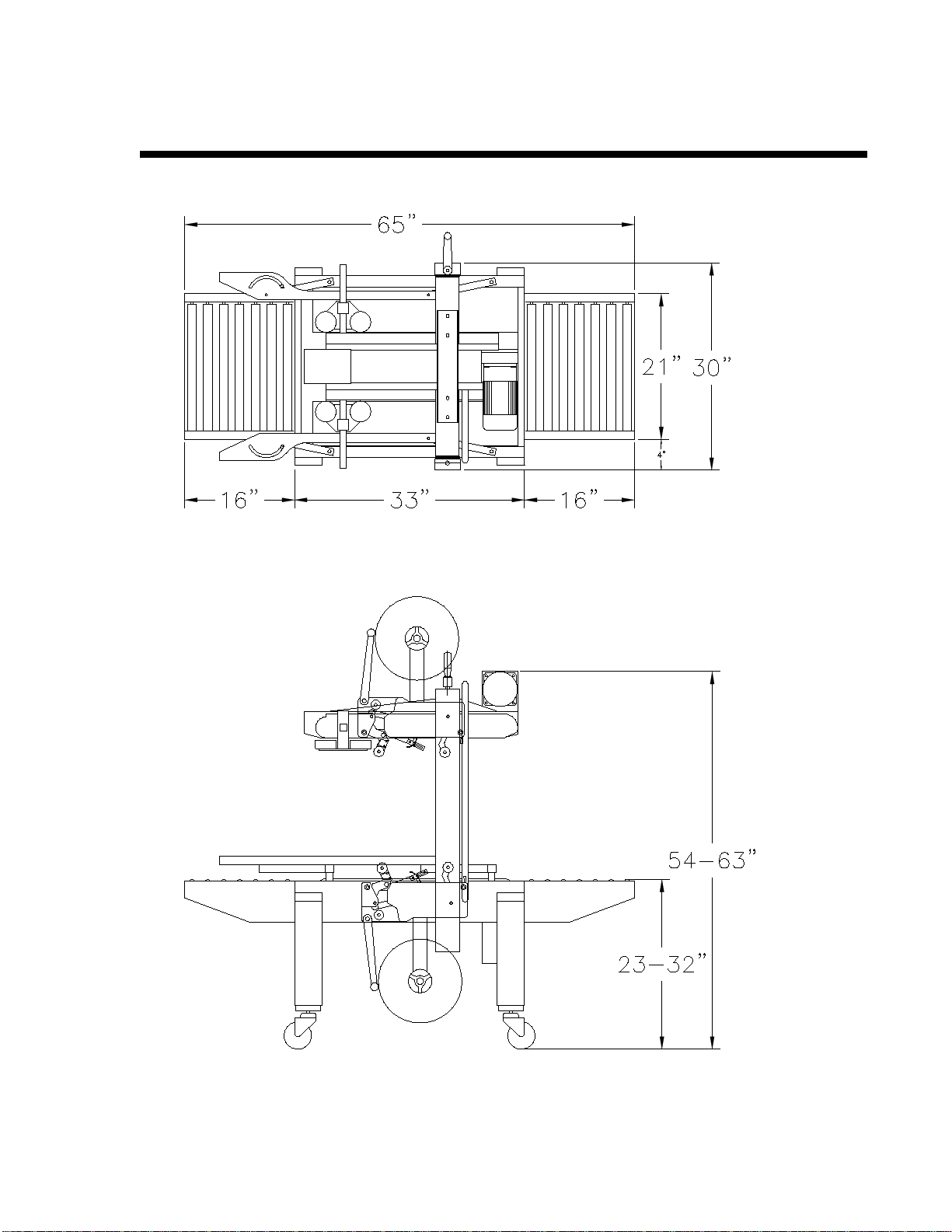
Machine Size
o64” L x 30” W x 54” H (with 16” L Entry Conveyor and 16”L Exit
Conveyor, 36” L without)
oShipping weight – 375 lbs on a pallet
oTape Roll Diameter: 3” inside diameter core with up to 16” outside
diameter
oTape Roll Width: 1 ½” and 2” tape standard
Operation Space
o75” L x 45” W x 70” H
Electrical Data
o120 VAC; Single Phase, 10 Amps, 60 Hz
Production Capacity
oOperating Rate: Up to 30 boxes per minute depending on box length
oCase Belt Speed: 75 feet per minute
oMinimum Load Size: 5” L x 5.5” W x 5” H
oMinimum Load Weight: 4 lbs
oMaximum Load Size: 20” W x 20” H
oMaximum Load Weight: 75 lbs
SYSTEM OVERVIEW PRINTS

SYSTEM DESCRIPTIONS

TAPE HEAD & TAPE OVERVIEW PRINTS
2”W Tape 3”W Tape 2” Tape Legs / 15.25”L Frame – REGULAR DUTY
***Tape heads w/ 2” tape legs are suited for general duty applications ***
3”W Tape 3” Tape Legs / 17.2”L Frame – HEAVY DUTY BOXES
***This head w/ 3” tape legs is for heavy-duty, double wall, or firm-packed cartons only***

TAPE HEAD DESCRIPTIONS

TAPE THREADING DIAGRAM
NOTE:
Be sure EMERGENCY STOP button is pushed in before
threading the tape and pulled out when tape is threaded.

LIMITED WARRANTY
Highlight Industries, Inc. warrants that its case sealers will be of merchantable quality, free from
defects in material and workmanship as determined at the date of shipment, by generally
recognized, applicable and accepted practices and procedures in the industry, for a period of:
1. The taping head knife blades, springs and rollers are warranted for ninety (90) days
2. All other taping head parts are warranted for three (3) years
3. All other parts of the Highlight case tapers are warranted for two (2) years
from the Highlight invoice date, under normal use and service.
When the Purchaser gives Highlight written notice of any alleged defect within the applicable
warranty period, Highlight will, at its option, repair or replace the same free of charge F.O.B. its
manufacturing plant, installation not included. Equipment replaced under the warranty shall
have the same warranty as new equipment but does not extend the warranty of the original
equipment.
Satisfaction of this warranty, consistent with other provisions herein, will be limited to the
replacement or repair or modification of, or issuance of a credit for, the equipment involved, at
Highlight’s option.
Highlight neither assumes nor authorizes any person to assume for it any other obligation in
connection with the sale of Highlight’s equipment.
This warranty shall not apply to any equipment which has been repaired or altered by un-
authorized personnel in any way so as to, in the judgment of Highlight, affect serviceability, or
which has been subjected to misuse, negligence, accident, or to equipment made by Highlight
which has been operated in a manner contrary to Highlight’s instructions.
In no event regardless of the cause, shall Highlight be liable for penalties or penalty clauses of
any description or any damages resulting from loss of profits, use of products or for any
incidental indirect or consequential damages, even if advised of the possibility of such damages.
This limitation of Highlight’s liability will apply regardless of the form of action, whether in
contract or tort, including negligence. Any action against Highlight must be brought within
twelve (12) months after cause of action accrues.
“THIS WARRANTY IS IN LIEU OF ALL OTHER WARRANTIES WHETHER EXPRESSED,
IMPLIED OR STATUTORY INCLUDING IMPLIED WARRANTIES OF MERCHANTABILITY
OF FITNESS AND EXTENDS ONLY TO THE BUYER OR CUSTOMER PURCHASING FROM
HIGHLIGHT OR AN AUTHORIZED HIGHLIGHT DISTRIBUTOR.”

MAGNUM 1300 TB-U UNIFORM CASE SEALER OPERATION MANUAL
HIGHLIGHT INDUSTRIES, INC. * 2694 PRAIRIE SW; GRAND RAPIDS; MI 49519 * 1-800-531-2465
II. Chapter 2
HIGHLIGHT INDUSTRIES, INC.
Magnum®1300 TB-U Uniform Case Sealer Operation Manual
Installation
Instructions
Chapter
2

SAFETY PRECAUTIONS
•Read the Operation Manual before operating the machine.
•Do NOT attempt to service the machinery unless you are qualified and understand
the Operations Manual.
•Do NOT use extension cords to operate the system.
•Make sure nothing is on the power cable.
•Make sure nothing is on the upper tape head unit.
•Loose clothing must NOT be worn while the machine is in operation.
•Stay clear of moving parts while the machine is in operation.
•Do NOT allow dampness or water to enter the electrical units.
•Turn OFF power to the machine when it is not in use.
•NEVER try to remove jammed boxes from the machine while it is running.
•When feeding boxes manually, push boxes into drive belts using the end of the box,
not with your hands on any corner of the box.
•Both tape heads use EXTREMELY SHARP knives! The orange guard is labeled.
Know the knife’s location BEFORE attempting to load and thread tape, or to make
any tape head adjustments.
SEVERE PERSONAL INJURY AND/OR EQUIPMENT DAMAGE could result from
failure to comply with the above.

MACHINE PLACEMENT
Inspections
Before installation, inspect the entire machine for visual damage. If found, please report
this damage to the truck line. Highlight Industries has taken every precaution during the
packaging and loading of this equipment. However, it is YOUR RESPONSIBILITY to
inspect for damage before installation.
Positioning of the Machine
Place your Magnum® Case Sealer close to an area where you will be sealing your loads.
Make sure that there is sufficient room to load/unload the machine and that you do not
stretch the wiring cable. Remember, you will need to provide electrical service to a 120
VAC, 10 Amp-outlet. DO NOT USE EXTENSION CORDS!!
Floor Weight Bearing/Stress Tolerance
The floor must be able to bear the weight of the machine, plus the weight of the
maximum load, which is 75 lbs, plus a safety factor. The floor must also be able to
tolerate the stress of the machine’s operation.

MACHINE SET-UP
It is very important to read all instructions before undertaking any of these steps. The
following steps should help achieving a safe and quick machine set-up.
1. Your Magnum® Case Sealer comes pre-assembled and ready for operation. Set
up the machine where it will not be subject to moisture or damage to its power
cord.
2. Although the Magnum® Case Sealer is pre-assembled, the casters allow for some
height adjustment. To adjust height, loosen “B” screw on all four casters (see
figure below), lift machine to desired height and retighten “B” screw.
NOTE: Nut “A” fixes the caster in place.
3. The rollers are detachable. They are held to the machine by four holding screws
attached to the machine body. To detach the roller tables, loosen (complete
removal is not necessary) all four holding screws, then lift the table straight up
and pull out. The table has four slots fitting over the screws (see figure below).

MAGNUM 1300 TB-U UNIFORM CASE SEALER OPERATION MANUAL
HIGHLIGHT INDUSTRIES, INC. * 2694 PRAIRIE SW; GRAND RAPIDS; MI 49519 * 1-800-531-2465
III. Chapter 3
HIGHLIGHT INDUSTRIES, INC.
Magnum®1300 TB-U Uniform Case Sealer Operation Manual
Operation
Instructions
Chapter
3

SAFETY PRECAUTIONS
•Read the Operation Manual before operating the machine.
•Do NOT attempt to service the machinery unless you are qualified and understand
the Operations Manual.
•Do NOT use extension cords to operate the system.
•Make sure nothing is on the power cable.
•Make sure nothing is on the upper tape head unit.
•Loose clothing must NOT be worn while the machine is in operation.
•Stay clear of moving parts while the machine is in operation.
•Do NOT allow dampness or water to enter the electrical units.
•Turn OFF power to the machine when it is not in use.
•NEVER try to remove jammed boxes from the machine while it is running.
•When feeding boxes manually, push boxes into drive belts using the end of the box,
not with your hands on any corner of the box.
•Both tape heads use EXTREMELY SHARP knives! The orange guard is labeled.
Know the knife’s location BEFORE attempting to load and thread tape, or to make
any tape head adjustments.
SEVERE PERSONAL INJURY AND/OR EQUIPMENT DAMAGE could result from
failure to comply with the above.

PRE-OPERATION ADJUSTMENTS
BELT ADJUSTMENT AND REPLACEMENT
Adjustment
Press the Emergency Stop switch and unplug the machine electrical cord. For upper
belts, remove E-Stop cover plate. For lower belts, remove small cover plate (#8 on VII-4)
in front of bottom tape head. Loosen jam nuts (A) & (B) and adjust the belts to a suitable
tension using jam nuts (B). Be sure to adjust both jam nuts (B) equal amounts so both
belts are under the same amount of tension. See figure below. Proper tension is
reached when the belts can be pulled by hand and the rear driven pulley rotates with
the belt movement and does not slip. Tighten jam num nuts (A) to lock in the tension
setting.
Read through above procedure first. For upper belt replacement, also remove the side
squeezer rollers and belt side guards. For lower belt replacement, remove the lower
filler panels adjacent to each belt. Loosen jam nuts (B) until the belt has enough slack to
be removed from the pulleys. Install the new belt ensuring v-guide is seated completely
in the pulley grooves. Tension belt as described above and reinstall the removed
components.
Tape Head Adjustment
The tape knife in the tape head is EXTREMELY SHARP! The orange guard is labeled
with a warning. KEEP ALL BODY PARTS AWAY FROM THE TAPE KNIFE AT ALL
TIMES! Failure to comply could result in SERIOUS PERSONAL INJURY!
Replacement

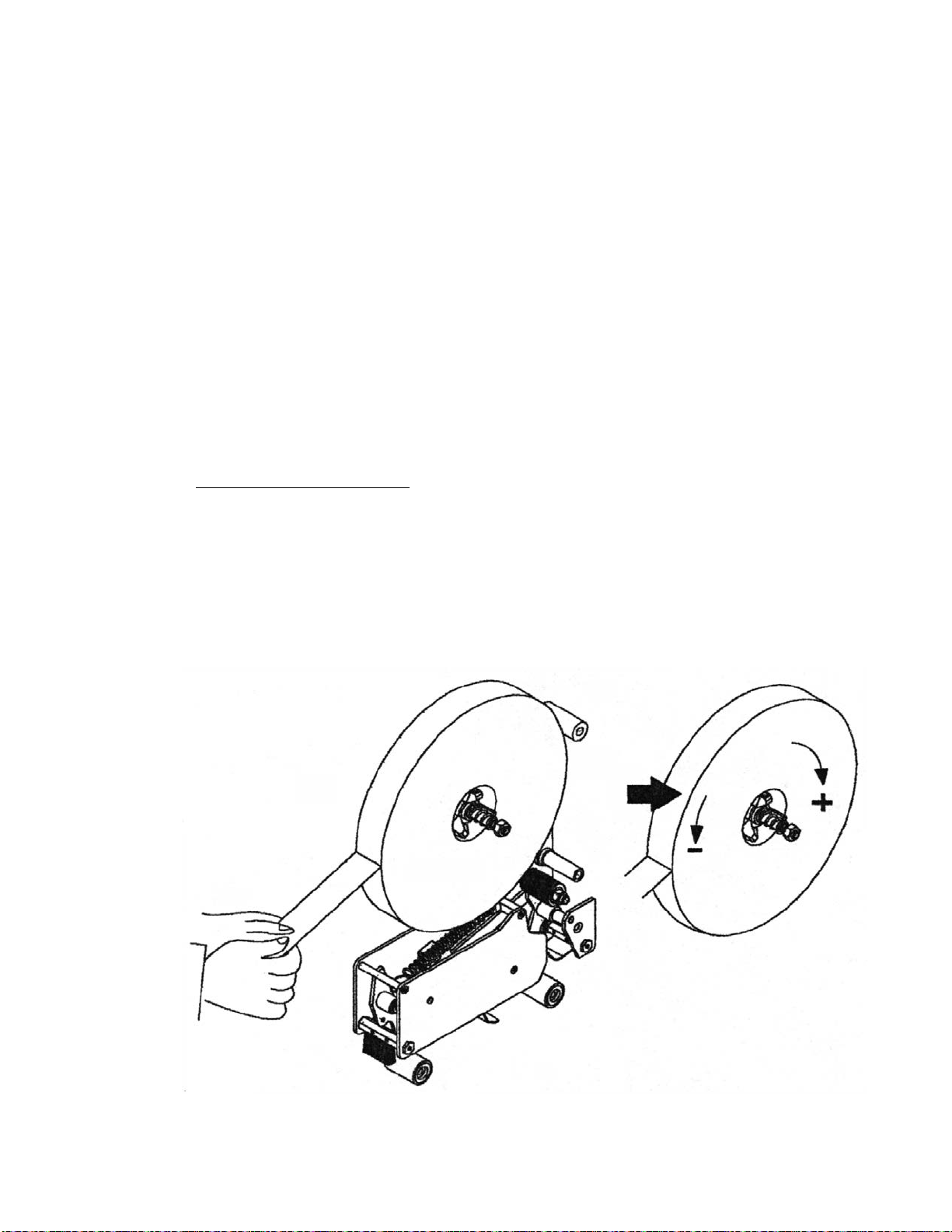
A. Centering the tape on rollers:
1. Make sure the tape is pushed fully against the backstop fingers (see figure
below).
2. Loosen the retaining nut several turns, but do not remove it altogether.
3. Standing on the tape loading side (side opposite from the controls), turn
the roll of tape (which will also turn the spindle) clockwise or counter-
clockwise until there is about ¼” gap between the support plate and the
backstop fingers (see figure below).
Backstop Fingers
Retaining Nut
Support Plate
¼” gap
4. Tighten the retaining nuts.
5. From the opposite side of the control panel, thread the tape through the
rollers according to the tape-threading diagram.
6. If the tape is not quite centered on the bass knurled roller as you pull the
tape through, loosen the retaining nut a few turns again. Turning the roll
of tape and the spindle clockwise will move the tape toward the controls
side; turning it counter-clockwise will move the tape toward the opposite
of the control panel.
7. When finished adjusting, tighten the retaining nut and check how the tape
moves through the rollers.
B. Checking the tape tension
The tape friction is preset to normal operation. Tape tension can be increased or
decreased as desired. Increase tension by turning the locking nut on the shaft
clockwise; decrease tension by turning counter-clockwise. Too much braking
force applied to the tape will cause poor tape application and may lead to tape
tabbing on the trailing tape leg.
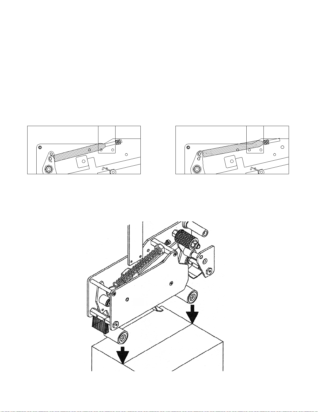
Spring Adjustment
The main spring adjusts the amount of tape wipe down on the front and rear tape legs
and their respective edges. For lightweight, unstable boxes, or weak corrugated,
decrease the spring tension to prevent the cases from stalling, tilting/jamming, or
deforming from high roller force. For the heavier boxes and strong corrugated, increase
the spring tension to ensure maximum tape wipe down. Use the inner screw position
on the rear roller arm for the low tension range and the outer screw position on the rear
roller arm for high tension. The threaded rod can be tightened or loosened for fine
tuning each of the tension ranges. See below.
Lowest possible tension setting shown above. Highest possible tension setting shown
above.
-Inner screw position on rear roller arm -Outer screw position on rear roller arm
-Loosened threaded rod position -Tightened threaded rod position
Table of contents
Other Highlight Packaging Equipment manuals


Popular Packaging Equipment manuals by other brands


Orion
Orion Sentry HP quick start guide

ITATOOLS
ITATOOLS ITA23 Operation manual & spare parts list

Jagenberg
Jagenberg Benhil 8345 Description and operating instructions

EXTENDGROUP
EXTENDGROUP EKH-455 Operation & maintenance manual

Ranpak
Ranpak Geami WrapRak HV Operator's manual

Sipromac
Sipromac 560A owner's manual