manuals.online logo
Brands
  1. Home
  2. •
  3. Brands
  4. •
  5. HIK VISION
  6. •
  7. IP Access Controllers
  8. •
  9. HIK VISION UD12126B-B User manual

HIK VISION UD12126B-B User manual

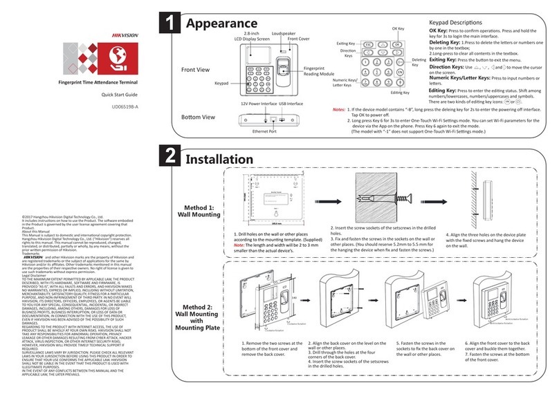
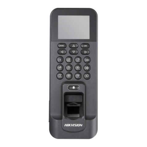
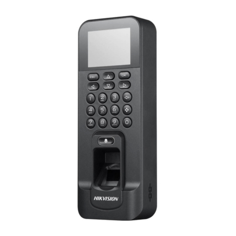
Fingerprint Access Control Terminal
Quick Start Guide
UD12126B-B
1
2
3Activation
Appearance
Installation
The default values of the terminal are as follows:
• The default IP address: 192.0.0.64
• The default port No.: 8000
• The default user name: admin
STRONG PASSWORD RECOMMENDED–
We highly recommend you create a strong password of your own choosing (using a minimum of 8 characters, including upper case leers, lower case leers,
numbers, and special characters) in order to increase the security of your product. And we recommend you reset your password regularly, especially in the high
security system, reseng the password monthly or weekly can beer protect your product.
Activating via Device
Power on and wire the network cable aer installaon.
You should acvate the device before the first login.
Aer powering on, the interface will be displayed as follows.
You can create the device password and confirm the password to acvate.
Exing Key
Direcon Keys
Numeric Keys/
Leer Keys
OK Key
Eding Key
Deleng
Key
ESC OK
12
ABC
3
DEF
4
GHI
6
MNO
7
PQRS
8
TUV
9
WXYZ
5
JKL
0
OK Key: Press to confirm operaons. Hold the key for 2 s to enter the login interface.
Deleting Key: Press the key to delete the entered leer or number.
Numeric Keys/Letter Keys: Enter numbers or leers.
Key 0 can also represent a space key except you are using the number input method.
Exiting Key: Press the key to exit the menu.
Direction Keys: Press , , and to move the cursor.
Editing Key: Press the key to enter the number 0. Hold the key to shi among
numbers/lowercases, numbers/uppercases and symbols.
Keypad Descriptions
©2019 Hangzhou Hikvision Digital Technology Co., Ltd.
It includes instrucons on how to use the Product. The soware embodied in the
Product is governed by the user license agreement covering that Product.
About this Manual
This Manual is subject to domesc and internaonal copyright protecon. Hangzhou
Hikvision Digital Technology Co., Ltd. (“Hikvision”) reserves all rights to this manual.
This manual cannot be reproduced, changed, translated, or distributed, parally or
wholly, by any means, without the prior wrien permission of Hikvision.
Trademarks
and other Hikvision marks are the property of Hikvision and are
registered trademarks or the subject of applicaons for the same by Hikvision and/or
its affiliates. Other trademarks menoned in this manual are the properes of their
respecve owners. No right of license is given to use such trademarks without express
permission.
Legal Disclaimer
TO THE MAXIMUM EXTENT PERMITTED BY APPLICABLE LAW, THE PRODUCT
DESCRIBED, WITH ITS HARDWARE, SOFTWARE AND FIRMWARE, IS PROVIDED “AS IS”,
WITH ALL FAULTS AND ERRORS, AND HIKVISION MAKES NO WARRANTIES, EXPRESS OR
IMPLIED, INCLUDING WITHOUT LIMITATION, MERCHANTABILITY, SATISFACTORY
QUALITY, FITNESS FOR A PARTICULAR PURPOSE, AND NON-INFRINGEMENT OF THIRD
PARTY. IN NO EVENT WILL HIKVISION, ITS DIRECTORS, OFFICERS, EMPLOYEES, OR
AGENTS BE LIABLE TO YOU FOR ANY SPECIAL, CONSEQUENTIAL, INCIDENTAL, OR
INDIRECT DAMAGES, INCLUDING, AMONG OTHERS, DAMAGES FOR LOSS OF BUSINESS
PROFITS, BUSINESS INTERRUPTION, OR LOSS OF DATA OR DOCUMENTATION, IN
CONNECTION WITH THE USE OF THIS PRODUCT, EVEN IF HIKVISION HAS BEEN
ADVISED OF THE POSSIBILITY OF SUCH DAMAGES.
REGARDING TO THE PRODUCT WITH INTERNET ACCESS, THE USE OF PRODUCT SHALL
BE WHOLLY AT YOUR OWN RISKS. HIKVISION SHALL NOT TAKE ANY RESPONSIBILITIES
FOR ABNORMAL OPERATION, PRIVACY LEAKAGE OR OTHER DAMAGES RESULTING
FROM CYBER ATTACK, HACKER ATTACK, VIRUS INSPECTION, OR OTHER INTERNET
SECURITY RISKS; HOWEVER, HIKVISION WILL PROVIDE TIMELY TECHNICAL SUPPORT IF
REQUIRED.
SURVEILLANCE LAWS VARY BY JURISDICTION. PLEASE CHECK ALL RELEVANT LAWS IN
YOUR JURISDICTION BEFORE USING THIS PRODUCT IN ORDER TO ENSURE THAT YOUR
USE CONFORMS THE APPLICABLE LAW. HIKVISION SHALL NOT BE LIABLE IN THE EVENT
THAT THIS PRODUCT IS USED WITH ILLEGITIMATE PURPOSES.
IN THE EVENT OF ANY CONFLICTS BETWEEN THIS MANUAL AND THE APPLICABLE LAW,
THE LATER PREVAILS.
Data Protecon
During the use of device, personal data will be collected, stored and processed. To
protect data, the development of Hikvision devices incorporates privacy by design
principles. For example, for device with facial recognion features, biometrics data is
stored in your device with encrypon method; for fingerprint device, only fingerprint
template will be saved, which is impossible to reconstruct a fingerprint image.
As data controller, you are advised to collect, store, process and transfer data in
accordance with the applicable data protecon laws and regulaons, including
without limitaon, conducng security controls to safeguard personal data, such as,
implemenng reasonable administrave and physical security controls, conduct
periodic reviews and assessments of the effecveness of your security controls.
Activating via SADP
1. Download SADP Soware: Get the SADP soware from the supplied disk or the official website. Install and run the soware.
2. Acvate Device: Check the inacve device from the device list. Create a password in the right side of the interface and confirm the password.
3. Edit Device IP Address: Check the device and manually edit the device IP address, Port No., Subnet Mask, Gateway, etc.
Activating via Client Software
1. Get the client soware from the supplied disk or the official website. Install and run the client soware.
2. Click Device Management to enter the Device Management interface.
3. Select an inacve device from the Online Device list. Click Acvate to pop up the Acvaon interface.
4. Create a password and confirm the new password. Click OK to acvate the device.
5. Click Modify Nenfo to set the device IP address, mask address, gateway address, and port No.
Display Screen
Keypad
Fingerprint Recognion Area
Card Swiping Area Power Interface
USB Interface
Network Interface
Wiring Terminal
140 mm
30 mm
155 mm
Steps:
1. Install the gang box on the wall.
Note: Make sure the gang box screw holes match the mounng plate’s. The gang box here
is for reference only. Select an appropriate gang box to install. The gang box is not supplied.
The recommanded gang box dimension is 78 × 78 mm or 100 × 62 mm.
2. Fix the mounng plate on the gang box with two supplied screws (SC-PM4X10-IMP).
3. Route the device cable through the cable hole of the mounng plate and insert the cables
in the gang box.
4. Align the terminal with the mounng plate, and secure the terminal on the mounng plate
with two supplied socket hexagon screws (SC-KM3X10_3-SUS).
1
2
3
Steps:
1. Sck a mounng template on the wall at a required height, and drill 4 holes according to the mounng
template on the wall.
Note: The suggested distance between the device lower edge and the ground is 1.3 m.
2. Insert 4 supplied expansion sleeves of the setscrews (4_KA4×22-SUS) in the drilled holes.
3. Fix and fasten the expansion bolts in the expansion sleeves respecvely.
Note: Reserve 5.2 mm to 5.5 mm of expansion bolts outside the wall for hanging the device.
4. Align four holes of the device rear panel with the fixed screws and hang the device on the wall.
Note: The addional force shall be equal to three mes the weight of the equipment but not less than
50 N. The equipment and its associated mounng means shall remain secure during the test. Aer the
test, the equipment, including any associated mounng plate, shall not be damaged.
With Gang Box Without Gang Box
4
Device Mounng
Plate
Gang Box
Doorbell
Buon
Doorbell Button: Press the doorbell buon and the doorbell rings.
120 mm
130.6 mm
25.15 mm
66.6 mm
53.2 mm
36.5 mm
83.65 mm
68.1 mm
ESC OK
12
ABC
3
DEF
4
GHI
6
MNO
7
PQRS
8
TUV
9
WXYZ
5
JKL
0
M4 Expansion Bolt
Expansion Sleeve
[Number]
OK Next. Input Method
Device Acvaon
Acvaon Password (8 to 16 Characters)
Notes:
1. The pictures here are for reference only. Some models do not support card swiping
funcon. For details, refer to the actual products.
2. If you enable the aendance status funcon, the OK key, the direcon key, and the
exing key can be the shortcut key of the aendance status.
4ConfigurationDevice Wiring
Attendance Configuration
2
User Management
1
Note: The external power supply and the access control terminal should use the same GND cable.
Manage User: In the New (New User) interface, enter the new user ID No., the user name, the card No. Register the fingerprint, set the password, select the department, set the user permission, select schedule template, set
the authencaon mode and set the duress card. Save the parameters to confirm adding.
Configure the shi via the device. You are able to schedule shi by department or by individual depending on the user property. The working flows are as follows:
Scheduling Shift by Department: Add User (See Step 1) - Edit Department - Configure Shi - Add Holiday - Configure Shi Schedule (by Department).
Edit Department:
Select a department to edit in the department list. Select “Edit”and edit the department name. Save the parameters.
Configure Shift
Normal Shi: In the Normal Shi page, configure the aendance rule, the normal shi aendance. Save the parameters to confirm seng.
Man-Hour Shi: In the Man-Hour Shi page, configure the man-hour shi parameters. Save the parameters to confirm seng.
Add Holiday
In the New (New Holiday) interface, enter the holiday No, the holiday name, the holiday start me and the holiday end me. Save the parameters.
Configure Shift Schedule
Schedule Shi by Department: Select a department to configure in the By Dept. (Schedule by Department) interface. Configure the shi, the start date, the end date and the holiday. Save the parameters.
Schedule Shi by Individual: Select New Individual Shi in the By Indiv. (Schedule by Individual) interface. Select a person to schedule in the New Individual Shi page. Configure the shi, the schedule start date and the
end date. Save the parameters.
External Device Wiring Overview
Attendance Report
Plug the USB flash drive in the device. Enter Aendance - Report, select a table type, create a device ID, select start date and end date. Press OK to export.
The device will automacally check the USB flahs drive memory. If there is no enough space for exporng, a prompt will be popped up. You can configure the record over threshold prompt and record delete
pafarmeters in the System page.
Record over Threshold Pop up Prompt (%): If the aendance record memory reaches the configured value, the system pops up a prompt to remind you. If configure the threshold to 99%, the system will pop
up a prompt to remind you to delete the aendance data when the capacity reaches the threshold.
The available value: 1 to 99.
Record Delete: When the funcon is enabled, the terminal will delete the first 3000 aendance records when the memory is full, in order to save the new aendance records. By default, the funcon is enabled. See
Secon 5.2 Aendance Record Delete Rule in User Manual of Fingerprint Time Aendance Terminal.
5
Scheduling Shift by Individual: Add User (See Step 1) - Configure Shi - Add Holiday - Configure Shi Schedule (by Individual).
User Management and Aendance Configuraon are two main parts of the Access Control Terminal.
Regulatory Information This product and - if applicable - the supplied accessories too are
marked with "CE" and comply therefore with the applicable
harmonized European standards listed under the RE Direcve
2014/53/EU, the EMC Direcve 2014/30/EU, the RoHS Direcve
2011/65/EU.
2012/19/EU (WEEE direcve): Products marked with this symbol
cannot be disposed of as unsorted municipal waste in the European
Union. For proper recycling, return this product to your local
supplier upon the purchase of equivalent new equipment, or
dispose of it at designated collecon points. For more informaon
see: www.recyclethis.info
2006/66/EC (baery direcve): This product contains a baery that
cannot be disposed of as unsorted municipal waste in the European
Union. See the product documentaon for specific baery
informaon. The baery is marked with this symbol, which may
include leering to indicate cadmium (Cd), lead (Pb), or mercury (Hg).
For proper recycling, return the baery to your supplier or to a
designated collecon point. For more informaon see:
www.recyclethis.info
Industry Canada ICES-003 Compliance
This device meets the CAN ICES-3 (B)/NMB-3(B) standards requirements.
This device complies with Industry Canada licence-exempt RSS standard(s). Operaon is subject to the following two
condions:
(1) this device may not cause interference, and
(2) this device must accept any interference, including interference that may cause undesired operaon of the device.
Le présent appareil est conforme aux CNR d'Industrie Canada applicables aux appareils radioexempts de licence.
L'exploitaon est autorisée aux deux condions suivantes :
(1) l'appareil ne doit pas produire de brouillage, et
(2) l'ulisateur de l'appareil doit accepter tout brouillage radioélectrique subi, même si le brouillage est suscepble
d'en compromere le fonconnement.
Under Industry Canada regulaons, this radio transmier may only operate using an antenna of a type and maximum
(or lesser) gain approved for the transmier by Industry Canada. To reduce potenal radio interference to other users,
the antenna type and its gain should be so chosen that the equivalent isotropically radiated power (e.i.r.p.) is not more
than that necessary for successful communicaon.
Conformément à la réglementaon d'Industrie Canada, le présent émeeur radio peut
fonconner avec une antenne d'un type et d'un gain maximal (ou inférieur) approuvé pour l'émeeur par Industrie
Canada. Dans le but de réduire les risques de brouillage radioélectrique à l'intenon des autres ulisateurs, il faut
choisir le type d'antenne et son gain de sorte que la puissance isotrope rayonnée équivalente (p.i.r.e.) ne dépasse pas
l'intensité nécessaire à l'établissement d'une communicaon sasfaisante.
This equipment should be installed and operated with a minimum distance 20cm between the radiator and your body.
Cet équipement doit être installé et ulisé à une distance minimale de 20 cm entre le radiateur et votre corps.
FCC Conditions
This device complies with part 15 of the FCC Rules. Operaon is subject to the following two
condions:
1. This device may not cause harmful interference.
2. This device must accept any interference received, including interference that may cause
undesired operaon.
EU Conformity Statement
FCC Information
Please take aenon that changes or modificaon not expressly approved by the party responsible for compliance could
void the user’s authority to operate the equipment.
FCC compliance: This equipment has been tested and found to comply with the limits for a Class B digital device,
pursuant to part 15 of the FCC Rules. These limits are designed to provide reasonable protecon against harmful
interference in a residenal installaon. This equipment generates, uses and can radiate radio frequency energy and, if
not installed and used in accordance with the instrucons, may cause harmful interference to radio communicaons.
However, there is no guarantee that interference will not occur in a parcular installaon. If this equipment does cause
harmful interference to radio or television recepon, which can be determined by turning the equipment off and on, the
user is encouraged to try to correct the interference by one or more of the following measures:
—Reorient or relocate the receiving antenna.
—Increase the separaon between the equipment and receiver.
—Connect the equipment into an outlet on a circuit different from that to which the receiver is connected.
—Consult the dealer or an experienced radio/TV technician for help.
This equipment should be installed and operated with a minimum distance 20cm between the radiator and your body.
Use only power supplies listed in the user instrucons:
Model Manufacturer Standard
DSA-12PFT-12FUK 120100
DSA-12PFT-12FAU 120100
DSA-12PFT-12FIN 120100
DSA-12PFT-12FUS 120100
DSA-12PFT-12 FBZ 120100
Dee Van Enterprise Co., Ltd. BS
Dee Van Enterprise Co., Ltd.
AS
NBR
IEC
IS
Door Magnec Contact
Gourp B
Gourp C
B1
B2
B3
B4
B5
B6
C1
C2
Black
Red
Yellow
View License:
You can view the device License via the website: hp://opensource.hikvision.com/Home/List?id=46
Scan the QR code to get the
user manual for detailed
informaon.
Note that mobile data
charges may apply if Wi-Fi is
unavailable.
Other Settings
3
Manage Data: Enter System - Data page, and select Delete Event Only, Delete Aendance Data Only, Delete User Only, or Clear Permisison to manage the system data.
Factory Defualts: Enter System - Reset page, and select Factory Defaults. All device parameters will restore to the factory sengs.
Default Settings: Enter System - Reset page, and select Default Sengs. All parameters, excluding the communicaon parameters, and the remote user management paramters, will restore to factory sengs.
Upgrage Device: Plug an USB flash drive to the device USB falsh drive interface. Tap System - Upgrade and tap OK to upgrade the device. The device will reboot automacally aer upgrading is completed.
Notes:
1. The upgrading file should be in the root directoy in the USB flash drive.
2. The upgrading file name should be digicap.dav.
3. Do not power off when device is upgrading.
External Device Wiring Terminal Descripon
Line
Group
No. Funcon Color
Terminal
Name
Descripon
Line
Group A
A1
Power Input
Red
+12V
12V DC Power Supply
A2
Black
GND
GND
Line
Group B
B1
Lock
White/Purple
NC
Lock Wiring
B2
White/Yellow
COM
B3
White/Red
NO
B4
Yellow/Green
SENSOR
Door Contact Signal
Input
B5
Black
GND
GND
B6
Yellow/Grey
BUTTON
Exit Door Wiring
Line
Group C
C1
Door Bell
Red
BELL+
Door Bell Wiring
C2
Yellow
BELL-
CAUTION
RISK OF EXPLOSION IF BATTERY IS
REPLACED BY AN INCORRECT TYPE.
DISPOSE OF USED BATTERIES
ACCORDING TO THE INSTRUCTIONS.
Hik-Connect: You can operate the device via the Hik-Connect mobile client.
Other HIK VISION IP Access Controllers manuals

HIK VISION DS-TME401-TPC User manual

HIK VISION

HIK VISION DS-TME401-TPC User manual

HIK VISION DS-K2801 User manual

HIK VISION

HIK VISION DS-K2801 User manual

HIK VISION DS-K1A802 Series User manual

HIK VISION

HIK VISION DS-K1A802 Series User manual

HIK VISION 26 series User manual

HIK VISION

HIK VISION 26 series User manual

HIK VISION DS-K281 Series User manual

HIK VISION

HIK VISION DS-K281 Series User manual

HIK VISION DS-K2601 Operating and maintenance instructions

HIK VISION

HIK VISION DS-K2601 Operating and maintenance instructions

HIK VISION DS-K5603-Z User manual

HIK VISION

HIK VISION DS-K5603-Z User manual

HIK VISION DS-K1F600U-D6E Series User manual

HIK VISION

HIK VISION DS-K1F600U-D6E Series User manual

HIK VISION K1T604 Quick guide

HIK VISION

HIK VISION K1T604 Quick guide

HIK VISION DS-K1T802 User manual

HIK VISION

HIK VISION DS-K1T802 User manual

HIK VISION DS-K1100 Series User manual

HIK VISION

HIK VISION DS-K1100 Series User manual

HIK VISION DS-K1801 Series User manual

HIK VISION

HIK VISION DS-K1801 Series User manual

HIK VISION DS-K281X Series User manual

HIK VISION

HIK VISION DS-K281X Series User manual

HIK VISION DS-K1T501 User manual

HIK VISION

HIK VISION DS-K1T501 User manual

HIK VISION DS-K2802 User manual

HIK VISION

HIK VISION DS-K2802 User manual

HIK VISION DS-K1T105E-C User manual

HIK VISION

HIK VISION DS-K1T105E-C User manual

HIK VISION DS-K1T501SF User manual

HIK VISION

HIK VISION DS-K1T501SF User manual

HIK VISION DS-K1T673-T Series User manual

HIK VISION

HIK VISION DS-K1T673-T Series User manual

HIK VISION DS-PTA-WL-868 User manual

HIK VISION

HIK VISION DS-PTA-WL-868 User manual

HIK VISION DS-K1T804A Series User manual

HIK VISION

HIK VISION DS-K1T804A Series User manual

HIK VISION DS-K2600 Series User manual

HIK VISION

HIK VISION DS-K2600 Series User manual

HIK VISION DS-K2600 Series User manual

HIK VISION

HIK VISION DS-K2600 Series User manual

HIK VISION DS-K2804 User manual

HIK VISION

HIK VISION DS-K2804 User manual

HIK VISION MinMoe DS-K1T671TM-3XF User manual

HIK VISION

HIK VISION MinMoe DS-K1T671TM-3XF User manual

Popular IP Access Controllers manuals by other brands

Techsphere VP-II M installation guide

Techsphere

Techsphere VP-II M installation guide

Sanela SLZA 40GV Mounting instructions

Sanela

Sanela SLZA 40GV Mounting instructions

xpr B100PROX-EH-SA v2 Installer manual

xpr

xpr B100PROX-EH-SA v2 Installer manual

fadini ZERO.SAPE manual

fadini

fadini ZERO.SAPE manual

FingerTec AC100C quick start guide

FingerTec

FingerTec AC100C quick start guide

ZKTeco MultiBio 700 installation guide

ZKTeco

ZKTeco MultiBio 700 installation guide

Fermax AC-MAX KIT 2 DOORS Installer manual

Fermax

Fermax AC-MAX KIT 2 DOORS Installer manual

LEGRAND Raritan SmartLock DX2-DH2C2 Quick setup guide

LEGRAND

LEGRAND Raritan SmartLock DX2-DH2C2 Quick setup guide

Sebury F007-EM user manual

Sebury

Sebury F007-EM user manual

Third Millennium OC1 manual

Third Millennium

Third Millennium OC1 manual

ZKaccess InBio Pro quick start guide

ZKaccess

ZKaccess InBio Pro quick start guide

Anviz T50 user manual

Anviz

Anviz T50 user manual

Roger MCT86M-IO-CH-HR installation manual

Roger

Roger MCT86M-IO-CH-HR installation manual

Assa Abloy Aperio Quick installation guide

Assa Abloy

Assa Abloy Aperio Quick installation guide

eSSL F18 user manual

eSSL

eSSL F18 user manual

Dahua Technology DHI-ASC3202B quick start guide

Dahua Technology

Dahua Technology DHI-ASC3202B quick start guide

Visonic Networks TAG-IN-A-BAG Installation and programming guide

Visonic Networks

Visonic Networks TAG-IN-A-BAG Installation and programming guide

MPicoSys PicoLabel 2.7" Demo Kit user guide

MPicoSys

MPicoSys PicoLabel 2.7" Demo Kit user guide

manuals.online logo
manuals.online logoBrands
  • About & Mission
  • Contact us
  • Privacy Policy
  • Terms and Conditions

Copyright 2025 Manuals.Online. All Rights Reserved.