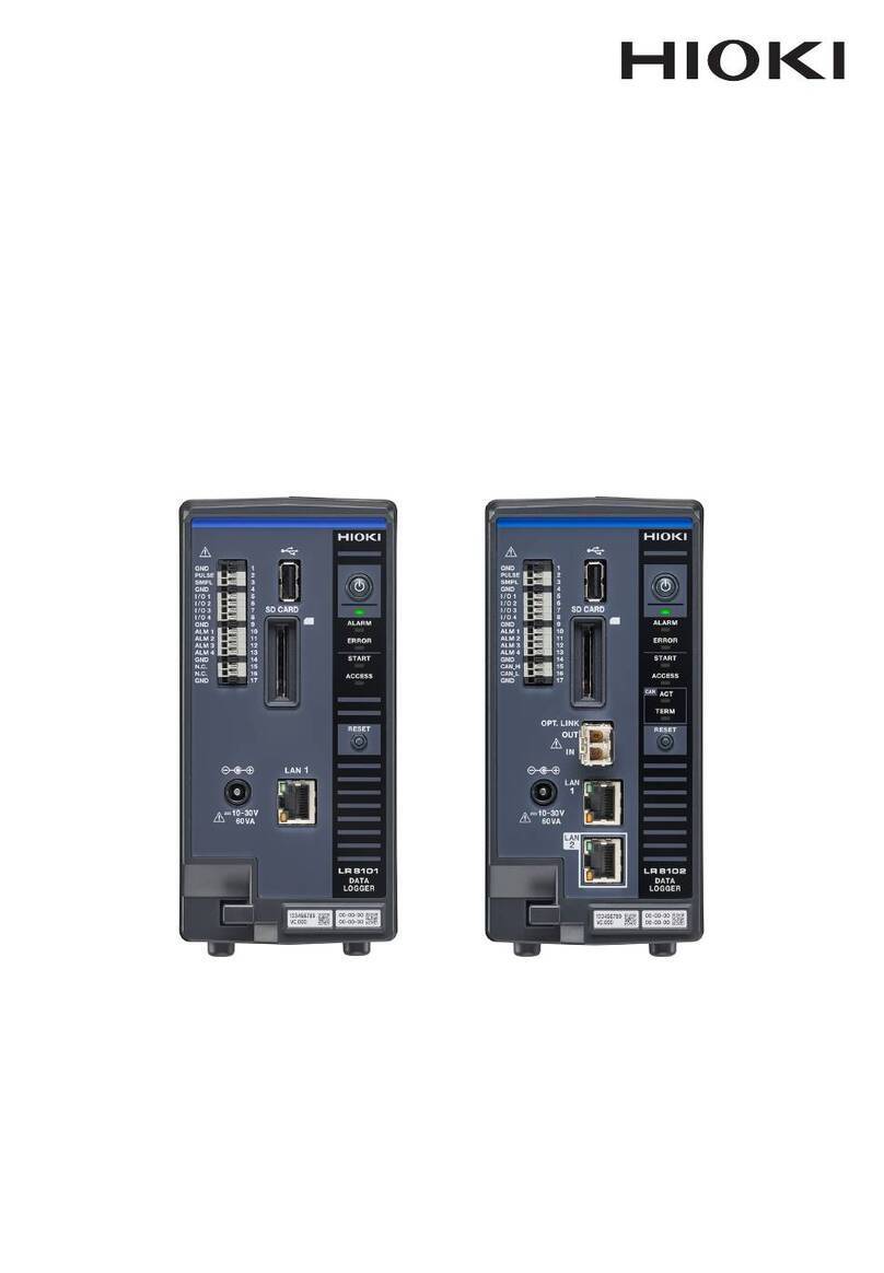
Hioki LR5031 User manual

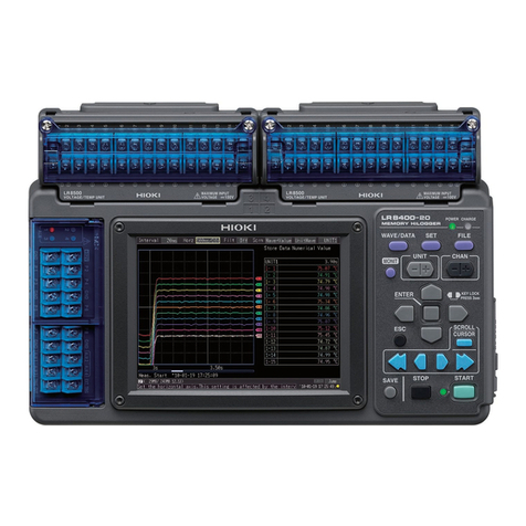
LR5031 Instruction Manual
INSTRUMENTATION LOGGER
EN
Dec. 2018 Revised edition 5
LR5031B980-05 18-12H
Be sure to read this manual
before using the instrument Safety Information p.6
When using the instrument
for the rst time Troubleshooting
Part Names/Functions
and Display Indicators p.14 Maintenance and Service p.91
Troubleshooting p.92
Settings List p.29 Error Display p.94
www. .com information@itm.com1.800.561.8187

Contents
i
Contents
Introduction ..............................................................................1
Verifying Package Contents....................................................4
Safety Information....................................................................6
Operating Precautions.............................................................8
Measurement Preparation to Data Analysis ........................10
Chapter 1
Overview__________________________________ 13
1.1 Product Overview and Features .............................13
1.2 Part Names/Functions and Display Indicators .....14
1.3 Display Organization ...............................................16
Chapter 2
Measurement Preparations___________________ 19
2.1 Installing (or Replacing) the Battery ......................19
2.2 Connecting the Connection Cable .........................22
2.3 Installing the PC Application Program ..................23
Chapter 3
Settings___________________________________ 29
3.1 Settings List .............................................................29
3.2 Making Settings on the Logger ..............................31
3.3 Making Settings from the LR5000 Utility Program 35
Chapter 4
Measurement and Analysis___________________ 43
4.1 Pre-Measurement Inspection .................................43
4.2 Installing the Logger ...............................................44
4.3 Starting and Stopping Recording ..........................46
4.4 Confirming Currently Measured Values and Data
Recording .................................................................49
4.5 Automatically Importing (Saving) Recorded Data
to a Computer, and Graph Display ........................49
1
2
3
4
LR5031B980-05
www. .com information@itm.com1.800.561.8187

Contents
ii
4.6 Manually Importing (Saving) Recorded Data to a
Computer, and Graph Display ............................... 59
4.7 Displaying a Graph of Saved Recording Data ..... 62
4.8 Printing Recorded Data .......................................... 64
Chapter 5
Processing Recorded Data ___________________65
5.1 Scaling ..................................................................... 67
5.2 Calculating Electric Power ..................................... 68
5.3 Calculating Energy Cost ........................................ 69
5.4 Calculating Operating Rate .................................... 70
5.5 Integration ............................................................... 71
5.6 Calculating Dew-Point Temperature ..................... 72
5.7 Two-Data-Item Arithmetic Calculations ................ 73
5.8 Converting Over-Threshold Data Values .............. 74
Chapter 6
Organizing Data ____________________________75
6.1 Copying and Moving Data ...................................... 76
6.2 Deleting Data ........................................................... 77
6.3 Combining Data ...................................................... 78
6.4 Extracting Data ....................................................... 79
Chapter 7
Options Settings (LR5000 Utility Program) ______81
7.1 Changing the Saving Method for Imported Data . 82
7.2 Changing the Connection Monitoring Method,
and Logger Settings Displays ............................... 83
Chapter 8
Specifications______________________________85
8.1 Measurement Specifications ................................. 85
8.2 Functional Specifications ...................................... 86
8.3 Miscellaneous ......................................................... 87
8.4 LR5091 Communication Adapter Specifications . 88
www. .com information@itm.com1.800.561.8187

Contents
iii
Chapter 9
Maintenance and Service ____________________ 91
9.1 Cleaning ...................................................................91
9.2 Disposing of the Logger .........................................91
9.3 Troubleshooting ......................................................92
9.4 Error Display ............................................................94
Appendix_________________________________ A 1
Appendix 1 About Recording Modes..............................A 1
Appendix 2 Recording Intervals and Recording Times A 2
Appendix 3 Battery Life Approximation.........................A 2
Index _________________________________Index 1
4
5
6
7
8
9
Appendix
Index
www. .com information@itm.com1.800.561.8187
Introduction
1
Thank you for purchasing the HIOKI "Model LR5031 Instrumentation Logger." To
obtain maximum performance from the instrument, please read this manual first,
and keep it handy for future reference.
• Microsoft and Windows are either registered trademarks or trademarks of Microsoft
Corporation in the United States and other countries.
• Microsoft and Windows, Windows Vista, Microsoft Excel are either registered trade-
marks or trademarks of Microsoft Corporation in the United States and other countries.
The screen of this instrument displays characters in the following man-
ner.
Introduction
Trademarks
Notation
Indicates a prohibited action.
(p. ) Indicates the location of reference information.
Indicates quick references for operation and remedies for
troubleshooting.
*Indicates that descriptive information is provided below.
[ ] Menus, commands, dialogs, buttons in a dialog, and other
names on the screen and the keys are indicated in brack-
ets.
SET
(Bold
characters)
Bold characters within the text indicate operating button
labels.
Windows Unless otherwise specified, "Windows" represents Win-
dows XP, Windows Vista, or Windows 7.
Dialog Dialog box represents a Windows dialog box.
www. .com information@itm.com1.800.561.8187
Introduction
2
We define measurement tolerances in terms of rdg. (reading) and dgt.
(digit) values, with the following meanings:
Accuracy
rdg.
(reading or displayed value) The value currently being measured and indicated
on the measuring instrument.
dgt.
(resolution)
The smallest displayable unit on a digital measur-
ing instrument, i.e., the input value that causes the
digital display to show a "1" as the least-significant
digit.
www. .com information@itm.com1.800.561.8187

Introduction
3
Mouse Operation
Click Press and quickly release the left button of the mouse.
Right-click Press and quickly release the right button of the mouse.
Double click Quickly click the left button of the mouse twice.
Drag While holding down the left button of the mouse, move the
mouse and then release the left button to deposit the cho-
sen item in the desired position.
Activate Click on a window on the screen to activate that window.
www. .com information@itm.com1.800.561.8187
Verifying Package Contents
4
When you receive the instrument, inspect it carefully to ensure that no damage
occurred during shipping. In particular, check the accessories, panel switches, and
connectors. If damage is evident, or if it fails to operate according to the specifica-
tions, contact your dealer or Hioki representative.
Quantities in parentheses ( ).
Verifying Package Contents
LR5031 (1)
LR6 alkaline battery (1)
(Pre-installed in the log-
ger.)
Accessories
See: Other specified options:"Options" (p.5)
LR9801 Connection Cable
(Cable length: Approx. 1 m) (1)
Instruction Manual (1)Operation Manual (1)
Stand (1)
www. .com information@itm.com1.800.561.8187
Verifying Package Contents
5
The following logger options are available separately. Even if purchased previously,
you may want to confirm that you have them at hand.
Use the original packing materials when transporting the instrument, if possible.
Pack the instrument so that it will not sustain damage during shipping, and include a
description of existing damage. We do not take any responsibility for damage incurred
during shipping.
Options
LR9801 Connection Cable
(Cable length: Approx. 1 m)
LR5091 Communication Adapter(1)
(Includes LR5000 Utility Program*CD [PC appli-
cation software] and USB Cable)
*: The latest version can be download-
ed from our web site.
See: LR5091 specification: (p.88)
LR9901 Wall-Mounted Holder
Z5004 Magnetic StrapLR5092-20 Data Collector
(Includes LR5000 Utility Program*CD [PC ap-
plication software], LR6 alkaline battery x2, In-
struction manual, Operation manual, and USB
Cable)
See: Method of mounting: (p.45)
Transporting Precautions
www. .com information@itm.com1.800.561.8187
Safety Information
6
This manual contains information and warnings essential for safe operation of the
instrument and for maintaining it in safe operating condition. Before using it, be
sure to carefully read the following safety precautions.
Markings on the logger have the following meanings.
Safety Information
This instrument is designed to comply with IEC 61010 Safety Stan-
dards, and has been thoroughly tested for safety prior to ship-
ment. However, mishandling during use could result i n injury or
death, as well a s damage to the instrument. However, using the
instrument in a way not described in this manual may negate the
provided safety features.
Be certain that you understand the instructions and precautions in
the manual before use. We disclaim any responsibility for acci-
dents or injuries not resulting directly from instrument defects.
Safety Symbols
In the manual, the symbol indicates particularly important infor-
mation that the user should read before using the instrument.
The symbol printed on the instrument indicates that the user
should refer to a corresponding topic in the manual (marked with the
symbol) before using the relevant function.
Indicates DC (Direct Current).
Symbols for Various Standards
Indicates that the product conforms to regulations set out by the EU
Directive.
This symbol indicates that the product conforms to safety regu-
lations set out by the EC Directive.
www. .com information@itm.com1.800.561.8187

Safety Information
7
The following symbols in this manual indicate the relative importance of cautions and
warnings.
Danger Levels
Indicates that incorrect operation presents an extreme hazard
that could result in serious injury or death to the user.
Indicates that incorrect operation presents a significant hazard
that could result in serious injury or death to the user.
Indicates that incorrect operation presents a possibility of
injury to the user or damage to the instrument.
Indicates advisory items related to performance or correct
operation of the instrument.
www. .com information@itm.com1.800.561.8187
Operating Precautions
8
Follow these precautions to ensure safe operation and to obtain the full ben-
efits of the various functions.
Operating temperature and humidity: -20C to70C (-4.0F to 158.0F), 80%RH or
less (non-condensating)
Storage temperature and humidity : -20C to70C (-4.0F to 158.0F) 80%RH or
less (non-condensating)
*IP54 :This indicates the degree of protection provided by the enclosure of the
device against use in hazardous locations, entry of solid foreign objects,
and the ingress of water.
5 : Protected against access to hazardous parts with wire measuring 1.0
mm in diameter. Dust-proof type (The penetrationof dustcannot bepre-
vented completely, but quantities of dust that may hinder the stated op-
eration of equipment or safety cannot penetrate the enclosure.
4 : The equipment inside the enclosure is protected against the harmful ef-
fects of spraying water.
Operating Precautions
Installation Precautions
Avoid the following locations that could cause an accident or damage to the instru-
ment.
Exposed to direct
sunlight
Exposed to high tem-
perature
In the presence of
corrosive or explosive
gases
Exposed to liquids
Exposed to high
humidity or condensa-
tion
Exposed to strong
electromagnetic
fields
Near electromagnetic
radiators
Subject to vibration
Near induction heat-
ing systems
(e.g., high-frequency
induction heating sys-
tems and IH cooking
utensils)
• The protection rating for the enclosure of this device (based on
EN60529) is *IP54.
• Although this instrument is designed to resist the ingress of dust and
water, it is not entirely water- or dust-proof, so to avoid shock or dam-
age, do not use it in a wet or dusty environment.
www. .com information@itm.com1.800.561.8187

Operating Precautions
9
Before using the instrument the first time, verify that it operates normally to ensure
that the no damage occurred during storage or shipping. If you find any damage, con-
tact your dealer or Hioki representative.
Avoiding Instrument Damage
To avoid damage to the instrument, protect it from physical shock when
transporting and handling. Be especially careful to avoid physical shock
from dropping.
CD Handling
• Always hold the disc by the edges, so as not to make fingerprints on
the disc or scratch the printing. Never touch the recorded side of the
disc. Do not place the disc directly on anything hard.
• Do not wet the disc with volatile alcohol or water, as there is a possibil-
ity of the label printing disappearing.
• To write on the disc label surface, use a spirit-based felt pen. Do not
use a ball-point pen or hard-tipped pen, because there is a danger of
scratching the surface and corrupting the data. Do not use adhesive
labels.
• Do not expose the disc directly to the sun's rays, or keep it in condi-
tions of high temperature or humidity, as there is a danger of warping,
with consequent loss of data.
• To remove dirt, dust, or fingerprints from the disc, wipe with a dry
cloth, or use a CD cleaner. Always wipe from the inside to the outside,
and do no wipe with circular movements. Never use abrasives or sol-
vent cleaners.
• Hioki shall not be held liable for any problems with a computer system
that arises from the use of this CD, or for any problem related to the
purchase of a Hioki product.
Preliminary Checks
Before using the instrument, make sure that the insulation on the
connection cables is undamaged and that no bare conductors are
improperly exposed. Using the instrument in such conditions
could cause an electric shock, so contact your dealer or Hioki rep-
resentative for replacements.
www. .com information@itm.com1.800.561.8187
Measurement Preparation to Data Analysis
10
The steps from measurement preparation to data analysis are illustrated with a typ-
ical measurement example.
Example Case: Record a factory flow sensor output signal (4-20 mA) at one-minute
intervals for one month, and store the data on a computer.
Quantities in parentheses ( ).
Measurement Preparation to Data Analysis
Required Items:
LR5031 (1) LR6 alkaline battery (1) LR9801 Connection Cable (1)
LR5091 Communication Adapter(1)
(LR5000 Utility Program* CD [PC applica-
tion software] and USB Cable)
Computer (1)
Procedure:
1Install the battery in the logger.
See: "2.1" (p.19)
2Connect the LR9801 Connection Cable to
the logger.
See: "2.2" (p.22)
1
2
www. .com information@itm.com1.800.561.8187
Measurement Preparation to Data Analysis
11
3Install the LR5000 Utility Program on the
computer.
See: "2.3" (p.23)
4Select the recording interval for the logger
(in this case, 1 minutes).
See: "Recording Interval Setting" (p.31)
(The setting can be made also from the
LR5000 Utility Program.) (p.38)
5Set the logger to the correct date and time
(in this case, 15 May 2010, 13:00).
See: "Real-Time Clock Setting" (p.32)
(With the LR5000 Utility Program, the log-
ger can be set to the computer time.)
(p.41)
6Set the stop method to [OFF].
(This setting provides one-time measurement:
recording stops when memory becomes full.)
See: "Stop Method Setting (for when
memory becomes full)" (p.33)
(The setting can be made also from the
LR5000 Utility Program.) (p.38)
5
4
3
6
www. .com information@itm.com1.800.561.8187
Measurement Preparation to Data Analysis
12
7Set the recording mode to [OFF].
(This setting provides instantaneous mea-
surement.)
See: "Recording Mode Setting" (p.34)
(The setting can be made also from the
LR5000 Utility Program.) (p.38)
8Set the power save setting to [ON].
(The on (enabled) setting is recommended
for long-term recording.)
See: "Power Save Setting" (p.34)
(The setting can be made also from the
LR5000 Utility Program.) (p.37)
9Pre-measurement inspection (p.43)
10 Install the logger at the measurement
site in the factory.
See: "4.2" (p.44)
(It can be wall-mounted.)
11 Hold REC/STOP on the logger for two
seconds to start recording.
(Confirm that the recording data count is
incrementing and that recording is actually
occurring.)
See: "4.3" (p.46)
12 Switch the logger display by pressing the
(+) and (-) buttons to check maximum
and minimum recorded values.
(Confirm that recording is actually occurring.)
See: "4.4" (p.49)
13 After a month, hold REC/STOP on the log-
ger again for two seconds to stop recording.
See: "4.3" (p.46)
14 Retrieve the logger from the measure-
ment site.
15 Import recorded data from the logger to
a connected computer. For analysis, dis-
play the data in a graph.
See: "4.5" (p.49)
(The data is automatically saved when
imported to the computer. By default, it is
also automatically displayed in a graph.)
16 Print recorded data as needed.
See: "4.8" (p.64)
8
11
7
15
12
www. .com information@itm.com1.800.561.8187

1.1 Product Overview and Features
13
3
1
Chapter 1 Overview
This instrument is a compact portable data logger for measuring, displaying, and
recording DC current.
Overview Chapter 1
1.1 Product Overview and Features
Browse and manage data with
LR5000 Utility Program on a PC.
The LR5000 Utility Program PC applica-
tion is very easy to install.
After installation, data management and
browsing is easy with auto-start, data dis-
play and saving.
• Data can be imported while recording.
• Records up to 60,000 measurements
• Data is preserved independently
of battery state
• Recording continues (for approx.
30 s) during battery replacement
Splash-proof
ingress protec-
tion (IP54)
Advanced functions included
• Record statistical values (p.34), (p.38)
• Scaling (p.39), (p.67)
• Alarm display (p.40)
Large display shows measured
current value and recorded
data count
Measures DC current (one channel).
Measurement
Sites
Analysis Site
Measures the output of vari-
ous sensors in the factory
Suitable for ESCO, ISO, and simi-
lar measurement applications.
www. .com information@itm.com1.800.561.8187
1.2 Part Names/Functions and Display Indicators
14
1.2 Part Names/Functions and Display Indicators
IR Port
(p.49)
Communicates
with the LR5091
Communication
Adapter or
LR5092-20 Data
Collector
Front
LCD (p.15)
The display blanks after 30 seconds of oper-
ator inactivity (auto power save).The display
reappears by pressing a button.
Whenthedisplay isvisible, itrefreshesabout
once per second. Battery
Cover (p.19)
SET button
Displays settings.
Back
Operation Buttons
(-) button, (+) button
Changes Measurement display contents.
Changes setting values on the Settings display.
REC/STOP button
Hold for two seconds to start/stop recording.
From a setting display, switches to measurement
display.
Connection cable Jack
(p.22)
Connect a connection cable.
Operation buttons
LR5091 Communication Adapter
IR Port (p.49)
Communicates with the logger.
USB Port (p.35)
Connect a USB cable here to communicate with a
computer. (Mini-B receptacle)
Stand/Strap Attachment Hole (p.44)
Attach the logger to a wall or other surface by
hanging it on a screw. (Supported screw head di-
mensions: up to approx. 6.8 mm in diameter and
approx. 2.5 mm in thickness)
www. .com information@itm.com1.800.561.8187
1.2 Part Names/Functions and Display Indicators
15
3
1
Chapter 1 Overview
The display indicators provide the following information.
Display Indicators
REC Indicator
Indicates recording in progress. (Blinks when waiting to record.)
AL indicator
When the alarm* function is enabled, this indicates when a mea-
sured value is outside of the specified (upper/lower value*) range.
ENDLESS indicator
Indicates the Stop Method Setting display.
Also appears on the Measurement display to indicate
endless recording (p.33) is enabled.
Not used by the logger.
Battery Status Indicator
Indicates the battery charge status. (p.20)
Units
Indicates the unit of
measurement on
each channel.
(not displayed when
scaling* is enabled)
Measurement
Channel
MAX indicator
Indicates that the
value displayed
at the right is the
maximum.
MIN indicator
Indicates that the
value displayed at
the right is the mini-
mum.
DATA indicator
Indicates that the value displayed
at the right is the data count.
* Setting is available from the LR5000 Utility Program or via the LR5092-20 Data Col-
lector.
See: "3.3 Making Settings from the LR5000 Utility Program" (p.35), LR5092-20 Data
Collector Instruction Manual
TIME indicator
Indicates the Date-Time Setting display.
INTVL indicator
Indicates the Recording Interval Setting display.
STAT indicator
Indicates the Recording Mode Setting display.
Also appears on the Measurement display to
indicate statistic recording (p.34) is enabled.
www. .com information@itm.com1.800.561.8187

1.3 Display Organization
16
The logger has two general display types: Measurement and Settings.
The (+) and (-) buttons switch the display type.
1.3 Display Organization
Measuring display
• For instantaneous recording, the maximum and minimum values are
obtained from all the data measured at each recording interval.
• For statistical recording, the maximum and minimum values are
obtained from all the data measured every second.
• The maximum and minimum values are not displayed when the
recorded data count is 0.
Measured value
Recorded data
count
Maximum value
Minimum value
www. .com information@itm.com1.800.561.8187
This manual suits for next models
1
Table of contents
Other Hioki Data Logger manuals

Hioki
Hioki 8423 User manual

Hioki
Hioki LR8431-20 User manual

Hioki
Hioki LR8101 User guide

Hioki
Hioki LR8512 User manual

Hioki
Hioki LR8410-20 User manual

Hioki
Hioki HiLogger 3145-20 User manual

Hioki
Hioki LR8450 User manual

Hioki
Hioki LR8450 User manual

Hioki
Hioki LR5051 User manual

Hioki
Hioki lr5001 User manual

Hioki
Hioki Hioki Instruction manual

Hioki
Hioki LR8432-20 User manual

Hioki
Hioki lr5001 User manual

Hioki
Hioki LR8520 User manual

Hioki
Hioki LR8431-20 User manual

Hioki
Hioki 3639-20 User manual

Hioki
Hioki 3631-20 User manual

Hioki
Hioki LR8400-20 User manual

Hioki
Hioki 8861 Instruction manual

Hioki
Hioki LR5092-20 User manual