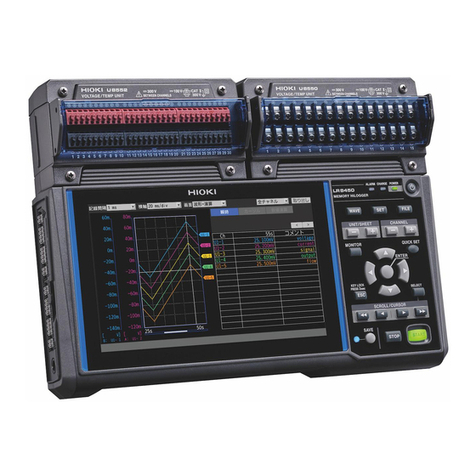
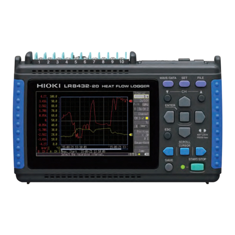
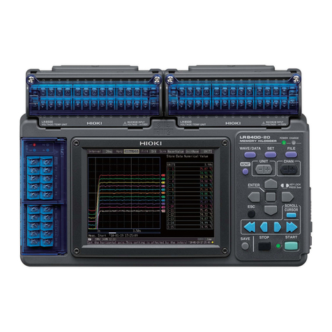
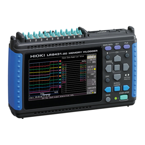
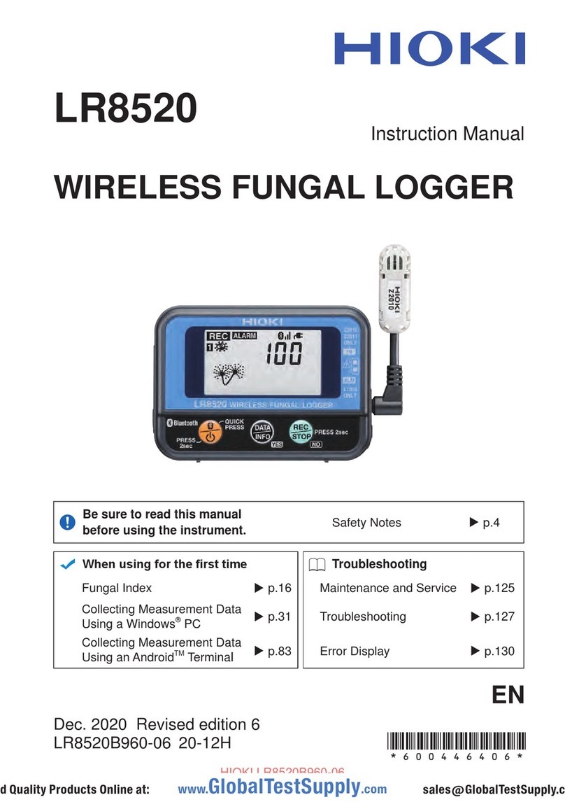
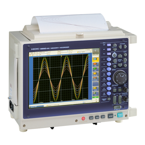
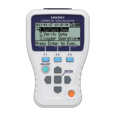
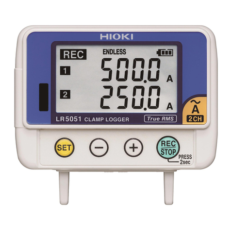
Hioki LR8450 Instruction manual

LR8450
LR8450-01
Quick Start Manual
MEMORY HiLOGGER
EN
Dec. 2020 Revised edition 2
LR8450A963-02 20-12H
Be sure to read this manual before using the instrument. p.6
When using the instrument for the rst time Troubleshooting
Convenient Functionality p.13
Maintenance and Service
p.93
Part Names and Functions; Screens p.23 Error messages p.97
Making Connections (Preparing for Measurement)
p.37 FAQ p.107
Settings and Operation p.75
HIOKI LR8450A963-02

HIOKI LR8450A963-02

i
2.8 Preparing the Wireless Modules ........72
Attaching the Z3230..................................72
Registering the wireless modules ..............73
Mounting the instrument on a wall or
other surface ............................................74
3 Settings and Operation 75
3.1 Basic Operation ....................................76
Switching among the main tabs.................76
Switching among the sub tabs...................76
Conguration Process...............................77
Changing and accepting settings...............78
Starting and stopping measurement ..........79
Formatting storage media .........................80
Saving data ..............................................81
Loading data.............................................81
Initialization (resetting the system).............82
Key lock (disabling keys)...........................82
3.2 Setting Example
(Measuring Temperature Using
Thermocouples)....................................83
4 Specications 87
4.1 Memory HiLogger Basic
Specications........................................87
4.2 Plug-in Module Specications ............88
U8550 Voltage/Temp Unit..........................88
U8551 Universal Unit ................................88
U8552 Voltage/Temp Unit..........................89
U8553 High Speed Voltage Unit ................89
U8554 Strain Unit .....................................89
LR8530 Wireless Voltage/Temp Unit..........90
LR8531 Wireless Universal Unit ................90
LR8532 Wireless Voltage/Temp Unit..........90
LR8533 Wireless High Speed
Voltage Unit ..............................................91
LR8534 Wireless Strain Unit .....................91
4.3 Wireless LAN Adapter
Specications........................................92
Z3230 Wireless LAN Adapter ....................92
5 Maintenance and
Service 93
5.1 Repairs, Calibration, and Cleaning ....93
5.2 Troubleshooting ....................................95
Before sending the instrument to be
repaired....................................................95
Error messages ........................................97
LED indicators (wireless modules)...........105
Contents
Introduction........................................................1
About the Notations Used in This Manual.....2
Checking Package Contents...........................4
Options (sold separately) ............................5
Safety .................................................................6
Operating Precautions .....................................8
Convenient Functionality ...............................13
Old-Versus-New Loggers ..............................20
1 Overview 21
1.1 Instrument Overview and
Features.................................................21
1.2 Part Names and Functions;
Screens..................................................23
LR8450/LR8450-01 Memory HiLogger ......23
Plug-in modules........................................30
Wireless modules .....................................31
1.3 Options...................................................33
Plug-in modules........................................33
Wireless modules .....................................33
Other options............................................34
1.4 Measurement Process.........................36
2 Making Connections
(Preparing for
Measurement) 37
2.1 Connecting Plug-in Modules...............38
2.2 Installing a Battery Pack......................40
2.3 Connecting the AC Adapter.................46
2.4 Connecting the External Power
Supply ....................................................48
2.5 Connecting the Cables ........................49
Pre-use inspection ....................................49
Connecting voltage cables and
thermocouples..........................................52
Connecting resistance temperature
detectors ..................................................54
Connecting the Humidity Sensor ...............55
Connecting a resistor ................................57
Connecting a strain gage or converter .......58
Connecting pulse input..............................61
Connecting alarm output ...........................62
Connecting voltage output.........................63
Connecting external control signals ...........65
2.6 Turning the Instrument On and O ....66
2.7 SD Memory Card and USB Drive ......68
Inserting and removing SD Memory
Cards .......................................................70
Inserting and removing USB Drives ...........71
Index
LR8450A963-02
HIOKI LR8450A963-02

1
Introduction
Introduction
Thank you for choosing the Hioki LR8450/LR8450-01 Memory HiLogger. To ensure your ability to
get the most out of this instrument over the long term, please read this manual carefully and keep it
available for future reference.
The LR8450-01 Memory HiLogger adds wireless LAN functionality to the LR8450.
This instrument comes with the following documentation. Please refer to these resources as
necessary in light of your specic application. Please review the separate “Operating Precautions”
before using the instrument.
Model Manual contents Printed
edition CD edition
Operating Precautions Information to ensure safe use of the instrument –
Precautions Concerning Use
of Equipment That Emits
Radio Waves
(LR8450-01 only)
Precautions relating to use of equipment that
emits radio waves, countries in which the
instrument has been certied, etc.
–
Quick Start Manual (this
manual)
Operating precautions, connection methods,
and basic operation
Instruction Manual Detailed information about functionality and
operation; specications and related knowledge –
Logger Utility*1
User Manual
Information about how to install and use the
computer application –
Communications
Commands*2User Manual
Explanation of communications commands for
controlling the instrument –
*1: For information about how to install and use the Logger Utility computer application, see “Logger Utility
User Manual” on the included CD (application disc).
*2: The instrument can be controlled by a LAN- or USB-connected computer.
For more information about the communications commands used to control the instrument, see
“Communications Commands User Manual” on the included CD (application disc).
Intended audience
This manual has been written for use by individuals who use the product or provide information
about how to use the product.
In explaining how to use the product, it assumes electrical knowledge (equivalent of the knowledge
possessed by a graduate of an electrical program at a technical high school).
Trademarks
• Microsoft, Windows, Excel, Internet Explorer, and Visual Basic are the registered trademarks or
trademarks of Microsoft Corporation in the U.S., Japan, and other countries.
• SD, SDHC Logos are trademarks of SD-3C LLC.
• Other products and company names are trade names, registered trademarks or trademarks of
their respective owners.
Screen font
• The typefaces included herein are solely developed by DynaComware Taiwan Inc.
HIOKI LR8450A963-02

2
About the Notations Used in This Manual
Safety notations
This manual classies seriousness of risks and hazard levels as described below.
DANGER Indicates an imminently hazardous situation that, if not avoided, will result in
death of or serious injury to the operator.
WARNING Indicates a potentially hazardous situation that, if not avoided, could result in
death of or serious injury to the operator.
CAUTION Indicates a potentially hazardous situation that, if not avoided, could result in
minor or moderate injury to the operator.
NOTICE Indicates the possibility of equipment damage.
IMPORTANT Indicates information or content that is particularly important from the
standpoint of operating or maintaining the instrument.
Indicates a high-voltage hazard. Failure to verify safety or improper handling of
the instrument could lead to electric shock, burns, or death.
Indicates an action that must not be performed.
Indicates action that must be performed.
Symbols on equipment
Indicates the need for caution or the presence of a hazard. For more information
about locations where this symbol appears on instrument components, see “Operating
Precautions” (p. 8), warning messages listed at the beginning of operating
instructions, and the document entitled “Operating Precautions” that comes with the
instrument.
Indicates an instrument that has been protected throughout.
Indicates whether the power is on or o.
Indicates the ground terminal.
Indicates direct current (DC).
Indicates alternating current (AC).
HIOKI LR8450A963-02

3
About the Notations Used in This Manual
Notations related to standards compliance
Indicates compliance with the Waste Electrical and Electronic Equipment (WEEE)
Directive in EU member nations.
Li-ion
Indicates that the instrument is targeted for recycling under the Act on the Promotion of
Eective Utilization of Resources.
Indicates that the instrument complies with standards imposed by EU directives.
Other notations
Indicates useful advice concerning instrument performance and operation.
*Instructs the reader to see below for additional information.
Indicates the default setting. When initialized, the instrument will revert to this value.
(p. ) Indicates the page number to reference.
Bold The names of control keys are printed in bold.
[ ] The names of user interface elements on the screen are enclosed in brackets ([ ]).
Windows Unless otherwise noted, the term “Windows” is used generically to refer to Windows 7,
Windows 8, and Windows 10.
S/s
For this instrument, the number of times the analog input signal is digitized is indicated
in samples per second (S/s).
Example: 20 Ms/s (20 megasamples per second) signies 20×106samples per second.
Accuracy
Hioki denes tolerances for measured values in terms of f.s. (full scale), as indicated below.
f.s.
Maximum display value, scale magnitude
Indicates the maximum display value or scale magnitude. Generally speaking, the f.s.
gure indicates the range in current use.
Example: f.s. for the 1 V range = 1 V
HIOKI LR8450A963-02

4
Checking Package Contents
When you receive the instrument, inspect it to ensure that no damage occurred during shipment.
Pay particular attention to included accessories, panel keys and switches, and terminals. If you
nd any damage or discover that the instrument does not perform as indicated in its specications,
please contact your authorized Hioki distributor or reseller.
Check to ensure proper package contents.
The instrument
LR8450/LR8450-01 Memory HiLogger
Accessories
Z1014 AC Adapter (with power cord)
See “2.3 Connecting the AC Adapter” (p. 46).
Operating Precautions (0990A903)
Precautions Concerning Use of Equipment That Emits
Radio Waves
(LR8450-01 only)
Quick Start Manual (this manual)
Logger Application Disc (CD)*
• Quick Start Manual
• Instruction Manual
• Logger Utility
• Logger Utility Instruction Manual
• Communications Commands Instruction Manual
USB cable
See “3.6 Acquiring Data with a Computer (PC)” in the
Instruction Manual.
*: The most recent version is available for download from Hioki’s website.
HIOKI LR8450A963-02

5
Checking Package Contents
Options (sold separately)
The options listed below are available for the instrument. See “Options” (p. 33).
To order an option, please contact your authorized Hioki distributor or reseller. Options are subject
to change. Check Hioki’s website for the latest information.
U8550 Voltage/Temp Unit
U8551 Universal Unit
U8552 Voltage/Temp Unit
U8553 High Speed Voltage Unit
U8554 Strain Unit
LR8530 Wireless Voltage/Temp Unit (LR8450-01 only)
LR8531 Wireless Universal Unit (LR8450-01 only)
LR8532 Wireless Voltage/Temp Unit (LR8450-01 only)
LR8533 Wireless High Speed Voltage Unit (LR8450-01 only)
LR8534 Wireless Strain Unit (LR8450-01 only)
Z1014 AC Adapter (accessory)
Z1007 Battery Pack
Z5040 Fixed Stand
C1012 Carrying Case
Z4001 SD Memory Card (2 GB)
Z4003 SD Memory Card (8 GB)
Z4006 USB Drive (16 GB)
9642 LAN Cable
HIOKI LR8450A963-02

6
Safety
Safety
The instrument and modules designed for use with the instrument have been designed in
accordance with the IEC 61010 safety standard, and their safety has been veried by means of
testing prior to shipment. However, failure to follow the information in this manual could render
safety-related functionality provided by the instrument ineective.
Please review the safety information below before using the instrument.
DANGER
Read this manual carefully and ensure you understand its contents
before using the instrument.
Improper use of the instrument could result in serious bodily injury or damage to the
instrument.
WARNING
If using an electrical measuring instrument for the rst time, seek
instruction from an individual with electrical measurement experience
rst.
Failure to do so may lead to electric shock, overheating, re, arcing due to a short-
circuit, or other hazards.
HIOKI LR8450A963-02

7
Safety
Measurement categories
IEC 61010 denes measurement categories to facilitate safe use of measuring instruments. Test
and measurement circuits designed to be connected to a main power supply circuit are classied
into three categories depending on the type of main power supply circuit.
DANGER
Do not use an instrument to measure a main power supply circuit
whose category exceeds the instrument’s rated measurement category.
Do not use an instrument that does not have a rated measurement
category to measure a main power supply circuit.
Doing so may result in serious bodily injury or damage to the instrument or other
equipment.
CAT II Applicable to test and measuring circuits connected directly to utilization points
(socket outlets and similar points) of the low-voltage mains installation.
Examples: Measurements on household appliances, portable tools, and similar
equipment, and on the consumer side only of socket-outlets in the xed
installation.
CAT III Applicable to test and measuring circuits connected to the distribution part of the
building’s low-voltage mains installation.
Examples: Measurements on distribution boards (including secondary meters),
photovoltaic panels, circuit breakers, wiring, including cables, bus-
bars, junction boxes, switches, socket-outlets in the xed installation,
and equipment for industrial use and some other equipment such as
stationary motors with permanent connection to the xed installation.
CAT IV Applicable to test and measuring circuits connected at the source of the building’s
low-voltage mains installation.
Examples: Measurements on devices installed before the main fuse or circuit
breaker in the building installation.
T Outlet
CAT II
CAT III
Indoor wiring
Energy meter
Distribution panel
Service inlet
Service wire
CAT IV
Fixed equipment
HIOKI LR8450A963-02

8
Operating Precautions
Be sure to follow the precautions listed below in order to use the instrument safely and in a manner
that allows it to function eectively.
Use of the instrument should conform not only to its specications, but also to the specications of
all accessories, options, and other equipment in use.
Checking safety prior to use
DANGER
Inspect the instrument and verify proper operation before use.
Use of the instrument while malfunctioning could result in serious bodily injury.
If you nd any damage, contact your authorized Hioki distributor or reseller.
For more information about inspections, see “Inspection of the instrument” (p. 49).
Installing the instrument
For more information about the instrument’s operating temperature and humidity range and its
storage temperature and humidity range, see “4 Specications” (p. 87).
WARNING
Do not install the instrument in locations such as the following:
•In locations where it would be subject to direct sunlight or high temperatures
•In locations where it would be exposed to corrosive or explosive gases
•In locations where it would be exposed to powerful electromagnetic radiation or
close to objects carrying an electric charge
•Close to inductive heating devices (high-frequency inductive heating devices,
IH cooktops, etc.)
•In locations characterized by a large amount of mechanical vibration
•In locations where it would be exposed to water, oil, chemicals, or solvents
•In locations where it would be exposed to high humidity or condensation
•In locations with an excessive amount of dust
Doing so could damage the instrument or cause it to malfunction, resulting in bodily
injury.
CAUTION
Do not place the instrument on an unstable stand or angled surface.
Doing so could cause the instrument to fall or overturn, resulting in bodily injury or
damage to the instrument.
Do not bend or pull on cables at temperatures of 0°C or lower.
Since cables become rigid, doing so could damage the insulation or cause a wire
break, resulting in electric shock.
HIOKI LR8450A963-02

9
Operating Precautions
Installing the instrument (continued)
NOTICE
Do not unplug data cables while the instrument is sending or receiving data.
Doing so could damage the instrument.
Turn o the instrument and computer before connecting or disconnecting data
cables.
Failure to do so could cause the instrument to malfunction or damage it.
Use the same ground for the instrument and computer.
Connecting data cables while there is a potential dierence between the instrument
and computer’s ground levels could cause the instrument to malfunction or damage it.
IMPORTANT
• Please take care not to change the ambient temperature around the terminal blocks of
measurement modules. If the terminal blocks are subject to wind, such as that blown from a
ventilator or an air conditioner, measurement errors will arise during temperature measurement
with thermocouples.
• When moving the instrument to a location with a signicantly dierent temperature, allow the
instrument to sit for at least 60 minutes before starting measurement.
Do not block vent openings. (Leave at least 5 cm of space on the left and right sides of the
instrument in order to keep its temperature from rising.)
At least 5 cm At least 5 cm
The instrument is classied as a Class A device under the EN 61326 standard. Use of the
instrument in a residential setting such as a neighborhood could interfere with reception of radio
and television broadcasts. If you encounter this issue, take steps as appropriate to address it.
Installing the wireless modules
Place the wireless module in either of the following orientations.
• Horizontal orientation: Place with its front side (the input terminals) up.
• Vertical orientation: Place with its upper side (the Z3230 attached) up.
If the wireless module is placed in other orientations, the system may yield measured values that
do not meet the accuracy specications.
Horizontal orientation Vertical orientation
HIOKI LR8450A963-02

10
Operating Precautions
Measurement precautions
DANGER
Do not input a voltage that exceeds the measurement module’s
maximum input voltage, maximum rated terminal-to-ground voltage, or
maximum rated channel-to-channel voltage to any channel.
Do not input a voltage to a resistance measurement terminal.
Measurement modules have dierent maximum input voltages, maximum rated
terminal-to-ground voltages, and maximum rated channel-to-channel voltages. For
more information about maximum input voltages, maximum rated terminal-to-ground
voltages, and maximum rated channel-to-channel voltages, see “Specications”
(p. 87).
Doing so could cause electric shock or damage the instrument.
Do not use the instrument or measurement modules to measure a main
power supply circuit.
The U8550, U8551, U8552, U8553, LR8530, LR8531, LR8532, and LR8533
measurement modules have terminal-to-ground voltages that qualify as CAT II, but
they cannot be used to perform CAT II, CAT III, or CAT IV measurement.
Never input a CAT II, CAT III, or CAT IV voltage across measurement terminals.
Doing so could cause electric shock or damage the instrument.
Turn o power to the circuit under measurement before performing
measurement.
Failure to do so could cause electric shock or damage the instrument.
WARNING
Do not allow the instrument to get wet.
Do not operate the instrument with wet hands.
Doing so could cause electric shock.
Eect of induction potential
Displayed values can frequently uctuate due to induction potential even when no
voltage is applied. This, however, is not a malfunction.
HIOKI LR8450A963-02

11
Operating Precautions
Shipping precautions
Store packaging materials for future use. You will need the packaging materials when shipping the
instrument.
NOTICE
Do not subject the instrument to vibration or mechanical shock while
transporting or handling it.
Do not drop the instrument.
Doing so could damage the instrument.
When transporting the Z1007 Battery Pack on an aircraft
• The Z1007 Battery Pack uses rechargeable lithium-ion batteries.
• The transport of lithium-ion batteries by air is subject to regulations in accordance with United
Nations recommendations.
• If you need to repair or calibrate any device that uses the Z1007 Battery Pack or to transport such
devices by air, contact your authorized Hioki distributor or reseller.
Precautions related to disc usage
• Exercise care to keep the recording surface of the disc free of dirt and damage. If you need to
label the disc, for example with text, use a marker with a soft tip.
• Store discs in protective cases. Avoid exposing discs to direct sunlight, high temperatures, or high
humidity.
• Hioki is not liable for any computer system issues that arise in connection with the use of this
disc.
HIOKI LR8450A963-02

12
Operating Precautions
Wireless LAN
The LR8450-01 Memory HiLogger and Z3230 Wireless LAN Adapter use radio communications
in the 2.4 GHz band. No regulatory permit is necessary to use the product, but caution should be
exercised with regard to the following:
DANGER
Do not use the instrument in proximity to medical devices such as
pacemakers.
Radio waves from the product may aect operation of the pacemaker or other
medical device, causing it to malfunction or damaging it.
WARNING
Do not use the instrument with medical equipment, nuclear power
equipment or devices, aerospace equipment, transport equipment or
devices, or other equipment or devices being used in applications that
aect human life, or with equipment, devices, or systems that require
an advanced level of reliability.
Hioki is not liable for any bodily injury or damage that arise as a result of the use of
the product in such applications.
NOTICE
Do not use the LR8450-01 and its wireless modules near other wireless
communications devices that use the 2.4 GHz frequency band.
Doing so may result in communications instability or aect the operation of other
devices.
Install the LR8450-01 and any wireless modules (Z3230 Wireless LAN Adapters)
so that they are not more than roughly 30 m apart.
Install the LR8450-01 and any wireless modules so that there are no
obstructions (walls, metal materials, etc.) between them.
Failure to do so may result in communications instability or reduce the
communications range.
• Communications between the LR8450-01 and its wireless modules (Z3230 Wireless LAN
Adapters) are encrypted, but the condentiality of information sent and received is not guaranteed.
Hioki is not liable for any leaks of measured values caused by wireless communications.
• The LR8450-01 and its wireless modules (Z3230 Wireless LAN Adapters) give o radio-wave
radiation. Use of radio communications requires a permit in the country of use. Use of the
instrument outside the countries and regions listed in the included “Precautions Concerning Use
of Equipment That Emits Radio Waves” may constitute a violation of applicable laws, resulting in
penalties.
• Placing the LR8450-01 and its wireless modules (Z3230 Wireless LAN Adapters) on the oor or
ground will reduce the communications range. The communications range can be extended by
moving the devices away from the oor or ground, for example by placing them on a workbench
or stand.
HIOKI LR8450A963-02

13
Convenient Functionality
This section introduces convenient functionality provided by the instrument and indicates where to
look for more information.
When you want to capture sudden phenomena
It’s hard to search for anomalies in a long recording. You want to record only
anomalies.
Trigger function
See “2 Trigger Function” in the Instruction Manual.
Specify the level that indicates an anomaly so that the instrument starts recording when that
condition is satised.
You can use the trigger function to control when to start and stop recording.
Recording will start when the input signal
reaches or exceeds the trigger level.
High data volume
Trigger level
Data where required only Recording
time
Recording
time
Recording
time
When you want to view data before an issue occurs
Why did the issue occur? You want to view the waveform before an anomaly occurred.
Pre-trigger function
See “2.2 Enabling the Trigger Function” in the Instruction Manual.
You can also record data before trigger conditions are satised.
Data preceding an anomaly is useful when you need to analyze the cause of an issue.
Trigger level
Analyze the cause based on
data preceding anomaly.
Recording
time
Recording
time
Recording
time
Pre-trigger Pre-trigger Pre-trigger
HIOKI LR8450A963-02

14
Convenient Functionality
When you want to view waveforms, numerical values, and
comments at the same time
You want to view waveforms and numerical values at the same time. You want to
display comments that identify the data.
Switching the waveform screen
See “Waveform display” in the Instruction Manual.
You can switch the waveform screen with the WAVE key.
This feature also lets you display numerical values and comments along with waveforms.
Waveform Numerical values
Comments
When you want to read values from waveforms
You want to read values from waveforms. You also want to ascertain the potential
dierence or time dierence between two points.
A/B cursors
See “1.13 Using the A/B Cursors” in the Instruction Manual.
The A/B cursors let you read measured values and times from waveforms.
You can also read the potential dierence and time dierence between the A cursor and the
B cursor.
Values read with A/B cursors
B cursor
A cursor
HIOKI LR8450A963-02

15
Convenient Functionality
When you want to ascertain the characteristics of the measured
waveform
You want to ascertain the characteristics of a waveform, for example its maximum and
minimum values.
Numerical calculation function
See “6.1 Performing Numerical Calculations” in the Instruction Manual.
This function lets you ascertain the characteristics of measured waveforms using numerical
calculations.
You can calculate any 10 values out of 13 available choices, including maximum value,
minimum value, and average value.
Maximum value
Minimum value
P-P value
Numerical calculation
When you want to record only the rise in temperature
You want to know how much a temperature reading rose from the ambient
temperature.
Waveform calculation function
See “6.2 Performing Waveform Calculations” in the Instruction Manual.
This function lets you measure the temperature of the measurement target using U1-1 and
the ambient temperature using U1-2.
You can record the measurement target’s rise in temperature using the following waveform
calculation: W1 = U1-1 − U1-2
U1-1: Temperature of measurement target
U1-2: Ambient temperature
W1: Rise in temperature
(Waveform after waveform processing)
HIOKI LR8450A963-02

16
Convenient Functionality
When you want to stop a piece of equipment if it becomes too hot
You want to monitor the temperature of a piece of equipment and halt its operation if it
becomes too hot.
Alarm output function
See “4 Alarm (Alarm Output)” in the Instruction Manual.
This function lets you set a threshold and then output an alarm signal if the input signal
reaches or exceeds that threshold.
Alarm output can be used to communicate the alarm to a piece of equipment or to control a
warning lamp.
Alarm
Alarm
Alarm
Level
Time
Slope
When the rate of
change of the input
signal continues to
exceed the specied
rate of change per
time during the period
of the set recording
time, an alarm will
output.
When you want to control the LR8450 from a computer
An LR8450 is located in a lab. You want to control it from a computer that is outside
the lab.
Logger Utility
See “9.1 Using the Logger Utility” in the Instruction Manual.
You can use the included Logger Utility application.
You can control an LR8450 from a computer that is connected via a LAN or USB.
LAN/USB
Logger Utility screen
HIOKI LR8450A963-02
Other manuals for LR8450
6
This manual suits for next models
1
Table of contents
Other Hioki Data Logger manuals

Hioki
Hioki LR5031 User manual

Hioki
Hioki LR5011 User manual

Hioki
Hioki LR8400-20 User manual

Hioki
Hioki HiCORDER MR8880 User manual

Hioki
Hioki LR5041 User manual

Hioki
Hioki LR8520 User manual

Hioki
Hioki 3638-20 User manual

Hioki
Hioki LR8431-20 User manual

Hioki
Hioki LR8450 User manual

Hioki
Hioki LR8431-20 User manual

Hioki
Hioki LR8512 User manual

Hioki
Hioki Hioki Instruction manual

Hioki
Hioki lr5001 User manual

Hioki
Hioki LR8410-20 User manual

Hioki
Hioki 3639-20 User manual

Hioki
Hioki 3640-20 User manual

Hioki
Hioki LR8101 User guide

Hioki
Hioki LR5051-20 User manual

Hioki
Hioki LR5092-20 User manual

Hioki
Hioki HiLogger 3145-20 User manual