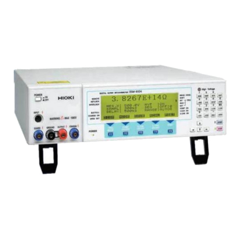
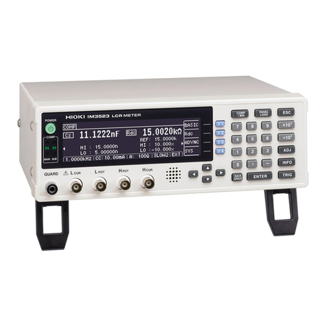
Hioki IM3533 User manual

IM3533・IM3533-01 LCR METER Instruction Manual
Instruction Manual
IM3533-01
LCR METER
IM3533
September 2012 Revised edition 1 IM3533A981-01 12-09H


Contents
i
Contents
Introduction.....................................................1
Verifying Package Contents...........................1
Safety Information..........................................3
Operating Precautions....................................5
Chapter 1 Overview 9
1.1 Product Overview Features .................9
1.2 Names and Functions of Parts ...........10
1.3 Screen Configuration and Operation .12
1.3.1 Initial Screen ......................................12
1.3.2 Measurement Mode Selection Screen 13
1.3.3 Advanced Settings Screen .................14
1.3.4 Compensation Settings Screen .........24
1.3.5 System Settings Screen .....................25
1.3.6 Save Settings Screen ........................27
1.3.7 Parameter Settings Screen ................28
Chapter 2 Measurement
Preparations 29
2.1 Preparation Flowchart ........................29
2.2 Pre-Operation Inspection ...................30
2.3 Connecting the Power Cord ...............31
2.4 Connecting the Measurement Cables,
Probes, or Fixture ..............................32
2.5 Connecting a Temperature Probe ......33
2.6 Connecting an Interface .....................34
2.7 Turning the Power On and Off ...........35
Chapter 3 Measurement
Example 37
3.1 When LCR Mode ...............................37
3.2 When ANALYZER Mode
(IM3533-01 only) ................................39
3.3 When TRANSFORMER Mode ...........41
Chapter 4 LCR Function 45
4.1 About LCR function ............................45
4.1.1 Measurement screen ..........................45
4.1.2 Setting Display Parameters ................47
4.1.3 Enlarging Display of Measurement
Values ................................................49
4.2 Setting Basic Settings of
Measurement Conditions ...................50
4.2.1 Setting the Measurement frequency ..50
4.2.2 Setting the Measurement signal level 52
4.2.3 Limiting the Voltage and Current Applied
to the Sample (Limit Values) ..............56
4.2.4 Setting the DC bias ............................58
4.2.5 PerformMeasurementswithUser-defined
Timing (Trigger Measurement) ...........60
4.2.6 Setting the Measurement Range ........62
Setting the method for determining the
measurement range
(AUTO, HOLD, JUDGE SYNC) ............... 62
Low Z High Accuracy Mode ..................... 71
4.2.7 Setting the Measurement speed ........73
4.2.8 Displaying Average Values
(Averaging Set) ..................................74
4.2.9 SettingtheDelayTimeuntilMeasurement
Data is Captured (Trigger Delay) .......76
4.2.10 Applying the Signal to the Sample
during Measurement Only (Trigger
Synchronous Output Function) ...........77
4.3 Setting DC Resistance Measurement 80
4.3.1 Configuring the Temperature
Correction Function ............................81
4.3.2 Setting the DC Measurement Delay
Time (DC Delay) .................................83
4.3.3 Setting the Offset Measurement Delay
Time (Adjustment Delay) ....................85
4.3.4 Setting the Line Frequency ................87
4.3.5 Setting the Measurement Range ........88
Setting the method for determining the
measurement range
(HOLD, AUTO, JUDGE SYNC) ............... 88
Low Z High Accuracy Mode ..................... 96
4.3.6 Setting the Measurement Speed ........98
4.3.7 Displaying Average Values
(Average set) ......................................99
1
2
3
4
5
6
7
8
9
10
ït
ò^
ç€
à¯
11
12

Contents
ii
4.4 Judging Measurement Results .........100
4.4.1 Judging with Upper and Lower Limit
Values (Comparator Measurement
Mode) ...............................................102
Setting the Upper or Lower Limit Value as
an Absolute Value (ABS)
(Absolute Value Mode) .......................... 104
Setting the Upper or Lower Limit Value as a
Percentage (%) Relative to a Reference
Value (Percentage Mode) ...................... 105
Setting Upper and Lower Limit Values as
(%) Values Relative to the Offset from
the Reference Value (Deviation Percentage
Mode) ..................................................... 107
4.4.2 Classifying Measurement Results
(BIN Measurement) ..........................109
Setting the Upper or Lower Limit Value as
an Absolute Value (ABS)
(Absolute Value mode) .......................... 111
Setting the Upper or Lower Limit Value as
a Percentage (%) Relative to a Reference
Value (Percentage mode) ...................... 114
Setting Upper and Lower Limit Values as
(%) Values Relative to the Offset from
the Reference Value (Deviation Percentage
Mode) ..................................................... 117
4.5 Setting Application Settings ..............120
4.5.1 Setting Measurement Conditions for
Individual Measurement Ranges
(Range Synchronization Function) ...120
4.5.2 Setting the Detection Signal Waveform
Averaging Count (Waveform Averaging
Function) ..........................................128
4.5.3 Detecting OPEN during 2-terminal
Measurement
(HIGH-Z Reject Function) .................130
4.5.4 Checking Contact Defects and the Con-
tact State (Contact Check Function) 132
4.5.5 Setting the Delay Time from the Output
ofComparatorandBINJudgmentResults
until Output of EOM (LOW) and Resetting
Judgment Results .............................134
4.5.6 Enabling Trigger Input for during
Measurement and Setting the Valid
Edge of Trigger Input ........................136
4.5.7 Setting the EOM Output Method ......137
4.5.8 Saving Measurement Results
(Memory function) ............................138
4.5.9 Setting the Number of Display Digits 140
4.5.10Setting the LCD to ON/OFF .............142
4.5.11Setting Operation Sounds
(Beep Sounds) .................................143
4.5.12Disabling Key Operation
(Key-lock Function) .......................... 144
4.5.13Initializing (System Reset) .............. 147
Chapter 5 ANALYZER Function
(IM3533-01) 149
5.1 About ANALYZER function ..............149
5.1.1 Measurement screen ....................... 149
5.2 Setting Basic Settings of
Measurement ................................... 150
5.2.1 Setting the measurement parameter 150
5.2.2 Setting the Trigger ...........................151
5.2.3 Setting the Display Timing ............... 152
5.2.4 Setting the Trigger Delay ................. 153
5.2.5 Setting Sweep Points ....................... 155
5.2.6 Setting the Measurement Signal
Level ................................................ 158
5.2.7 Setting the Measurement Range ..... 160
Setting the method for determining the
measurement range (AUTO, HOLD) ......160
Low Z high accuracy mode .................... 164
5.2.8 Setting the Measurement Speed ..... 166
5.2.9 Displaying as Average Values
(Average set) ................................... 167
5.2.10Setting the Point Delay ...................168
5.2.11Setting the DC Bias .........................169
5.3 Application Settings ......................... 171
5.3.1 Applying the Signal to the Sample Only
during Measurement (Trigger Synchro-
nous Output Function) .....................171
5.3.2 Setting the Detection Signal Waveform
Averaging Count (Waveform Averaging
Function) .......................................... 173
5.3.3 Detecting OPEN during 2-terminal
Measurement
(HIGH-Z Reject Function) ................ 175
5.3.4 Checking Contact Defects and the
Contact State (Contact Check
Function) .......................................... 177
5.3.5 Saving Measurement Results
(Memory function) ............................ 179
5.3.6 AUTO Range Limit Function ............182
5.3.7 Setting the LCD to ON/OFF .............184
5.3.8 Setting Operation Sounds
(Beep Sounds) ................................. 185
Contents
iii
Appendix
Index
5.3.9 Disabling Key Operation
(Key-lock Function) ..........................186
5.3.10Enabling Trigger Input for during Mea-
surement and Setting the Valid Edge of
Trigger Input .....................................189
5.3.11Setting the EOM Output Method .....190
5.3.12Initializing (System Reset) ...............191
Chapter 6 TRANSFORMER
Function 193
6.1 About TRANSFORMER function .....193
6.1.1 Measurement screen .......................193
6.1.2 Measurement Methods ....................194
6.1.3 Setting the measurement parameter 196
6.1.4 Setting Calculation Parameters .......197
6.2 Setting Basic Settings of Measurement
Conditions ........................................198
6.3 Judging with Upper and Lower Limit
Values (Comparator Measurement
Mode) ...............................................199
Setting the Upper or Lower Limit Value as
an Absolute Value (ABS)
(Absolute Value Mode) ...........................202
Setting the Upper or Lower Limit Value as
a Percentage (%) Relative to a Reference
Value (Percentage Mode) .......................203
Setting Upper and Lower Limit Values as
(%) Values Relative to the Offset from the
Reference Value
(Deviation Percentage Mode) .................205
6.4 Setting Application Settings .............207
Chapter 7 CONTINUOUS
Measurement
Function 209
7.1 About CONTINUOUS Measurement
Function ...........................................209
7.1.1 Measurement screen .......................209
7.2 Configuring CONTINUOUS
Measurement Basic Settings ...........210
7.3 Performing CONTINUOUS
Measurement ...................................211
7.4 Checking CONTINUOUS Measurement
Results .............................................212
7.5 Configuring CONTINUOUS
Measurement Application Settings .. 213
7.5.1 Setting the Display Timing ............... 213
7.5.2 Setting the LCD to ON/OFF ............. 214
Chapter 8 Error
Compensation 215
8.1 Setting Open Circuit Compensation 215
8.1.1 All Compensation ............................ 216
8.1.2 Spot Compensation ......................... 220
8.2 Short Circuit Compensation ............. 224
8.2.1 All Compensation ............................ 226
8.2.2 Spot Compensation ......................... 228
8.3 Compensating Values to Match
Reference Values
(Load Compensation) ...................... 232
8.4 Compensating Measurement Cable
Errors (Cable Length Compensation)
......................................................... 245
8.5 Calculating Values (Scaling) ............ 246
Chapter 9 Saving and Loading
Panel Information
249
9.1 Saving Measurement Conditions
(Panel Save Function) ..................... 251
9.2 Loading Measurement Conditions
(Panel Load Function) ..................... 256
9.3 Changing a Panel Name ................. 258
9.4 Deleting a Panel .............................. 260
Chapter 10 Setting the
SYSTEM 263
10.1 Setting the Interface ........................ 263
10.2 Checking the Version of the
Instrument ....................................... 264
10.3 Self Checks (Self Diagnosis) ........... 265
10.4 Setting the Date and Time ............... 272
1
2
3
4
5
6
7
8
9
10
11
12
14
13

Contents
iv
Chapter 11 Using USB Flash
Drive 273
11.1 Inserting and Removing USB flash
drive ..................................................274
11.2 About the File Operation Screen ......275
11.3 About the File Save Setting Screen .276
11.4 Saving Measurement Data ...............277
Saving Measurement Data .................... 277
Saving a Copy of the Screen ................. 287
Checking the Contents of Files .............. 290
Changing the Save Folder ..................... 291
11.5 Saving Instrument Settings ..............293
Saving Instrument Settings .................... 293
Saving All Settings of Instrument
(ALL SAVE Function) ............................. 295
11.6 Loading Instrument Settings .............297
Loading instrument settings ................... 297
Loading all settings saved on a USB flash
drive ....................................................... 300
(ALL LOAD Function) ............................. 300
11.7 File and Folder Operations ...............302
Formatting a USB Flash Drive ............... 302
Deleting Files and Folders ..................... 304
Creating Folders .................................... 305
Displaying the USB Flash Drive
Information ............................................. 307
Chapter 12 External Control309
12.1 External Input/Output Connector and
Signals 309
Connector Type and Signal Pinouts ...... 310
Signal function details ............................ 316
12.2 Timing Chart .....................................318
12.2.1LCR Mode .......................................318
12.2.2ANALYZER Mode (IM3533-01 only) 321
12.2.3TRANSFORMER Mode ...................322
12.2.4CONTINUOUS Measurement Mode 323
12.3 Internal Circuitry ...............................325
Electrical Specifications ......................... 326
Connection Examples ............................ 327
12.4 External I/O Settings ........................328
Setting Delay Time from Output of Compara-
tor and BIN Judgment Results until Output
of EOM (LOW) ....................................... 328
Setting Reset of Judgment Results ........ 328
Enabling Trigger Input for during
Measurement .........................................328
Setting Valid Edge of Trigger Input ........328
12.5 External Control Q&A ...................... 329
12.6 Measurement Using a Computer ..... 329
Chapter 13Printing 331
13.1 Connecting the Printer ..................... 331
Connecting the Printer to the Instrument 332
13.2 Instrument and Printer Settings ....... 333
Make Instrument Settings ......................333
13.3 Printing ............................................. 334
Chapter 14Specifications 337
14.1 General Specifications ..................... 337
14.2 Measurement Range and Accuracy 342
14.3 About Measurement Times and
Measurement Speed ....................... 350
Chapter 15Maintenance and
Service 353
15.1 Inspection, Repair and Cleaning ...... 353
15.2 Troubleshooting ............................... 355
15.3 Error display ..................................... 360
15.4 Discarding the Instrument ................ 362
Appendix A 1
Appendix1 Measurement Parameters and
Calculation Formula .................A 1
Appendix2 Measurement of High Impedance
Components.............................A 3
Appendix3 Measurement of In-circuit Compo-
nents.........................................A 4
Appendix4 Countermeasures Against Incorpo-
ration of External Noise............A 5
Appendix4.1Countermeasures Against Incor-
poration of Noise from the Power
Line ..........................................A 5

Contents
v
Appendix4.2Countermeasures Against Noise
from the measurement Cables A 6
Appendix5 Supplying DC Bias....................A 7
Appendix5.1How to Supply a DC Bias
Voltage .....................................A 7
Appendix5.2How to Supply a DC Bias
Current .....................................A 9
Appendix6 The Residual Charge Protection
Function..................................A 10
Appendix7 Series Equivalent Circuit Mode
and Parallel Equivalent Circuit
Mode.......................................A 11
Appendix8 Open Circuit Compensation and
Short Circuit Compensation....A 12
Appendix9 Temperature Correction
Function (TC)..........................A 13
Appendix10Rack Mounting .......................A 15
Appendix11Dimensional Diagram.............A 17
Appendix12Initial Settings Table...............A 18
Appendix 13Device Compliance
Statement ...............................A 23
Index Index 1

Contents
vi

Introduction
1
Thank you for purchasing the HIOKI Model IM3533, IM3533-01 LCR Meter. To obtain maximum perfor-
mance from the instrument, please read this manual first, and keep it handy for future reference.
When you receive the instrument, inspect it carefully to ensure that no damage occurred during shipping.
In particular, check the accessories, panel switches, and connectors. If damage is evident, or if it fails to
operate according to the specifications, contact your authorized Hioki distributor or reseller.
Transporting the instrument
Use the original packing materials when transporting the instrument, if possible.
See "Transporting the instrument" (p. 354)
Introduction
Verifying Package Contents
Confirm that these contents are provided.
IM3533 or IM3533-01 LCR Meter...........1 Instruction Manual (This document) ...... 1
Power Cord (2-line + ground).................1
LCR Application Disk ............................ 1
(Communications instruction manual [PDF
format], explanation of communications
commands, USB driver, sample application)
The latest version can be downloaded
from our web site.
• Probes, fixture are not supplied with the instrument as standard equipment. You should
order them separately, according to requirements.
• The instrument ships from the factory configured as described in "Appendix12 Initial Set-
tings Table"(p. A18).

Verifying Package Contents
2
Options
For more information, contact the store (distributor) from which you purchased the instrument or your nearest
HIOKI sales office.
Measurable range: DC to 200 kHz
Maximum voltage: ±42 Vpeak (AC+DC)
Maximum current: ±1 Apeak (AC+DC)
Measurement terminal hole diameter: 0.3 mm to 5 mm
L2000 4-terminal Probe
Alligator-clip-type measure-
ment probes. These general-
purposedual-electrode clipsfit
a wide range of conductor
thicknesses.
Measurable range: DC to 5 MHz
Maximum voltage: ±42 Vpeak (AC+DC)
Maximum current: ±1 Apeak (AC+DC)
Measurement terminal hole diameter: 0.3 mm to 5 mm
9140-10 4-terminal Probe
Measurable range: DC to 5 MHz
Maximum voltage: ±DC30 V
Electrode tip spacing: 0.3 mm to approx. 6 mm
Measurable range: DC to 1 MHz
Maximumvoltage:DC±40V(42 Vpeak(Measurementsignal+bias voltage))
Maximum current: 1 Apeak (Measurement signal + bias current)
Measurement terminal hole diameter: 0.3 mm to 2 mm
Rubber-sheathed alligator
clip type
9500-10 4-terminal Probe
Pincher type
9143-10 Pincher Probe
9261-10 Test Fixture
Measurable range: 42 Hz to 5 MHz
Maximum applied voltage: DC±40 V
Test sample dimensions: Lead diameter of 0.3 mm to 2 mm
Lead pitch of 5 mm or more
This fixture is for measuring
lead components. (less than
10 mresidual resistance
after zero adjustment)
9262 Test Fixture
easurable range: DC to 5 MHz
Maximum applied voltage: DC±40 V
Measurement terminal hole diameter: 0.3 mm to 1.5 mm
9263 SMD Test Fixture
This fixture is for measuring chip
components. (less than 10 m
residual resistance after zero ad-
justment)
Measurable range: DC to 120 MHz
Maximum applied voltage: DC±40 V
Test sample width of 3.5±0.5 mm or less
Measurable range: DC to 5 MHz
Maximum applied voltage: DC±40 V
Test sample dimensions: Test sample width of 1 to 10 mm
9677 SMD Test Fixture
9268-10 DC Bias Voltage Unit
Measurable range: 40 Hz to 2 MHz
Maximum applied current: DC2 A
Measurable range: 40 Hz to 5 MHz
Maximum applied voltage: DC±40 V
9269-10 DC Bias Current Unit
This fixture is for the lower
electrode.
Measurable range: DC to 120 MHz
Maximum applied voltage: DC±40 V
Test sample dimensions: Test sample width of 1 to 4 mm
Test sample height of 1.5 mm or less
Platinum resistance bulb (Pt100), waterproof design
(EN60529:1991,IP67)
Measurable range: -10.0°C to 99.9°C
Tip diameter: 2.3 mm
Cord length: 1 m
9699 SMD Test Fixture 9478 Temperature Probe
Z3000
GP-IB Interface Z3001
RS-232C Interface Z3002
LAN Interface

Safety Information
3
This manual contains information and warnings essential for safe operation of the instrument and for main-
taining it in safe operating condition. Before using it, be sure to carefully read the following safety precautions.
The following symbols in this manual indicate the relative importance of cautions and warnings.
Safety Information
This instrument is designed to comply with IEC 61010 Safety Standards, and has
been thoroughly tested for safety prior to shipment. However, mishandling during
use could result in injury or death, as well as damage to the instrument. However,
using the instrument in a way not described in this manual may negate the provided
safety features.
Be certain that you understand the instructions and precautions in the manual before
use. We disclaim any responsibility for accidents or injuries not resulting directly
from instrument defects.
Safety Symbols
In the manual, the symbol indicates particularly important information that the user should
read before using the instrument.
The symbol printed on the product indicates that the user should refer to a corresponding
topic in the manual (marked with the symbol) before using the relevant function.
Indicates AC (Alternating Current).
Indicates the ON side of the power switch.
Indicates the OFF side of the power switch.
Indicates that incorrect operation presents a significant hazard that could result in seri-
ous injury or death to the user.
Indicates that incorrect operation presents a significant hazard that could result in seri-
ous injury or death to the user.
Indicates that incorrect operation presents a possibility of injury to the user or damage
to the product.
Advisory items related to performance or correct operation of the product.
Symbols for Various Standards
WEEE marking:
This symbol indicates that the electrical and electronic appliance is put on the EU market
after August 13, 2005, and producers of the Member States are required to display it on the
appliance under Article 11.2 of Directive 2002/96/EC (WEEE).
This symbol indicates that the product conforms to safety regulations set out by the EC Direc-
tive.

Safety Information
4
Accuracy
We define measurement tolerances in terms of f.s. (full scale), rdg. (reading) and dgt. (digit) values, with
the following meanings:
To ensure safe operation of measurement instruments, IEC 61010 establishes safety standards for vari-
ous electrical environments, categorized as CAT II to CAT IV, and called measurement categories. These
are defined as follows.
Using a measurement instrument in an nvironment esignated with a higher-numbered category than that
for which the instrument is rated could result in a severe accident, and must be carefully avoided.
Notation
Symbols in this manual
Indicates the prohibited action.
p. ) Indicates the location of reference information.
* Indicates that descriptive information is provided below.
[ ] Menus, commands, dialogs, buttons in a dialog, and other names on the screen and the
keys are indicated in brackets.
CURSOR
(Bold character) Bold characters within the text indicate operating key labels.
Windows Unless otherwise specified, “Windows” represents Windows 95, 98, Me, Widows NT4.0,
Windows 2000, Windows XP, Windows Vista or Windows 7.
Dialogue Dialogue box represents a Windows dialog box.
f.s. (maximum display value or
scale length) The maximum displayable value or scale length. This is usually the name
of the currently selected range.
rdg. (reading or displayed value) Thevaluecurrentlybeingmeasuredandindicatedonthemeasuringinstrument.
dgt. (resolution) The smallest displayable unit on a digital measuring instrument, i.e., the in-
put value that causes the digital display to show a "1" as the least-signifi-
cant digit.
Measurement categories
CAT II Primary electrical circuits in equipment connected to an AC electrical outlet by a power cord (portable
tools, household appliances, etc.) CAT II covers directly measuring electrical outlet receptacles.
CAT III Primaryelectricalcircuitsofheavy equipment(fixedinstallations)connecteddirectlytothedistribution
panel, and feeders from the distribution panel to outlets.
CAT IV The circuit from the service drop to the service entrance, and to the power meter and primary over-
current protection device (distribution panel).

Operating Precautions
5
Follow these precautions to ensure safe operation and to obtain the full benefits of the various functions.
Before using the instrument for the first time, verify that it operates normally to ensure the no damage
occurred during storage or shipping. If you find any damage, contact your authorized Hioki distributor or
reseller.
Operating temperature and humidity:
0 to 40°C (32 to 104°F), 20 to 80% RH or less, Indoors (non-condensating)
Storing temperature and humidity:
-10 to 55°C (14 to 131°F) 20 to 80% RH or less, Indoors (non-condensating)
Temperature and humidity range for guaranteed accuracy, 23±5°C, RH or less
To prevent overheating, be sure to leave the specified clearances around the instrument.
• The instrument should be operated only with the bottom or rear side downwards.
• The instrument must not be placed on an unstable table or tilted surface.
• Vents must not be obstructed.
Operating Precautions
Preliminary Checks
Before using the instrument, make sure that the insulation on the voltage cords is
undamaged and that no bare conductors are improperly exposed. Using the instru-
ment in such conditions could cause an electric shock, so contact your dealer or
Hioki representative for replacements.
Instrument Installation
Avoid the following locations that could cause an accident or damage to the instrument.
Exposed to direct sunlight
Exposed to high temperature In the presence of corrosive or explosive
gases
Exposed to water, oil, other chemi-
cals, or solvents
Exposed to high humidity or conden-
sation
Exposed to strong electromagnetic fields
Near electromagnetic radiators
Exposed to high levels of particulate
dust Near induction heating systems
(e.g., high-frequency induction heating
systems and IH cooking utensils)
Subject to vibration
The instrument can be used with the stand (p. 11).
It can also be rack-mounted (p.A15).
50 mm or more 10 mm or more
Rear
50 mm or more Vents

Operating Precautions
6
Hioki disclaims responsibility for any direct or indirect damages that may occur when this instrument has
been combined with other devices by a systems integrator prior to sale, or when it is resold.
Shipping precautions
Handling the Instrument
• To avoid electric shock, do not remove the instrument's case. The internal compo-
nents of the instrument carry high voltages and may become very hot during oper-
ation.
• Do not allow the instrument to get wet, and do not take measurements with wet
hands. This may cause an electric shock.
•If the instrument exhibits abnormal operation or display during use, review the informa-
tion in "Inspection, Repair and Cleaning" (p. 353) and "Error display" (p. 360) before con-
tacting your dealer or Hioki representative. Note that the instrument may be damaged if
the applied voltage or current exceeds the measurement range.
•This instrument is not designed to be entirely water- or dust-proof. Do not use it in an
especially dusty environment, nor where it might be splashed with liquid. This may cause
damage.
•To avoid damage to the instrument, protect it from physical shock when transporting and
handling. Be especially careful to avoid physical shock from dropping.
•Do not apply heavy downward pressure with the stand extended. The stand could be
damaged.
•Do not use excessive force on the touch panel, and do not use sharp objects that could
damage the touch screen.
•After use, always turn OFF the power.
This instrument may cause interference if used in residential areas. Such use must be
avoided unless the user takes special measures to reduce electromagnetic emissions to
prevent interference to the reception of radio and television broadcasts.
Before Turning Power On
•Before turning the instrument on, make sure the supply voltage matches that indicated
on its power connector. Connection to an improper supply voltage may damage the
instrument and present an electrical hazard.
•Be careful to avoid connecting the supply voltage improperly. Doing so may damage the
instrument's internal circuitry.
•To avoid electrical accidents and to maintain the safety specifications of this instrument,
connect the power cord only to a 3-contact (two-conductor + ground) outlet.
•To avoid shock and short circuits, turn off the power to lines to be measured before mak-
ing connections to terminals to be measured and turning on the instrument.

Operating Precautions
7
About Handling of Cords, Fixtures and Temperature probes
•For safety reasons, disconnect the power cord when the instrument is not used.To avoid
damaging the power cord, grasp the plug, not the cord, when unplugging it from the
power outlet.
•Do not apply a voltage to the measurement terminals. Doing so may damage the instru-
ment.
•When disconnecting the BNC connector, be sure to release the lock before pulling off the
connector. Forcibly pulling the connector without releasing the lock, or pulling on the
cable, can damage the connector.
•To avoid breaking the cables or probes, do not bend or pull them.
•Avoid stepping on or pinching cables, which could damage the cable insulation.
•Keep the cables well away from heat sources, as bare conductors could be exposed if the
insulation melts.Keep in mind that, in some cases, conductors to be measured may be hot.
•The sensor used in the temperature probe is a thin, precision platinum film. Be aware
that excessive voltage pulses or static discharges can destroy the film.
•Avoid subjecting the temperature probe tip to physical shock, and avoid sharp bends in
the leads. These may damage the probe or break a wire.
•When measuring high temperatures, do not let the handle of the temperature probe or
the compensation lead wire exceed the temperature range.
•The temperature probe has a protective nylon cap fitted on the end of the probes.
Remove the cap before using the probe.
•Put the protective cap back on the connector when not in use. If the protective cap is not
properly inserted, dust or other foreign matter may enter the connector and cause damage.
•The sheath of the temperature probe is filled with magnesium oxide powder. If the probe
is broken, the magnesium oxide powder may spill out. Be careful not to subject the
sheath to excess stress. Inhaling large quantities of magnesium oxide may be hazardous
to your health.
•Use only the specified connection cables. Using a non-specified cable may result in
incorrect measurements due to poor connection or other reasons.
•Before using a fixture or the like, read the instruction manual supplied with the product to
be used.
Before Connecting EXT I/O
To avoid electric shock or damage to the equipment, always observe the following
precautions when connecting to the EXT I/O connector.
• Always turn off the power to the instrument and to any devices to be connected
before making connections.
• Be careful to avoid exceeding the ratings of external terminals (p. 326).
• During operation, a wire becoming dislocated and contacting another conductive
object can be serious hazard. Use screws to secure the external connectors.
• Properly insulate any devices and mechanisms to be connected to the EXT I/O con-
nector.
• The ISO_5V pin of the EXT I/O connector is a 5V power output. Do not apply exter-
nal power to this pin.

Operating Precautions
8
Input modules (option)
Before replacing the input module
•To avoid electric shock accident, before removing or replacing an input module, confirm
that the instrument is turned off and that the power cord and connection cables are dis-
connected.
•The mounting screws must be firmly tightened or the input module may not perform to
specifications, or may even fail.
•Always turn both devices OFF when connecting and disconnecting an interface connec-
tor.
Otherwise, an electric shock accident may occur.
When not using an input module (option)
To avoid the danger of electric shock, never operate the instrument with an input module
removed. To use the instrument after removing an input module, be sure to attach the blank
panel.
Handling the LCR Application Disk
•Always hold the disc by the edges, so as not to make fingerprints on the disc or scratch
the printing.
•Never touch the recorded side of the disc. Do not place the disc directly on anything
hard.
•Do not wet the disc with volatile alcohol or water, as there is a possibility of the label print-
ing disappearing.
•To write on the disc label surface, use a spirit-based felt pen. Do not use a ball-point pen
or hard-tipped pen, because there is a danger of scratching the surface and corrupting
the data. Do not use adhesive labels.
•Do not expose the disc directly to the sun's rays, or keep it in conditions of high tempera-
ture or humidity, as there is a danger of warping, with consequent loss of data.
•To remove dirt, dust, or fingerprints from the disc, wipe with a dry cloth, or use a CD
cleaner. Always wipe from the inside to the outside, and do no wipe with circular move-
ments. Never use abrasives or solvent cleaners.
•Hioki shall not be held liable for any problems with a computer system that arises from
the use of this LCR Application Disk, or for any problem related to the purchase of a Hioki
product.

1.1 Product Overview Features
9
1
Chapter 1 Overview
The HIOKI IM3533 and IM3533-01 LCR METER is an impedance measuring instrument which achieves
high speed and high accuracy.
With measurement frequencies of 1 MHz to 200 kHz and measurement signal levels of 5 mV to 5 V, the
instrument allows you to configure a broad range of measurement conditions. Additionally, features such as
a dedicated transformer and coil measurement screen, DC resistance measurement with temperature cor-
rection, and a ANALYZER function (IM3533-01 only) make the IM3533 and IM3533-01 excellent choices for
use in a wide range of applications, from transformer and coil production lines to research and development.
Overview Chapter 1
1.1 Product Overview Features
Temperature correction function
The temperature correction function lets you perform
even more precise DC resistance measurement.
TRANSFORMER mode (p. 193)
A dedicated screen allows you to measure transform-
ers, coils, and other windings quickly and efficiently.
ANALYZER mode (IM3533-01 only) (p. 149)
The IM3533-01’s frequency sweep function lets you
measure frequency characteristics (list display only).
Wide range of measurement conditions (p. 50)
Capable of measurement under a wide range of mea-
surement conditions: measurement frequencies from 1
mHz to 200 kHz and measurement signal levels from 5
mV to 5 V.
Capable of high-speed measurement
High-speed measurement is possible.
The IM3533 and IM3533-01 can perform measure-
ments at speeds of up to 2 ms (typical values).
BIN function (p. 109)
WithLCRmode,easilyranksmeasurementitemsinto
up to 10 classifications based on the measurement
values.
CONTINUOUS measurement mode (p. 209)
Capable of consecutive measurements using measurement conditions stored in the memory of the instrument.
This function enables, for example, making pass/fail judgment with different measurement conditions.
(Example: Performing C-D measurement with 120 Hz and Rs measurement with 100 kHz in succession)
Low impedance can be measured with
high degree of accuracy
LCR mode includes a setting for measuring low im-
pedance with a high degree of accuracy.
Comparator function
LCR mode: (p. 102)
Capable of making HI/IN/LO pass/fail judgments
based on the measurement values for two parameters.
TRANSFORMER mode: (p. 193)
Capable of making HI/IN/LO pass/fail judgments for
calculation parameters.
Various interfaces supported
Supports the most suitable external I/O (handler interface)
for production lines, USB, GP-IB, RS-232C and LAN.
*GP-IB, RS-232C, and LAN interfaces are optional.

1.2 Names and Functions of Parts
10
1.2 Names and Functions of Parts
Front
Measurement LEDs
Lights during measurement.
Standby Key
Toggle standby state (p. 35)
(The main power switch is located
at the rear.)
Front USB connecter
Connecta USBflash drive
storage device. (p. 274)
Measurement Terminals
Connect measurement cables or a fixture. (p. 32)
•H
CUR jack: Current source terminal
•H
POT jack: Detected voltage high terminal
•L
POT jack: Detected voltage low terminal
•L
CUR jack: Measurement current detected
terminal
• GUARD jack: Shield (measurement
ground) terminal
LCD Display
This is a touch panel display.
Press the keys displayed on the
screen to operate the instrument.
Judgment Result
Indication LEDs
Indicates the judgment results for
comparator and BIN measurement.
LCR mode (p. 102)
TRANSFORMER mode (p. 193)
(Example: IM3533)
This instrument can be rack mounted.
See "Appendix10 Rack Mounting"(p. A15)
Parts removed from this instrument should be
stored in a safe place to enable future reuse.
Bottom Panel

1.2 Names and Functions of Parts
11
1
Chapter 1 Overview
Rear
Power Inlet
Connectthesupplied
power cord (p. 31).
USB Connector
Connectto acomputer to controlthe instrument
with communication commands
(Ref to Communication Instruction Manual (LCR
Application Disk).
Interface port
Install optional interfaces.
(p. 263), Communication Instruction Manual
(LCR Application Disk)
• Z3000 GP-IB Interface
• Z3001 RS-232C Interface
(When using a printer)
• Z3002 LAN Interface
Right side
Stand
Enables the instrument to be tilted.
Left side
Vents
Keep clear of obstructions (p. 5).
Power Switch
(Main power)
Turns the power on and off.
(p. 35).
Manufacturer's Serial Number
Shows the serial number.
Donotremovethislabel,asitisrequired
for product support.
MAC address of the LAN
(p. 264), (Ref to Communica-
tion Instruction Manual (LCR
Application Disk)
EXT I/O Connector
Connect to a PLC or I/O board to
control measurement start, and to
acquire comparator results (p. 309).
TC sensor terminal
Connect a temperature probe
to convert resistance values
to reference temperatures
(p. 33), (p.A13).
Do not apply heavy downward pressure with the stand extended. The stand could be dam-
aged.

1.3 Screen Configuration and Operation
12
This instrument allows you to use a touch panel to set and change all measurement conditions.
Gently touch a key on the screen to select the item or numerical value set for that key.
A selected key turns black.
In this manual, to gently touch the screen is referred to as "press".
This is the screen that is first displayed when the power is turned on. It allows you to perform measurement
while checking the measurement conditions.
When the power is turned on again, display is in accordance with the measurement mode used immediately
before the power was turned off.
1.3 Screen Configuration and Operation
Do not use excessive force on the touch panel, and do not use sharp objects that could
damage the touch screen.
1.3.1 Initial Screen
Operation keys
An operation key is displayed depending
on the situation (p. 45).
Parameter keys
Set each parameter (p. 28).
Indicates the selected
measurement mode.
The settings of and differ depend-
ing on the measurement mode.
Menu keys
Set the compensation (p. 24).
Set the system (p. 25).
Set the save settings (p. 27).
Set the advanced settings (p. 14).
Selectthemeasurementmode (p. 13).
Indicates the interface that is currently set.
Indicates the measurement conditions.
Monitor values
Vac, Vdc: Voltage across the sample terminals
Iac, Idc: Current passing through the sample
Indicates the number of pages of measurement
conditions that can be displayed.
This manual suits for next models
1
Table of contents
Other Hioki Measuring Instrument manuals
Popular Measuring Instrument manuals by other brands

KMC Controls
KMC Controls rc allen instruments RCA 2610-P Series Installation & operation guide

Zebra-Tech
Zebra-Tech MEASURING BOARD Operation manual

STAUFF
STAUFF PPC-06 operating instructions

barfield
barfield BT-700 Series Operation manual

NDC
NDC BETA LaserMike LaserSpeed Pro 8500-4 Instruction handbook

Rice Lake
Rice Lake REVOLUTION Tracer AV installation manual