Hioki 2331-20 User manual


i
Contents
Contents
Introduction ............................................................... 1
Inspection.................................................................. 1
Safety Notes ............................................................. 2
Notes on Use ............................................................ 5
Chapter 1 Overview 11
1.1 Product Overview ...................................... 11
1.2 Major Features .......................................... 12
1.3 Name and Function of the Parts................ 19
1.4 Dimension Diagrams ................................. 21
Chapter 2 Settings 23
2.1 Setting the Module ID................................ 23
Chapter 3 Preparations 25
3.1 Installing the Module ................................. 25
3.1.1 Installing the Module Base ............. 25
3.1.2 Mounting a Module on the Module
Base ............................................... 25
3.2 Connecting the Clamp Sensor to Module.. 26
3.3 Connecting the Voltage Cable to the
Module....................................................... 28
3.4 Connecting Alarm Output .......................... 29
3.5 Connecting to the Measured Line ............. 30

Contents
ii
Chapter 4 Others 37
4.1 Alarm Output ............................................. 37
4.1.1 Output Rating................................. 37
4.1.2 Target of Alarm Monitoring ............ 38
4.2 Insulation of Internal Circuit....................... 39
Chapter 5 Specifications 41
5.1 Basic Specifications .................................. 41
5.2 Function Specifications ............................. 46
5.3 General Specifications .............................. 48
Chapter 6 Maintenance and Service 51
6.1 Cleaning .................................................... 51
6.2 Service ...................................................... 51

1
Introduction
Thank you for purchasing the HIOKI “Model 2331-
20 POWER METER MODULE”. To obtain
maximum performance from the instrument,
please read this manual first, and keep it handy for
future reference.
When you receive the instrument, inspect it
carefully to ensure that no damage occurred
during shipping. In particular, check the panel
switches, and connectors. If damage is evident, or
if it fails to operate according to the specifications,
contact your dealer or Hioki representative.
Accessories
Instruction manual ............................................1
Options
9695-02 CLAMP ON SENSOR (50 Arms)
9695-03 CLAMP ON SENSOR (100 Arms)
9661-01 CLAMP ON SENSOR (500 Arms)
9765* CLAMP ON SENSOR (5 Arms)
(See "When using Model 9765 " (p.10))
9238 CLAMP SENSOR CABLE
* Not complied with the CE marking.
Introduction
Inspection

Safety Notes
2
This manual contains information and warnings
essential for safe operation of the instrument and
for maintaining it in safe operating condition.
Before using it, be sure to carefully read the follow-
ing safety precautions.
Safety Symbols
Safety Notes
This instrument is designed to comply with
IEC 61010 Safety Standards, and has been
thoroughly tested for safety prior to
shipment. However, mishandling during use
could result in injury or death, as well as
damage to the instrument. Be certain that
you understand the instructions and
precautions in the manual before use. We
disclaim any responsibility for accidents or
injuries not resulting directly from instrument
defects.
In the manual, the symbol indicates
particularly important information that the user
should read before using the instrument.
The symbol printed on the instrument
indicates that the user should refer to a
corresponding topic in the manual (marked with
the symbol) before using the relevant
function.
Indicates a grounding terminal.
Indicates DC (Direct Current).
Indicates AC (Alternating Current).

3
Safety Notes
The following symbols in this manual indicate the
relative importance of cautions and warnings.
Other Symbols
Accuracy
We define measurement tolerances in terms of f.s.
(full scale), and rdg. (reading) values, with the fol-
lowing meanings:
Indicates that incorrect operation presents an
extreme hazard that could result in serious injury
or death to the user.
Indicates that incorrect operation presents a
significant hazard that could result in serious
injury or death to the user.
Indicates that incorrect operation presents a
possibility of injury to the user or damage to the
instrument.
Indicates advisory items related to performance
or correct operation of the instrument.
Indicates the prohibited action.
❖Indicates the reference.
f.s.
(maximum display value or scale length)
The maximum displayable value or scale length.
This is usually the name of the currently selected
range.
rdg.
(reading or displayed value)
The value currently being measured and
indicated on the measuring instrument.

Safety Notes
4
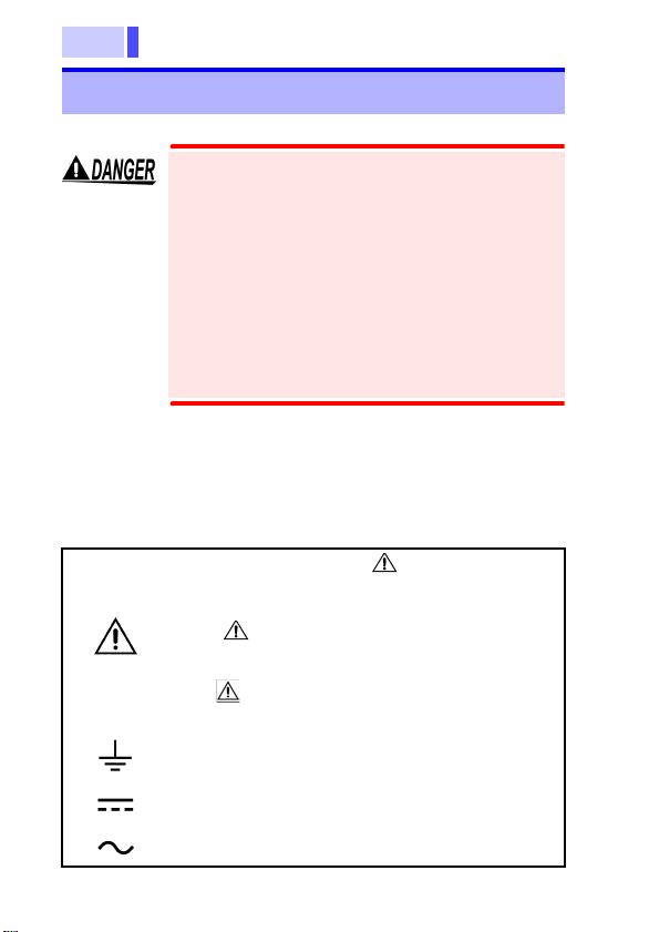
This instrument complies with CAT III safety requirements.
To ensure safe operation of measurement instruments, IEC
61010 establishes safety standards for various electrical
environments, categorized as CAT I to CAT IV, and called
measurement categories. These are defined as follows.
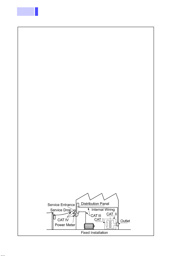
CAT I Secondary electrical circuits connected to an AC
electrical outlet through a transformer or similar
instrument.
CAT II Primary electrical circuits in equipment connected to
an AC electrical outlet by a power cord (portable
tools, household appliances, etc.)
CAT III Primary electrical circuits of heavy equipment (fixed
installations) connected directly to the distribution
panel, and feeders from the distribution panel to
outlets.
CAT IV The circuit from the service drop to the service
entrance, and to the power meter and primary
overcurrent protection instrument (distribution panel).
Higher-numbered categories correspond to electrical
environments with greater momentary energy. So a
measurement instrument designed for CAT III environments
can endure greater momentary energy than a instrument
designed for CAT II.
Using a measurement instrument in an environment
designated with a higher-numbered category than that for
which the instrument is rated could result in a severe accident,
and must be carefully avoided.
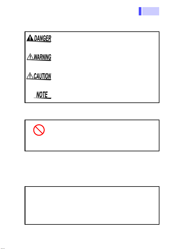
Never use a CAT I measuring instrument in CAT II, III, or IV
environments.
The measurement categories comply with the Overvoltage
Categories of the IEC60664 Standards.
Measurement categories (Overvoltage categories)

5
Notes on Use
Follow these precautions to ensure safe operation
and to obtain the full benefits of the various func-
tions.
Notes on Use
• The maximum input voltage is as follows.
U INPUT: 300 Vrms, 424.3 V peak
ALARM : 30 VDC
CLAMP SENSOR INPUT
: 1.5 Vrms, 2.2 V
peak
Attempting to measure voltage in excess
of the maximum input could destroy the
instrument and result in personal injury or
death.
• The maximum rated voltage between input
terminals and ground is 300 Vrms.
Attempting to measure voltages exceeding
300 Vrms with respect to ground could
damage the instrument and result in
personal injury.
Do not allow the instrument to get wet, and do
not take measurements with wet hands.
This may cause an electric shock.
Do not use the instrument where it may be
exposed to corrosive or combustible gases.
The instrument may be damaged or cause an
explosion.
the instrument
to get wet.
Do not allow
Corrosive or
combustible
gases

Notes on Use
6
Do not use the instrument near a source of
strong electromagnetic radiation, or near a
highly electrically charged object.
These may cause a malfunction.
Operation and Installation environment.
This instrument should be installed and operated
indoors only, between 0 and 50°C (32 to 122°F)
and 80% RH or less.
This instrument is not designed to be entirely
water- or dust-proof.
Do not use it in an especially dusty environment,
nor where it might be splashed with liquid. This
may cause damage.
When the module is used in a dusty environment,
place it in a dustproof case and take measures to
ensure heat dissipation.
Do not store or use the instrument where it
could be exposed to direct sunlight, high tem-
perature or humidity, or condensation.
Under such conditions, the instrument may be
damaged and insulation may deteriorate so that it
no longer meets specifications.
To avoid damage to the instrument, protect it
from physical shock when transporting and
handling.
Be especially careful to avoid physical shock from
dropping.
Do not obstruct the ventilation holes.
Ventilation holes for heat radiation are provided on
the top and rear panels of the instrument. Leave
sufficient space around the ventilation holes and
install the instrument with the holes unobstructed.
Installation of the instrument with the ventilation
holes obstructed may cause a malfunction or fire.
Direct sunlight
Dust
T
emperature o
r
humidity
Electromagnetic
radiation or
highly
charged object
electrically

7
Notes on Use
Wiring
When using the instrument in the case, drill
ventilation holes.
Drill ventilation holes or install a ventilation fan to
prevent heat buildup.
• When the clamp sensor is opened, do not
allow the metal part of the clamp to touch
any exposed metal, or to short between
two lines, and do not use over bare
conductors.
• U INPUT terminals 1 to 3 share the N
terminal and inputs to the terminals are not
insulated from each other. Beware of
electric shock and short-circuiting.
• The CLAMP SENSOR INPUT terminals
are not insulated from the U INPUT
terminals. Beware of electric shock and
short- circuiting.
• A qualified electrician shall perform the
wiring to prevent electric shock.
• Avoid live-line electrical work to prevent
electric shock, module malfunction due to
short-circuiting or opening of the CT
secondary side, overheating, and fire.
• When tightening the screws, confirm that
all screws are securely tightened. A loose
screw may result in module errors or the
generation of high voltage on the CT
secondary side, which may cause fire or
electric shock.

Notes on Use
8
• Be sure to tighten the screws within the
specified torque. Excessive torque may
damage the terminals. Inadequate torque
may result in module errors or the
generation of high voltage on the CT
secondary side, which may cause fire or
electric shock.
• Ensure that the power supply module and
input are OFF until all wiring work is
finished. This will prevent module trouble
and electric shock.
• Ensure that the power supply module and
input are OFF when connecting or
disconnecting the module to the system.
This will prevent electric shock, errors, and
malfunction.
• Avoid using an unused terminal for
relaying or any other purpose to prevent
electric shock, errors, and malfunction.
• Connect the module to a power source that
matches the rating in order to prevent fire.
• Ensure that the power supply, input, and output
are correctly wired according to the wiring dia-
gram. (See Chapter 3 "Preparations " (p.25))
This will prevent fire, malfunction, and errors.
• Use cables of the proper sizes for the rated cur-
rent. This will prevent module errors due to bro-
ken wire, malfunction due to opening of the CT
secondary side, overheating, and fire.
• Use crimp connectors of the proper sizes for the
cables. This will prevent module errors due to
broken wire, malfunction due to opening of the
CT secondary side, overheating, and fire.

9
Notes on Use
• Do not connect a current sensor other than the
specified clamp sensor directly to this module.
Excessive input may result in module malfunc-
tion.
• Be careful to avoid dropping the clamps or other-
wise subjecting them to mechanical shock, which
could damage the mating surfaces of the core
and adversely affect measurement.
• Measurements are degraded by dirt on the mat-
ing surfaces of the clamp-on sensor, so keep the
surfaces clean by gently wiping with a soft cloth.
• If power supply noise poses a problem, use of a
noise filter is recommended.
• Avoid stepping on or pinching cables, which
could damage the cable insulation.
• Keep the cables well away from heat sources, as
bare conductors could be exposed if the insula-
tion melts.
• When the power and signal lines may be subject
to a lightning-induced surge, install a lightning
arrester between another instrument or module
connected to this module and line to protect the
system.

Notes on Use
10
When using Model 9765
Preliminary Checks
• Before using the instrument the first time, verify
that it operates normally to ensure that the no
damage occurred during storage or shipping. If
you find any damage, contact your dealer or
Hioki representative.
• Before using the instrument, make sure that the
insulation on the cables is undamaged and that
no bare conductors are improperly exposed.
Using the product in such conditions could cause
an electric shock, so contact your dealer or Hioki
representative for repair.
• To avoid short circuits and potentially life-
threatening hazards, never attach the
product to a circuit that operates at more
than 30 VAC, or over bare conductors.
• This product should only be connected to
the secondary side of a breaker, so the
breaker can prevent an accident if a short
circuit occurs. Connections should never
be made to the primary side of a breaker,
because unrestricted current flow could
cause a serious accident if a short circuit
occurs.

11
1.1 Product Overview
• The 2331-20 is a measurement module of the Hioki
"Smart Site" (remote measurement system).
• This module measures and records power at
regular intervals.
• And the voltage, current, active power, power
factor, active energy within an interval, and
frequency are also can be measured.
• The 2331-20 is used with the power supply
module, communications module, and module
base.
Overview Chapter 1
1.1 Product Overview
Number of
measurement
circuits
(1P2W/1P3W/3P3W/3P4W)
1 circuit
Voltage input 100 V (70 to 130 VAC)/
200 V (140 to 260 VAC) line
Current Input Clamp sensor
(Conceptual image)
Do not use this module as a wattmeter or watt-
hour meter for business transactions.

1.2 Major Features
12
This is a clamp-type wattmeter is used for a 100/
200 VAC single-phase line to a 3-phase, 4-wire
line.
The recording interval is selectable from 1 second
to 60 minutes.
The maximum, minimum, and average measure-
ments during the recording interval can be
recorded (with sampling once a second).
The module has an alarm output terminal.
1.2 Major Features

13
1.2 Major Features
Rough Estimate of Storable Data Quantity and Time
Action at memory full: Continue recording (Endless)
1P2W
Recording Mode
Instantaneous
Value MAX/MIN/AVE
Instantaneous
Value +
MAX/MIN/AVE
Quantity of
storable data 13000 5900 4600
Recording interval
1 sec. 3.5 hours 1.5 hours 1 hour
2 sec. 7 hours 3 hours 2.5 hours
5 sec. 18 hours 8 hours 6 hours
10 sec. 1.5 days 16 hours 12.5 hours
15 sec. 2 days 1 day 19 hours
20 sec. 3 days 1 day 1 day
30 sec. 4.5 days 2 days 1.5 days
1 min. 9 days 4 days 3 days
2 min. 18 days 8 days 6 days
5 min. 46 days 20 days 16 days
10 min. 92 days 41 days 32 days
15 min. 138 days 61 days 48 days
20 min. 184 days 82 days 64 days
30 min. 277 days 123 days 96 days
60 min. 554 days 246 days 192 days
When the alarm log is ON, the higher the number
of alarms generated, the smaller the recording
period. (Approx. 1/2 of the data per alarm)

1.2 Major Features
14
Action at memory full: Continue recording (Endless)
1P3W/3P3W
Recording Mode
Instantaneous
Value MAX/MIN/AVE
Instantaneous
Value +
MAX/MIN/AVE
Quantity of
storable data 10000 4400 3400
Recording interval
1 sec. 2.5 hours 1 hour 0.5 hours
2 sec. 5.5 hours 2 hours 1.5 hours
5 sec. 14.5 hours 6 hours 4.5 hours
10 sec. 1 day 12 hours 9.5 hours
15 sec. 1.5 days 18 hours 14 hours
20 sec. 2 days 1 day 19 hours
30 sec. 3.5 days 1.5 days 1 day
1 min. 7 days 3 days 2 days
2 min. 14 days 6 days 4.5 days
5 min. 36 days 15 days 11 days
10 min. 73 days 30 days 23 days
15 min. 110 days 46 days 35 days
20 min. 147 days 61 days 47 days
30 min. 221 days 92 days 71 days
60 min. 443 days 184 days 143 days
When the alarm log is ON, the higher the number
of alarms generated, the smaller the recording
period. (Approx. 1/2 of the data per alarm)

15
1.2 Major Features
Action at memory full: Continue recording (Endless)
3P4W
Recording Mode
Instantaneous
Value MAX/MIN/AVE
Instantaneous
Value +
MAX/MIN/AVE
Quantity of
storable data 8800 3500 2700
Recording interval
1 sec. 2 hours 0.5 hours 0.5 hours
2 sec. 4.5 hours 1.5 hours 1.5 hours
5 sec. 12 hours 4.5 hours 3.5 hours
10 sec. 1 day 9.5 hours 7.5 hours
15 sec. 1.5 days 14.5 hours 11 hours
20 sec. 2 days 19.5 hours 15 hours
30 sec. 3 days 1.5 days 22.5 hours
1 min. 6 days 2 days 1.5 days
2 min. 12 days 4 days 3.5 days
5 min. 30 days 12 days 9 days
10 min. 61 days 24 days 18 days
15 min. 92 days 36 days 28 days
20 min. 123 days 49 days 37 days
30 min. 184 days 73 days 56 days
60 min. 369 days 147 days 113 days
When the alarm log is ON, the higher the number
of alarms generated, the smaller the recording
period. (Approx. 1/2 of the data per alarm)

1.2 Major Features
16
Action at memory full: Stop recording (Memory full stop)
1P2W
Recording Mode
Instantaneous
Value MAX/MIN/AVE
Instantaneous
Value +
MAX/MIN/AVE
Quantity of
storable data 15000 6800 5300
Recording interval
1 sec. 4 hours 1.5 hours 1 hour
2 sec. 8.5 hours 3.5 hours 1.5 hours
5 sec. 21 hours 9 hours 7 hours
10 sec. 1.5 days 18.5 hours 14.5 hours
15 sec. 2.5 days 1 day 22 hours
20 sec. 3.5 days 1.5 days 1 day
30 sec. 5 days 2 days 1.5 days
1 min. 10 days 4.5 days 3.5 days
2 min. 21 days 9 days 7 days
5 min. 53 days 23 days 18 days
10 min. 106 days 47 days 37 days
15 min. 159 days 71 days 55 days
20 min. 213 days 94 days 74 days
30 min. 319 days 142 days 111 days
60 min. 639 days 284 days 222 days
When the alarm log is ON, the higher the number
of alarms generated, the smaller the recording
period. (Approx. 1/2 of the data per alarm)
Table of contents
Other Hioki Measuring Instrument manuals

Hioki
Hioki MEMORY HiCORDER MR8847-01 User manual

Hioki
Hioki CM4375 User manual

Hioki
Hioki 3490 User manual

Hioki
Hioki LCR HiTESTER 3535 Instruction manual

Hioki
Hioki CM3286 User manual

Hioki
Hioki 3287 User manual

Hioki
Hioki 3532-50 User manual

Hioki
Hioki MR8875 User manual

Hioki
Hioki MR8847-51 User manual

Hioki
Hioki 3506-10 Parts list manual
Popular Measuring Instrument manuals by other brands

Bartec
Bartec VOLUTANK Petro 3003 quick guide

Seca
Seca 287 Instruction manual and guarantee

Xylem
Xylem wtw pHotoFlex pH quick start guide

GE
GE JXSOUSV1 owner's manual

EUTECH INSTRUMENTS
EUTECH INSTRUMENTS STANDARD PHSCAN 2 PH TESTER Caractéristiques

Endress+Hauser
Endress+Hauser Liquiline System CA80AM Brief operating instructions