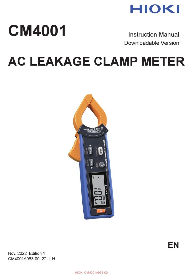
Hioki 3283-20 User manual

EN
3283-20
CLAMP ON LEAK HiTESTER
Instruction Manual
June 2015 Edition 1
3283C981-00 15-06H


i
Contents
Introduction.........................................................................1
Checking Package Contents.............................................1
Safety Information..............................................................2
Operating Precautions.......................................................7
1 Overview 11
1.1 Overview and Features.................................11
1.2 Parts and Functions......................................13
1.3 Liquid Crystal Display ..................................15
2 Pre-measurement Preparation 19
2.1 Flow of Measurement ...................................19
2.2 Installing/Replacing the Battery ..................20
2.3 Inspection Prior to Use.................................23
2.4 Attaching the Hand Strap.............................24
3 Performing Measurements 25
3.1 Measuring Leakage Current.........................25
Locating an insulation failure....................................28
Selecting the measurement range............................29
Setting a slower display update rate (SLOW)...........30
Setting a faster display update rate (FAST)..............30
Measuring an intensely uctuating load current .......31
Obtaining bar graph displays (BAR GRAPH) ...........32
Displaying the frequency (Hz)...................................33
Measuring load current.............................................34
3.2 Reducing Noise
(Filter Function – FILTER).............................35
3.3 Hold Data (Data Hold Function – HOLD).....36
3283C981-00

ii
Contents
3.4 Checking Maximum, Minimum and
Average Values
(Recording Function –
REC)...................................................................37
Bar graph displays (BAR GRAPH) ...........................39
3.5 Limiting Battery's Power Consumption
(Auto power-off function – APS)..................41
3.6 Disabling the Buzzer.....................................42
4 Specications 43
4.1 MeasurementSpecications........................43
AC current: Amperes rms (display of true rms).........44
Frequency Hz ..........................................................45
4.2 GeneralSpecications .................................45
5 Maintenance and Servicing 49
5.1 Repair, Inspection and Cleaning..................49
5.2 Troubleshooting............................................51
5.3 Error Displays................................................52
5.4 Message Displays .........................................52

1
Introduction
Introduction
Thank you for choosing the Hioki 3283-20 Clamp On Leak HiTester.
To ensure that your instrument performs as designed over the long
term, please handle this instruction manual carefully and keep it
handy for future reference.
Checking Package Contents
Once you have received the instrument, verify that it has not suffered
any damage during shipment before using it. If you discover any
damage or nd that the instrument does not operate as stipulated in
its specications, please contact your authorized Hioki distributor or
reseller.
Verify that the packaging includes all contents.
3283-20 9399 Carrying Case Hand Strap
6LR61 Alkaline Battery
× 1 Instruction Manual

2
Safety Information
Safety Information
The 3283-20 has been designed and tested in accordance with the
IEC 61010 safety standard and shipped in a safe state. However,
failure to adhere to the precautionary information and follow the
instructions provided in this manual may render safety-related
functionality provided by the instrument inoperable.
Before using the instrument, be sure to carefully read the following
safety information.
DANGER
Improper use of the instrument may result in bodily
injury or equipment damage. Read this instruction
manual carefully and ensure that you understand its
contents before operating the instrument.
WARNING
Electricity poses a number of hazards, including electric
shock, overheating, fire, and arc discharge (caused
by a short). Individuals using an electrical measuring
instrument for the first time should be supervised
by a technician who has experience in electrical
measurement.
Protective gear
WARNING
To avoid electric shock when measuring live lines,
wear appropriate protective insulation gear and
adhere to applicable laws and regulations.

3
Safety Information
Safety-related notations
This manual classifies safety information on the basis of the
severity of the associated risk and hazard level using the following
categories.
DANGER Indicates an imminent hazard that could lead to serious
injury or death.
WARNING Indicates a hazard that could lead to serious injury or
death.
CAUTION Indicates a hazard that could lead to minor injury or
that could be expected to result in equipment or other
damage.
IMPORTANT Indicates information or content that is especially
important to keep in mind when operating the instrument
or performing maintenance work.
Indicates a high-voltage hazard.
Warns that failure to verify safety or improper use of the
instrument could lead to electric shock, burns, or death.
Indicates an action that you must refrain from performing.
Indicates an action that you must perform.
*Indicates that there is additional information below.

4
Safety Information
Symbols displayed on the instrument
Indicates the need for caution or a hazard.
When this symbol is displayed on the instrument, refer to the
corresponding section of the instruction manual.
Indicates AC (Alternating Current).
Indicates DC (Direct Current).
Indicates that the instrument may be connected to or
disconnected
from a live circuit.
Indicates a double/reinforced-insulated device.
Symbols related to standards
Indicates the Waste Electrical and Electronic Equipment
Directive (WEEE Directive) in EU member states.
Indicates that the product conforms to regulations set out by the
EC Directive.
Screen display
This instrument uses the following screen displays.
1 2 3 4 5 6 7 8 9 0
A B C D E F G H I J K L M N O P Q R S T U V W X Y Z

5
Safety Information
A different display is used in the case below.
Over-range indication (p. 17).
Other notations
HOLD
(Bold)Bold text is used to indicate language used on keys and other
controls.
[ ]Language from the screen is enclosed in brackets ([ ]).
Accuracy
We dene measurement tolerances in terms of rdg. (reading) and
dgt. (digit) values, with the following meanings:
rdg.(Reading or displayed value)
The value currently being measured and indicated on the
measuring instrument.
dgt.
(Resolution)
The smallest displayable unit on a digital measuring instrument,
i.e., the input value that causes the digital display to show a “1”
as the least-signicant digit.

6
Safety Information
Measurement categories
To ensure safe operation of measurement instruments, IEC 61010
establishes safety standards for various electrical environments,
categorized as CAT II to CAT IV, and called measurement
categories.
DANGER
•Never use a measuring instrument whose measurement
category is lower than the location in which it will be
used. Doing so may result in a serious accident.
•Never use a measuring instrument with no category
labeling in a CAT II to CAT IV measurement category.
Doing so may result in a serious accident.
The 3283-20 conforms to the safety requirements for CAT III (300 V)
measuring instruments.
CATⅡ:
When directly measuring the electrical outlet receptacles
of the primary electrical circuits in equipment connected
to an AC electrical outlet by a power cord (portable tools,
household appliances, etc.)
CAT Ⅲ:
When measuirng the primary electrical circuits of heavy
eqiupment (fixed installations) connected directly to the
distribution panel, and feeders from the distribution panel
to outlets
CAT Ⅳ:
When measuring the circuit from the service drop to the
service entrance, and to the power meter and primary
overcurrent protection device (distribution panel)
T Outlet
CAT II
Internal wiring
Distribution panel
Service entrance
Service drop
CAT IV
Power meter
CAT III
Fixed installation

7
Operating Precautions
Please read the following precautions to ensure that you can use
the instrument safely and fully utilize its functionality.
Checking the instrument before use
Verify that the instrument operates normally to ensure that no
damage occurred during storage or shipping. If you find any
damage, contact your authorized Hioki distributor or reseller.
Installation
WARNING
Installing the instrument in inappropriate locations may
cause a malfunction of instrument or may give rise to an
accident. Avoid the following locations.
• Exposed to direct sunlight or high temperature
• Exposed to corrosive or combustible gases
• Exposed to a strong electromagnetic eld or
electrostatic
charge
• Near induction heating systems (such as high-frequency
induction heating systems and IH cooking equipment)
• Susceptible to mechanical vibrations
• Exposed to water, oil, chemicals, or solvents
• Exposed to high humidity or condensation
• Exposed to high quantities of dust particles

8
Operating Precautions
Handling of the instrument
DANGER
•Do not input a voltage or current in excess of the
ratings indicated on instrument labeling or the
measurement range listed in the specifications.
Doing so may cause damage to, or heating of, the
instrument, leading to bodily injury.
•The maximum measurement current varies with the
frequency, and the current that can be measured
continuously is limited. Operating the instrument at
less than this limitation is referred to as derating.
Do not measure currents in excess of the derating
curve. Doing so may result in instrument damage or
malfunction, re, or burns due to sensor heating.
•To avoid short circuits and potentially life-
threatening hazards, never attach the clamp to a
circuit that operates at more than 300 V AC rms.
•Be sure to connect the instrument to the secondary
side of circuit breakers. In the event of a short, this
side of the circuit breaker will be protected from any
short-circuit current by the breaker. The primary
side of circuit breakers is characterized by high
current capacity, and any short-circuit could result
in damage to the instrument or other equipment.
WARNING
To avoid electric shock, do not approach high-voltage
equipment or wiring when taking measurements
using a transformer's ground wire. If measurement
is difficult because the ground wire is located close
to an exposed high-voltage conductor, reroute the
ground wire before measurement.

9
Operating Precautions
CAUTION
• Be careful to avoid dropping the instrument or otherwise
subjecting them to mechanical shock, which could
damage the mating surfaces of the jaw and adversely
affect measurement.
• Do not place foreign objects between the mating faces of
the jaw or insert foreign objects into the gaps of the jaw.
Doing so may worsen the performances of the sensor or
interfere with clamping action.
• It may not be possible to accurately measure electrical circuits
that have a superposed DC component.
• The indicator lights up when the remaining battery capacity
is low. In this case, the instrument's accuracy is not guaranteed.
Replace the battery immediately.
Precautions when transporting the instrument
When shipping the instrument, handle it with care so as to avoid
damage due to vibration or mechanical shock.

10
Operating Precautions

11
1Overview
1.1 Overview and Features
The 3283-20 is designed for wide-range measurement of current
in live circuits, from very small leak currents up to load currents of
200 amperes. The jaws are made of material with high magnetic
permeability to minimize adverse effects from external magnetic
elds and error due to the position of the conductor measured,
thus raising accuracy.
High-sensitivity ranges with 10 mA full scale
Accurate measurement even of minute leak currents (resolution
10 μA).
Extensive measurement range
Five ranges in a 10 mA to 200 A full scale, for measurement over
an extensive range.
Built-in microcomputers give multifunctionality
SLOW, MAX and MIN are just some of the functions offered by
this compact, multifunctional instrument.
Displays true RMS values
Packs true-rms conversion circuits for accurate measurements
unaffected by leak current distortion.
Filter functions
The widespread use of switching power supplies and equipment
incorporating inverter technology can cause high-frequency
1 Overview

12
Overview and Features
components to be superimposed on leak current waveforms.
The lter functions allow measurement of two kinds of leak
current: the kind caused by insulation faults and the kind that
contains high-frequency components.
Minimized effects from external magnetic elds and
conductor position
The jaws are made of material with high magnetic
permeability, allowing precise measurement near to
transformers, electric motors and other sources of magnetic
elds. And error due to conductor cable position is extremely
low, so that even if the instrument is used as a residual
current transformer, the residual current characteristics are
low and measurement accuracy is good.
Low power consumption
Rated power: 100 mVA
Approximately 40 hours of continuous operation on single
layered-type manganese dry cell battery (6F22)

14
Parts and Functions
Control keys
1
23
4
5678
Key Normally
Power turned on while
holding key down
1POWER key Turns the power on/off –
2key Turns the recording
function off (p. 38)
–
3RANGE key Switches the range
(p. 29)
Disables the buzzer
(p. 42)
4HOLD key
Turns the data hold
function on/off (p. 36)
Cancels the auto
power-off (APS)
function (p. 41)
5FILTER key Turns the lter function
on/off (p. 35)
–
6BAR
GRAPH key Switches the bar graph
display (p. 32)
–
7MAX/MIN
key Turns the recording
function on (p. 37)
–
8SLOW/Hz
key
• Setting a slower display
update rate (p. 30)
• Freq. measurement (p. 33)
–

15
Liquid Crystal Display
1.3 Liquid Crystal Display
3
1
4
25
6
7
8
10
9
1AC measurement (p. 25)
2Hold data (p. 36)
3
AUTO
Auto ranging is enabled (p. 29)
SLOW Update display approx. 1 time/3 seconds (p. 30)
REC Recording function is on (p. 37)
MAX Maximum value (p. 37)
MIN Minimum value (p. 37)
AVE Average value
= (maximum value + minimum value)/2
(p. 37)
4FILTER Filter function is enabled (p. 35)
5Auto power-off function is enabled (p. 41)
6Hz Frequency (p. 33)
7RMS True root-mean-square value (p. 26)
8mA Current (A, mA)
9hour 1 hour/segment (bar graph)
min 1 minute/segment (bar graph)
Over-range indication (bar graph)
10 Battery depleted (p. 16)

16
Liquid Crystal Display
Battery remaining power display
When the power is turned on, all the LCD's segments light up.
Then the model name is displayed, and the bar graph shows the
battery power for 1 second.
Bar graph display with fresh
battery
If the battery
remaining power
is zero, will light up and
the buzzer will sound three
beeps.
When is lighted, the
instrument's accuracy cannot
be assured.
Power shut-off
When the battery voltage drops below a
certain level after lights, the power
will be shut off automatically to protect the
internal memory. [bAtt] and [Lo] will be
displayed to indicate this.
When these are displayed and the power
has been shut off, replace the exhausted
battery with a new one.
Table of contents
Other Hioki Measuring Instrument manuals

Hioki
Hioki IM3523 User manual

Hioki
Hioki SM9001 User manual

Hioki
Hioki 8870-20 User manual

Hioki
Hioki PW3335 User manual

Hioki
Hioki PW3390 User manual

Hioki
Hioki LUX HiTESTER 3423 User manual

Hioki
Hioki PW3198 User manual

Hioki
Hioki 9651 User manual

Hioki
Hioki MR8880-20 User manual

Hioki
Hioki IM7580 User manual