Overview
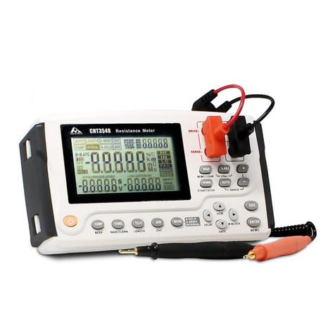
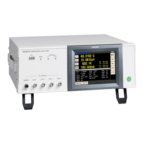
The RM2611 Electrode Resistance Meter is the instrument
component of the RM2610 Electrode Resistance
Measurement System. It is designed to be used with
the RM9003 Press Unit, RM9004 Test Fixture, RM9005
Connection Cable, and RM2612 Resistance Calculation
Software in order to measure potential distribution on
electrode sheets. The RM2611 Electrode Resistance
Meter cannot be used by itself. The instrument’s settings
and operation are controlled by the RM2612 Resistance
Calculation Software. (For more information about wiring
and connections, see the RM2610 Electrode Resistance
Measurement System’s instruction manual.)
Specications
General specications
Operating
environment
Indoors, Pollution Degree 2, altitude of up
to 2000 m (6562 ft.)
Operating
temperature and
humidity
0°C to 40°C (32°F to 104°F), 80% RH or
less (no condensation)
Storage temperature
and humidity
0°C to 50°C (32°F to 122°F), 80% RH or
less (no condensation)
Standards Safety EN61010
EMC EN61326 Class A
Power supply Commercial power
Rated supply voltage: 100 V to 240 V
AC (designed to accommodate voltage
uctuations of ±10% relative to the rated
supply voltage)
Rated supply frequency: 50 Hz, 60 Hz
Anticipated transient overvoltage: 2500 V
Maximum rated power: 40 VA (not
including PC power)
Interfaces •USB port (for connecting the instrument
to a PC)
• Test xture connector
•TEMP.SENSOR terminal (for connecting
the instrument to the Z2001 Temperature
Sensor)
Dimensions Approx. 215W × 80H × 306.5D mm
(8.46″W × 3.15″H × 12.07″D)
Mass Approx. 3.4 kg (119.9 oz.)
Product warranty
period
3 years
Fuse F1.6AH 250 V ×1
Accessories •Power cord
•USB cable
•Z2001 Temperature Sensor
•Instruction manual
•Operating Precautions (0990A905)
Options •RM2612 Resistance Calculation
Software
•RM9003 Press Unit
•RM9004 Test Fixture
•RM9005 Connection Cable
Input, output, and measurement specications
Measured
parameters
DC resistance and temperature
Automatic measurement is performed via the
RM2612 Resistance Calculation Software.
Measurement cannot be performed using the
RM2611 Electrode Resistance Meter alone.
Resistance
measurement
signal
Constant current
Resistance
measurement
method
DC 4-terminal method
Resistance
measurement
terminal
Test xture connector
Resistance
measurement
range
Ranges:
1000 mΩ, 10 Ω, 100 Ω, 1000 Ω, 10 kΩ,
100 kΩ, 1000 kΩ, 10 MΩ*
*Potential measurement results obtained
using the 10 MΩrange are merely values
for reference purposes.
(For more information about range
parameters, see the RM2610 Electrode
Resistance Measurement System's
instruction manual.)
Constant current
generation range
1 μA (min.) to 10 mA (max.)
(For more information about range
parameters, see the RM2610 Electrode
Resistance Measurement System's
instruction manual.)
Test xture
connector
D-sub 50-pin receptacle
Temperature
measurement
terminal
TEMP.SENSOR terminal (for connecting
the instrument to the Z2001 Temperature
Sensor)
Accuracy
guarantee
conditions
•Resistance measurement accuracy
is dened when using the test xture
connector.
•Guaranteed accuracy period: 1 year
•Guaranteed accuracy period after
adjustment made by Hioki: 1 year
•Temperature and humidity for guaranteed
accuracy: 23°C ±5°C (73°F ±9°F),
80% RH or less
•Warm-up time: 60 min. or greater
• Power supply frequency: 50 Hz ±2 Hz,
60 Hz ±2 Hz
(For more information about accuracy
specications, see the RM2610 Electrode
Resistance Measurement System's
instruction manual.)
Interface specications
USB USB 2.0 (Full Speed) Connector:
Series B receptacle
Exclusively for connecting the RM2611
Electrode Resistance Meter to a PC
For dimensional drawings, see the RM2610 Electrode Resistance
Measurement System's instruction manual.
3 4
