Hioki HiTESTER 3540 User manual

INSTRUCTION MANUAL
For...は専用機種。複数の場合は「/」で区切る。
不要の場合はとる。
形名を入力。 複数の場合は「/」で区切る。
3540
品名を入力。
mΩHiTESTER


Contents
Introduction i
Inspection i
Safety ii
Precautions v
Chapter 1 Outline 1
1.1 Four-terminal Method 1
1.2 Temperature Correction Function 3
1.3 Effects of Thermoelectromotive Force 5
Chapter 2 Name and Functions 7
2.1 Front Panel 7
2.2 Rear Panel 11
2.2.1 3540 11
2.2.2 3540-01 11
2.2.3 3540-02 11
2.2.4 3540-03 12
2.3 Top Case 13
Chapter 3 Specifications 15
3.1 General Specifications 15
3.2 Measurement Range 18
Chapter 4 Operating Procedure 21
4.1 Preparing Measurement 21
4.1.1 Measurement Leads 22
4.1.2 About the Temperature Probe 23
4.1.3 Instrument Handle 23
4.2 Resistance Measurement 24
4.2.1 Setting the Power Supply Frequency 25
4.2.2 Changing the Measurement Range 26
4.2.3 Zero Adjust Function 27

4.2.4 Switching the Sampling Speed 28
4.2.5 Hold Function 28
4.2.6 Overload Indicator 29
4.2.7 Current Abnormality (CCERR) Detection
Function 29
4.3 Comparator Function 30
4.3.1 Using the Comparator 31
4.3.2 Selecting the Comparator Table 31
4.3.3 Selecting the Comparator Mode 31
4.3.4 Selecting the Buzzer Mode 32
4.3.5 Configuring the Comparison Values 33
4.3.6 Outputting Comparator Results 34
4.4 Temperature Correction Function (TC) 35
4.5 Temperature Measurement 36
Chapter 5 External Control Features 37
5.1 Connectors 38
5.1.1 The External Terminal 39
5.1.2 The External Connectors 40
5.2 Connections to Terminals 41
5.2.1 The External Terminal 41
5.2.2 External Connectors 42
5.3 Electrical Specification 43
5.3.1 Power Supply Rating 43
5.3.2 Input/output Ratings 44
5.3.3 Internal Circuit 45
5.4 Using the Signals 46
5.4.1 Measurement Control 47
5.4.2 Outputting Measurement Results 50
Chapter 6 RS-232C Interface 53
6.1 Specifications 53
6.1.1 RS-232C Settings 53
6.1.2 Electrical Characteristics 53
6.1.3 Connector 54
6.1.4 Connection Method 54

6.2 Communication Method 55
6.2.1 Connection to Computer 55
6.2.2 Command Transfer Method 55
6.2.3 Command Format 56
6.2.4 Response Format 57
6.2.5 Delimiter 57
6.3 Command 58
6.3.1 Explanation of Command References 58
6.3.2 Command References 59
6.3.3 Received Data 70
Chapter 7 Printers 73
7.1 Making Connections 73
7.2 Printing 75
Chapter 8 Maintenance and Service 77
8.1 Battery Replacement Procedure 77
8.2 Fuse Replacement Procedure 79
8.3 Troubleshooting 80
8.4 Error Code Table 82
8.5 Service 83
8.6 Cleaning 83


i
___________________________________________________________________
Inspection
___________________________________________________________________
Introduction
Inspection
Thank you for purchasing the HIOKI "3540 mΩHiTESTER." To
obtain maximum performance from the product, please read this
manual first, and keep it handy for future reference.
When you receive the product, inspect it carefully to ensure that
no damage occurred during shipping. In particular, check the
accessories, panel switches, and connectors. If damage is evident,
or if it fails to operate according to the specifications, contact your
dealer or Hioki representative.
Accessories
9287-10 CLIP TYPE LEAD 1
9451 TEMPERATURE PROBE 1
Instruction Manual 1
Four R6P manganese batteries 6
Spare fuse to protect the circuit
(F1.0 AH/250 V) 1
Ferrite Clamp
(for AC adapter and temperature probe) 2
External connector socket (Ver.-01 only) 1

ii
___________________________________________________________________
Safety
___________________________________________________________________
WARNING This product is designed to conform to IEC 61010
Safety Standards, and has been thoroughly tested for
safety prior to shipment. However, mishandling
during use could result in injury or death, as well as
damage to the product. Be certain that you
understand the instructions and precautions in the
manual before use. We disclaim any responsibility for
accidents or injuries not resulting directly from
product defects.
・The symbol printed on the product indicates that the
user should refer to a corresponding topic in the
manual (marked with the symbol) before using the
relevant function.
・In the manual, the symbol indicates particularly
important information that the user should read before
Indicates DC (Direct Current).
Indicates the ON side of the power switch.
Indicates the OFF side of the power switch.
Safety
Safety symbols
This manual contains information and warnings essential for safe
operation of the product and for maintaining it in safe operating
condition. Before using the product, be sure to carefully read the
following safety notes.

iii
___________________________________________________________________
Safety
___________________________________________________________________
WARNING
Indicates that incorrect operation presents a
significant hazard that could result in serious injury or
death to the user.
CAUTION Indicates that incorrect operation presents a
possibility of injury to the user or damage to the
product.
NOTE Advisory items related to performance or correct
operation of the product.
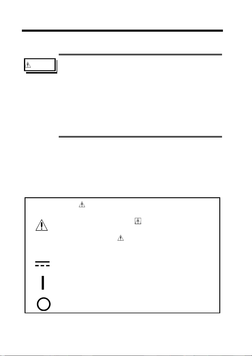
The following symbols in this manual indicate the relative
importance of cautions and warnings.
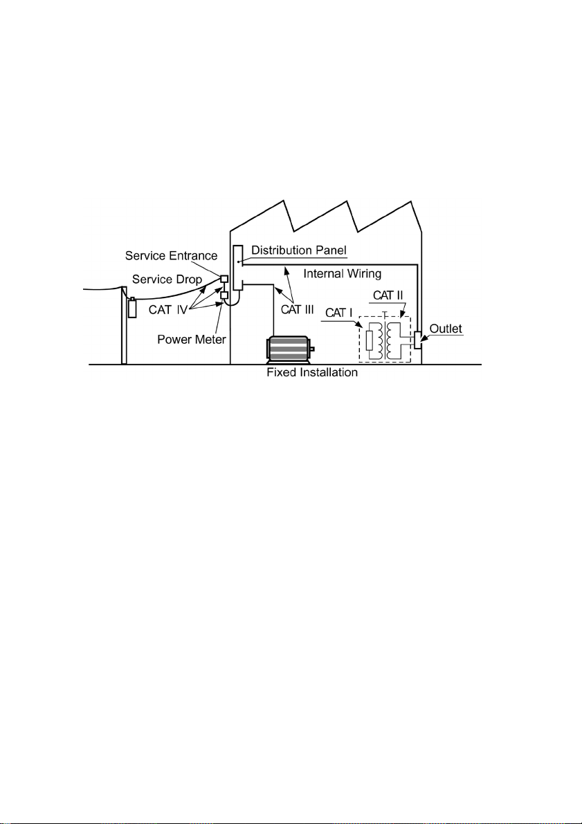
Measurement categories (Overvoltage categories)
To ensure safe operation of measurement instruments, IEC 61010
establishes safety standards for various electrical environments,
categorized as CAT I to CAT IV, and called measurement
categories. These are defined as follows.
CAT I : Secondary electrical circuits connected to an AC
electrical outlet through a transformer or similar device.
CAT II: Primary electrical circuits in equipment connected to an
AC electrical outlet by a power cord (portable tools,
household appliances, etc.)
CAT III: Primary electrical circuits of heavy equipment (fixed
installations) connected directly to the distribution panel,
and feeders from the distribution panel to outlets.
CAT IV: The circuit from the service drop to the service entrance,
and to the power meter and primary overcurrent
protection device (distribution panel).
Higher-numbered categories correspond to electrical environments
with greater momentary energy. So a measurement device designed
for CAT III environments can endure greater momentary energy
than a device designed for CAT II.
Using a measurement instrument in an environment designated
with a higher-numbered category than that for which the

iv
___________________________________________________________________
Safety
___________________________________________________________________
instrument is rated could result in a severe accident, and must be
carefully avoided.
Never use a CAT I measuring product/ instrument in CAT II, III,
or IV environments.
The measurement categories comply with the Overvoltage
Categories of the IEC60664 Standards.

v
___________________________________________________________________
Precautions
___________________________________________________________________
WARNING Use either the specified Hioki model 9445-02/03 AC
ADAPTER (SA10-0910G, SINO-AMERICAN).
CAUTION ・Never apply an external voltage to the SENSE and
SOURCE terminals of the instrument.
・To properly suppress noise, this product must be set to
match the power supply frequency. Before using the
product, make sure the power supply frequency selector
is set correctly, to avoid erroneous readings.
(Refer to 4.2.1 Setting the Power Supply Frequency.)
・Do not store or use the product where it could be
exposed to direct sunlight, high temperature or humidity,
or condensation. Under such conditions, the product
may be damaged and insulation may deteriorate so that
it no longer meets specifications.
・To avoid damage to the product, protect it from
vibration or shock during transport and handling, and be
especially careful to avoid dropping.
・The sensor used in the temperature probe is a thin,
precision platinum film.
Please note that excessive voltage pulses or static
discharges can destroy the film.
To avoid damage or malfunction, avoid hitting the tip of
the temperature probe and overly bending the leads.
When measuring high temperatures, do not let the
handle of the temperature probe or the compensation
lead wire exceed the temperature range.
Precautions
Follow these precautions to ensure safe operation and to obtain the
full benefits of the various functions.

vi
___________________________________________________________________
Precautions
___________________________________________________________________
NOTE The battery indicator appears when battery voltage becomes low.
Replace the batteries as soon as possible.
(Refer to "8.1 Battery Replacement Procedure.")
Be sure to turn the power switch OFF ( ) when not using the
instrument.
Warm up the instrument for at least 30 minutes prior to use, to
attain proper measurement accuracy.
This product should be installed and operated indoors only,
between 0 and 40 and 80 %RH or less.
A fuse is provided in the current source (SOURCE) to protect the
circuit. If the fuse burns out, measurements cannot be made.
Refer to "8.2 Fuse Replacement procedure" on how to check for a
burned-out fuse.
This instrument should not be used with relays or other devices
that handle small signals, since it may damage their contact
coating.
Do not measure points which have a voltage across them. The
main unit of the 3540 will be damaged by an induced voltage if a
measurement is made immediately after a temperature rise test or
dielectric test of a motor or transformer.
Accurate measurement may be difficult to obtain if the instrument
is used near equipment that generates noise.
Also, the indicator may sometimes fluctuate if the device-under-
test picks up noise. Therefore, do not use the instrument in
environments with excessive electrical noise.
The measurement indication may sometimes fluctuate due to
noise pick-up if the temperature probe is touched or held with
bare fingers.
Temperature correction is not possible when the temperature
probe is in contact with the surface of the device to be measured.
Note that the temperature probe is only designed to measure
ambient air temperature.
Significant measurement error will result if the device to be
temperature corrected and the temperature probe are not at the
same ambient air temperature.
Large measurement error will result if the temperature probe is
not inserted fully into the tc sensor jack.

vii
___________________________________________________________________
Precautions
___________________________________________________________________
Make sure the power is turned off before connecting or
disconnecting the AC adapter.
The AC adapter may pick up noise which will affect the
measurement. In such a case, operate the instrument from battery
power.
Measurement range , comparator settings and all settings of the
3540 (except for the measured value) are backed up internally,
but this backup occurs only after a certain amount of time has
elapsed without any operation. Therefore, after changing the
settings, wait a few moments (about 5 seconds) before turning off
the power.
Because the 3540 uses direct current to make measurements,
thermoelectromotive effects can result in measurement errors.
Refer to "1.3 Effects of Thermoelectromotive Force" for details.
When the one that includes the L component such as the
transformer for the power supply a lot is measured a measured
value may not stabilize.

viii
___________________________________________________________________
Precautions
___________________________________________________________________

1
___________________________________________________________________
1.1 Four-terminal Method
___________________________________________________________________
Chapter 1
Outline
1.1 Four-terminal Method
The 3540 mΩHiTESTER is an four-terminal method tester
designed to accurately measure the coil resistance in motors and
transformers, the contact resistance of relays, switches and
connectors, and the trace resistance on printed circuit boards.
In addition, a temperature correction function, comparator function
and data output function are provided, making the 3540 mΩ
HiTESTER ideal for use in production and inspection lines and
systems.
To obtain accurate results when measuring resistance values that
are very small, the Four-terminal method must be used. As shown
in figure 1, in the Two-terminal method, the resistance of the test
leads adds to the resistance of the device being measured, resulting
in an erroneous measurement. However, in the Four-terminal
method shown in the Figure 2, the input consists of two current
terminals to which a constant current is supplied, and two voltage
terminals measured the voltage drop. The voltmeter has a high
input impedance so that essentially no current flows through the
leads connected between the device-under-test and the voltage
terminals. As a result, there is almost no voltage drop across the
resistances r3and r4. Thus the voltage drop due to the lead
resistances and contact resistances is very small, and these can be
canceled out.

2
___________________________________________________________________
1.1 Four-terminal Method
___________________________________________________________________
Ohmmete
r
E
I
r2r1
Ohmmete
r
E
I
Resistance R0
r3
E0
r1
r4
r2
The current Iflows to the measured
resistance R0and the wiring
resistance r1and r2.
Therefore, the measuring voltage E
can be obtained by E = I (r1+R
0+r
2),
and it would include the wiring
resistance r1and r2.
All of the current Iflows to the
measured resistance R0.
Therefore, the voltage drop of r3and
r4become 0, and voltage E and the
voltage drop E0of each end of the
measured resistance R0become
equal. Accordingly, the resistance
measurement without influence of r1
to r4becomes possible.
Resistance R0
Constant current
source
Constant current
source
Voltmeter Voltmeter
Figure 1
Measurement Using the 2-terminal
Method
Figure 2
Measurement Using the 4-terminal
Method

3
___________________________________________________________________
1.2 Temperature Correction Function
___________________________________________________________________
Diameter (mm) Soft copper Tin-plated
soft copper Hard copper
0.10 to 0.26 0.98 0.93 ---
0.26 to 0.50 0.993 0.94 0.96
0.50 to 2.00 1.00 0.96 0.96
2.00 to 8.00 1.00 0.97 0.97
Table 1 Conductivityσ
1.2 Temperature Correction Function
The temperature sensor used in the 3540's temperature probe is a
thin platinum film whose resistance changes according to
temperature. The resistance of the film is detected and converted to
a temperature value by the CPU.
This section explains use of the 3540's temperature coefficient
correction function.
Since the resistance of copper wire is relatively susceptible to
changes in temperature, that fact must be kept in mind when
measuring its resistance. Using the temperature probe, the
resistance value of copper wire can easily be converted to its 20
equivalent for display.
In general, the relationship between the resistance of copper wire
and temperature is as indicated by the following expression.
Rt=R
t0x{1 + αt0 x(t - t0)} (1)
Here, αt0 is referred to as the temperature coefficient, which is
expressed as follows.
αt0 = 1 / [{1 / (0.00393 xα}+(t
0-20)] (2)
Here, σis the conductivity of copper wire. From expressions (1)
and (2), the temperature coefficients of various types of wire with
various conductivities can be calculated, and their resistance values
at a particular temperature obtained. Table 1 shows the
conductivity of various types of copper wire.

4
___________________________________________________________________
1.2 Temperature Correction Function
___________________________________________________________________
For 3540 temperature correction, conductivity σis calculated as
1. Accordingly, when the resistance value R20 that is displayed at
the time of temperature correction is taken as Rt, the measured
resistance at the current ambient temperature is expressed by the
following expression. (Temperature coefficient: α20 = 3930 ppm,
ppm = x10-6)
R20 =R
t/{1+α20 x(t - 20)} (3)
Error occurs during temperature correction because the temperature
coefficient calculated according to expression (2) differs when the
conductivity σis other than 1.
For example, when the tin-plated soft copper wire (diameter 0.10
to 0.26) of Table 1 is measured, σ=0.93givesαt0 of 3650 ppm,
so that the 3540 temperature value contains error.

5
___________________________________________________________________
1.3 Effects of Thermoelectromotive Force
___________________________________________________________________
3540
Metal A Thermoelectromotive force Metal:B
1.3 Effects of Thermoelectromotive Force
Thermoelectromotive force is the potential difference at the
junction of two dissimilar metals. If this emf is large, measurement
errors can result. As the 3540 uses constant direct current flowing
through the object being measured, readings can be affected by
even slight thermoelectromotive force.
Furthermore, the quantity of thermoelectromotive force is
dependent upon the temperature of the measurement environment,
with the force generally being greater at higher temperature.
Thermoelectromotive force occurs at the junction of dissimilar
metals and between the probes of the 3540 and the contacts on the
object being measured. The following figure illustrates
thermoelectromotive force. The battery symbols represent a
junction of dissimilar metals, and the probe symbols represent the
thermoelectromotive force.
As an example of the error effects of thermoelectromotive force, if
the force is 10 µV and the measured resistance is 3 Ω, the current
is 1 mA in the 3 Ωrange, so the measured value displayed on the
3540 is actually
(3 Ωx1mA+10µV) / 1 mA = 3.010 Ω. In this situation,
changing the probe direction to HI-LO leaves the polarity of the
thermoelectromotive force unaffected, so the measured value is
now (3 Ωx1mA-10µV) / 1 mA = 2.990 Ω.

6
___________________________________________________________________
1.3 Effects of Thermoelectromotive Force
___________________________________________________________________
If the measurement error is large due to the effect of
thermoelectromotive force, the following countermeasures can be
employed.
(1) Reverse the probes and use the average measured value.
(2) As the thermoelectromotive force is temperature dependent,
maintain a constant temperature in the measurement environment.
Table of contents
Other Hioki Test Equipment manuals

Hioki
Hioki SM7810 User manual

Hioki
Hioki MEMORY HiCORDER 8855 User manual

Hioki
Hioki 3522-50 User manual

Hioki
Hioki CLAMP ON LEAK HiTESTER 3283 User manual

Hioki
Hioki 3665-20 User manual

Hioki
Hioki 3805-50 User manual

Hioki
Hioki 3174 User manual

Hioki
Hioki FT6031-03 User manual

Hioki
Hioki 3560 User manual

Hioki
Hioki BT3554 User manual

Hioki
Hioki BT3564 User manual

Hioki
Hioki BT3554 User manual

Hioki
Hioki 7011 User manual

Hioki
Hioki 9261 User manual

Hioki
Hioki 8860-50 User manual

Hioki
Hioki BT5525 Instructions for use

Hioki
Hioki CLAMP ON LEAK HiTESTER 3283 User manual

Hioki
Hioki RM3543 User manual

Hioki
Hioki FT6031-50 User manual

Hioki
Hioki Analog MO HiTESTER Series User manual