Hioki 3169-20 Instruction manual

CLAMP ON POWER
Quick Start Manual
3169-20
July 2014 Revised edition 7 3169A983-07 14-07H
HiTESTER
3169-21


Contents
i
Contents
Introduction ________________________________ 1
Key Names and Functions ____________________2
Screen Configuration ..............................................................3
Common Display .....................................................................4
On-Screen Indicators ..............................................................5
Power Measurement _________________________ 6
Measurement Preparations ....................................................9
Basic Settings ........................................................................15
Connect the Voltage Cords and Clamp Sensors to the line
to be Measured .....................................................................18
Confirm the Range ................................................................20
Checking the Wiring ..............................................................22
Measurement Settings ..........................................................24
Start Measurement ................................................................27
View Measured Value ............................................................28
Stop Measurement ................................................................29
Headers of Output Data ........................................................31

Contents
ii

Introduction 1
1
2
3
4
5
6
7
8
9
10
11
The 3169-20 and the 3169-21 Clamp On Power HiTester is supplied with a
instruction manual in addition to this manual. Please be sure to read both
manuals.
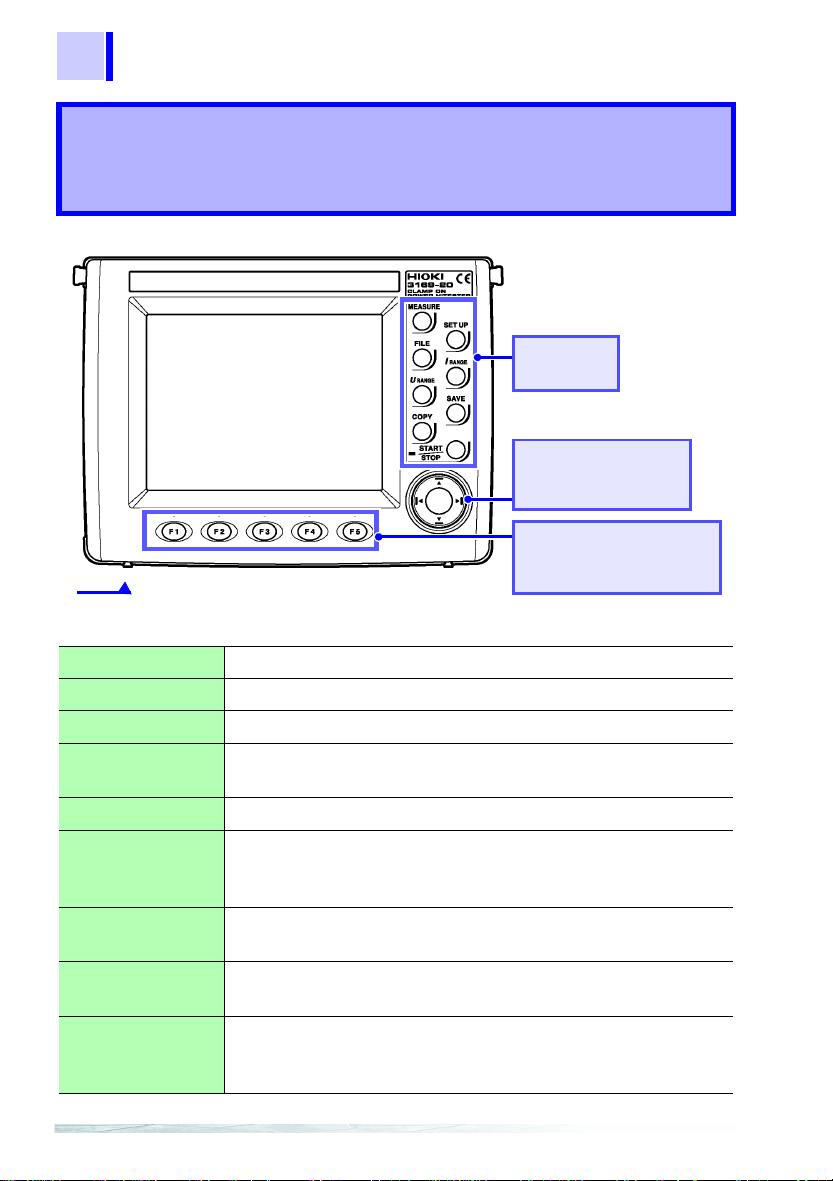
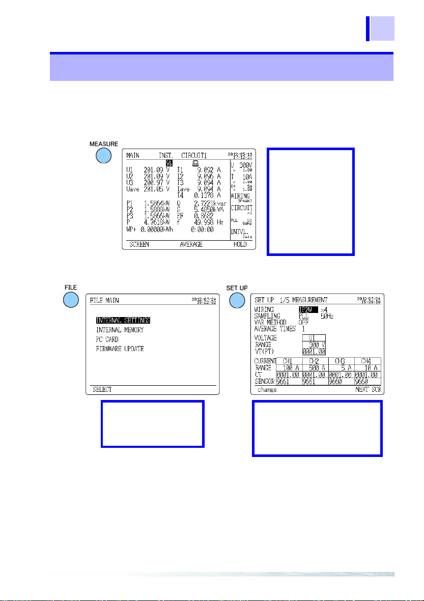
This manual provides a simplified description of the instrument (key names
and functions as well as screens) and measurement process, from the prepa-
ration stage to the completion of measurement, using an example application.
For current input with this instrument, a clamp-on sensor (optional) is
required. For details, refer to the instruction manual for the clamp-on sensor
you are using.
Be sure to review the instruction manual carefully before using the instru-
ment to ensure safe operation.
Model Numbers
In this manual, "3169" is used as the instrument model.
M
Notation
In this manual, the risk seriousness and the hazard levels are classified as
follows.
Introduction
Model No. D/A output function
3169-20 Not available
3169-21 Available
Indicates an imminently hazardous situation that will result in death or
serious injury to the operator.
Indicates a potentially hazardous situation that may result in death or
serious injury to the operator.
Indicates a potentially hazardous situation that may result in minor or
moderate injury to the operator or damage to the instrument or mal-
function.
Indicates prohibited actions.
Indicates the reference.
Indicates a useful measurement tip or fact.
*Additional information is presented below.
See

2Key Names and Functions
Quick Start Manual
Operation Keys
Key Names and Functions
MEASURE key Switches to a screen that displays measurements.
SET UP key Switches to a screen that displays settings or the next screen.
FILE key Used to work on files.
I RANGE key Sets the current measurement range for the circuit to be mea-
sured on-screen.
U RANGE key Sets the voltage measurement range.
SAVE key Enables the manual saving of measurement data on the PC
card or in internal memory. Manual saving is not possible dur-
ing time-series measurement.
COPY key Outputs screen image data to the PC card, internal memory, or
a printer.
START/STOP key Starts or stops time-series measurements including integration
measurement.
START/STOP LED Flashes in green while the instrument is standing by for time-
series measurement, and lights in green while the instrument is
performing time-series measurement.
Instruction manual "Chapter 2 Parts Names"
See
Cursor key
These keys move the
cursor on the screen.
Operation
Keys
Function (F1-F5) keys
Selects or switches the
screens and setting items.

Key Names and Functions 3
1
2
3
4
5
6
7
8
9
10
11
The screens are divided into three basic types: measurement screens, set-
ting screens, and file screens. Each screen is selected using three operation
keys: MEASURE, SET UP, and FILE.
Screen Configuration
Measurement screen
Setting screen
MAIN
POWER
INTEGRATE
DEMAND
ZOOM
HARMONIC LIST
HARMONIC GRAPH
WAVEFORM
WIRING CHECK
WIRING DIAGRAM
MEASUREMENT
DATA OUTPUT
SAVE, PRINT ITEMS
SYSTEM
D/A OUTPUT (3169-21 only)
INTERNAL SETTINGS
INTERNAL MEMORY
PC CARD
FIRMWARE UPDATE
File screen

4Key Names and Functions
Quick Start Manual
This section of the screen shows information common to all measurement
screens (except the zoom screen and the wiring diagram screen).
Common Display
Common Display
Time
Range
Wiring
No. of circuits
Synchronization method
Interval
Time Displays the current time.
Range Displays the voltage range and current range of the on-
screen circuit. The VT(PT) ratio and CT ratio are shown
under these ranges. The current range and CT ratio of I4 are
shown only when 3P4W4I is set as the wiring method.
Wiring Displays the wiring method set on the setting screen.
No. of circuits Displays the number of circuits to be measured as set on the
setting screen.
Synchronization
method Displays the synchronization method and frequency of the
line to be measured as set on the setting screen.
Interval Displays the interval set on the setting screen.

Key Names and Functions 5
1
2
3
4
5
6
7
8
9
10
11
On-Screen Indicators
Goes on when the reactive-power-meter method is ON.
Instruction manual "5.2.3 Setting the Reactive-Power Meter Method"
Goes on when the displayed measurement is held.
Goes on when the medium for saving data is set to PC card.
Flashes when the PC card is accessed.
Goes on when the medium for saving data is set to internal memory.
Flashes when the internal memory is accessed.
Goes on when the PC card or internal memory is full.
Goes on when the device to be connected to the RS-232C is set to PC.
Goes on when the device to be connected to the RS-232C is set to
printer.
Goes on when the PLL is unlocked; the synchronization method is auto-
matically switched over to the fixed clock.
Instruction manual "5.2.2 Setting the Synchronization Method"
Goes on when the keys are locked.
Goes on when the voltage or current dynamic range is exceeded.
Displayed when the range is exceeded.
Reference U3* and I3* indicate that the data is obtained by calculating the
2-voltage, 2-current measurement results when 3P3W2M (three-
phase, 3-wire, 2-power-meter method) is selected.
Instruction manual "Appendix"
See
See
See

6Power Measurement
Quick Start Manual
This chapter explains setting and measurement procedures using the follow-
ing example.
Be sure to read the “Operating Precautions” section of the instruction manual
as well as other precautionary information that can be found its chapters
before using the instrument.
Procedures
See p.8 for more information about what you will need to perform measure-
ment.
* The reactive-power-meter method is used to measurereactive power directly from the
voltage and current, like a reactive power meter installed for large power consumers.
Power Measurement
• Data is automatically output to the PC card at 5-minute intervals.
• Average value (voltage, current, and power) and integrated power are
stored on the PC card.
• The reactive power-meter method*is not used.
Example:
Measure the power of a Three-phase 3-wire 200 V line for 7 days.
1. Connect the power cord. (p.10)
2. Connect the voltage cord to the 3169. (p.11)
3. Connect the clamp sensor to the 3169. (p.12)
4. Insert the PC card. (p.13)
5. Turn the Power switch ON. (p.14)
6. Basic settings (p.15)
7. Connect the voltage cords and clamp sensors to the line to be
measured. (p.18)
8. Confirm the range. (p.20)
9. Checking the wiring. (p.22)
10. Measurement settings (p.24)
11. Start measurement. (p.27)

Power Measurement 7
1
2
3
4
5
6
7
8
9
10
11
System diagram
12. View measured values (p.28)
13. Stop measurement. (p.29)
A
B
C
Black
Red
Yellow
Model 9661 sensor Facethecurrent
flow
direction arrow
toward the Load
L9438-53 Voltage Cord
3P3W
200 V
50 Hz
(500 A rated)
PC card
Measurementdataissavedin
CSV format to the PC card.
50 A load
Input cord label (Red)
Input cord label (Yellow)
2. 2. 2.
3. 3.
5. 4.
1.
(p.9)
(p.9)
8. 9.
Basic Settings
(Measurement Setting
Screen)
Wiring method : 3P3W2M
Number of circuits to be measured
: x 1 (1 circuit)
Sampling : PLL
Frequency : 50 Hz
VAR Method : OFF
Average times : 1
Voltage range : 300 V
Current range : 50 A
Sensor : Model 9661
6.
11.
7.
7.
7.
7.
7.
Measurement Method
Data Output Setting Screen)
Meas. Start : Time (2012/06/20 08:00)
Meas. Stop : Time (2012/06/27 08:00)
Interval time : 5 minutes
Medium for saving data : PC card
Data file name : user specified
Measurement Method
(Save/Print Items Setting Screen)
Normal measurement : ON
Average : ON
Integrated power&demand : ON
10.
LOAD
SOURCE
Upper side of the
3169

8Power Measurement
Quick Start Manual
Instrument and Accessories Required for Measurement
Model 3169 x 1
Power cord x 1
PC card (optional) x 1
Model L9438-53 Voltage Cord x 3 Model 9661 Clamp on Sensor x 2
(optional)
Spiral tubes x 5
(for banding the cords)
Black
Red
Yellow
Input cord label x 1

Power Measurement 9
1
2
3
4
5
6
7
8
9
10
11
1. Wind the spiral tubes around the cords as necessary.
2. Attach the input cord labels as necessary.
Measurement Preparations
Insert the voltage cords
securely into the voltage
clips.
For CH2
For CH1
Red Yellow

10 Power Measurement
Quick Start Manual
3. Connect the power cord.
To avoid electrical accidents and to maintain the safety spec-
ifications of this instrument, connect the power cord pro-
vided only to a 3-contact (two-conductor + ground) outlet.

Power Measurement 11
1
2
3
4
5
6
7
8
9
10
11
4. Connect the Voltage cord to the voltage input terminals of
the 3169.
• Connect the voltage cords to the instrument first, and then
to the active lines to be measured.
Observe the following to avoid electric shock and short cir-
cuits.
• Voltage cord should only be connected to the secondary
side of a breaker, so the breaker can prevent an accident if
a short circuit occurs. Connections should never be made
to the primary side of a breaker, because unrestricted cur-
rent flow could cause a serious accident if a short circuit
occurs.
• Do not allow the voltage cord clips to touch two wires at the
same time.
Never touch the edge of the metal clips.
• Voltage input terminals U1, U2, and U3are common to the N
terminal and are not insulated. To avoid the risk of electric
shock, do not touch the terminals.
• To prevent an electric shock accident, confirm that the
white or red portion (insulation layer) inside the cable of
voltage cord is not exposed. If a color inside the cable is
exposed, do not use the cable.
For safety reasons, when taking measurements, only use the
L9438-53 Voltage Cord provided with the instrument.
Insert plugs all the way in.
Voltage input terminals
NU
1U2
Black Red Yellow

12 Power Measurement
Quick Start Manual
5. Connect the clamp sensor (Model 9661) to the current
input terminals of the 3169.
When disconnecting the BNC connector, be sure to release the
lock before pulling the connector. Forcibly pulling the connector
without releasing the lock, or pulling on the cable, can damage the
connector.
Lock the
connector
Line up
Line up
BNC connector
Current input terminal
1
2
Current input terminals
Red
CH1 Yellow
CH2
Verify that each channel color matches the
color of each input code label.

Power Measurement 13
1
2
3
4
5
6
7
8
9
10
11
6. Insert the PC card into the 3169.
Use only PC Cards sold by Hioki. Compatibility and perfor-
mance are not guaranteed for PC cards made by other manu-
facturers. You may be unable to read from or save data to
such cards.
• Inserting a PC card upside down, backwards or in the wrong
direction may damage the instrument.
• Never eject a PC card while it is being accessed by the instru-
ment. Data on the PC card may be lost.
• Some PC cards are susceptible to static electricity. Exercise
care when using such products because static electricity could
damage the PC card or cause malfunction of the instrument.
• With some PC cards, the instrument may not start up if power is
turned on while the PC card is inserted. In such a case, turn
power on first, and then insert the PC card. It is recommended to
try out operation with a PC card before starting to use it for
actual measurements.
Eject button (pull out a PC card)
PC card slot
The arrow in the direction
of the PC card slot

14 Power Measurement
Quick Start Manual
7. Turn the POWER switch ON.
8. Adjusts the contrast of the screen as necessary.
Before turning the instrument on, make sure the supply volt-
age matches that indicated on it’s power connector. Connec-
tion to an improper supply voltage may damage the product
and present an electrical hazard.
How to set the clock
Instruction manual
"5.5.7 Setting the Clock"
See
Contrast
control knob

Power Measurement 15
1
2
3
4
5
6
7
8
9
10
11
To initialize settings (p.17)
Basic Settings
See
1. Press the key to display the setting screen.
If the following screen is not displayed, press the SET UP key several times.
2. Set all items as shown on the screen below.
Move the cursor to the setting you wish to configure with the key and set it
with the to keys.
Instruction manual
"5.2 Setting on the
Measurement Set-
ting Screen (MEA-
SUREMENT)"
See
1
2
3
4
Two methods for performing 3-phase/3-wire power
measurement
• 3-phase/3-wire/2-meter (3P3W2M) method:
Power is calculated from two sets of voltage and current values (use for
normal measurement).
• 3-phase/3-wire/3-meter (3P3W3M) method:
Power is calculated from three sets of voltage and current values (use
when you wish to verify each phase’s power balance).
1

16 Power Measurement
Quick Start Manual
What is VT ratio?
VT is used in high-voltage measurement to convert (step-down) the voltage
measuredtoasmallerlevel andsupply theconversion resultto aninstrument.
VT ratio (voltage transformation ratio): A ratio used to convert the secondary volt-
age of VT to the primary voltage.
Example
When the primary voltage is 6600 V and the secondary voltage is 110 V, the VT
ratio is 60 (6600 V/110 V). In this case, as the rated measurement voltage is 110
V, set the voltage range to 150 V.
2
Clamp sensor and current range:
Selectable current ranges vary according to the clamp sensor used.
Choose a clamp sensor head as appropriate for the measurement target.
Clamp sensors Range
Model 9660, 9695-03 5 A, 10 A, 50 A, 100 A
Model 9661 5 A, 10 A, 50 A, 100 A, 500 A
Model 9667-5kA (5000 A range) 5 kA
Model 9667-500A (500 A range) 500 A
Model 9669 100 A, 200 A, 1 kA
Model 9694 0.5 A, 1 A, 5 A
Model 9695-02 0.5 A, 1 A, 5 A, 10 A, 50 A
Model number and
the maximum rated
current Reference
When using the CT9667 sensor,
choose “9667” for the sensor on
the Measurement Setting screen.
3
What is CT ratio?
CT is used to measure large current to reduce the current measured to a
smaller level and supply the conversion result to an instrument.
CT ratio (current transformation ratio): A ratio used to convert the second-
ary current of CT to the primary current.
When the primary current is 100 A and the secondary current is 5 A, the
CT ratio is 20 (100A/5 A). In this case, as the rated measurementcurrent
is 5 A, set the current range to 5 A.
4
Other manuals for 3169-20
3
This manual suits for next models
1
Table of contents
Other Hioki Test Equipment manuals