2
The performance features described here
are binding only if they have been expressly
guaranteed in the contract. We have
checked that the contents of the technical
publication agree with the hardware and
software described. However, it is not possi-
ble to rule out deviations completely, so we
are unable to guarantee complete agree-
ment. However, the details in the technical
publication are checked regularly. Any cor-
rections which prove necessary are contai-
ned in subsequent editions. We are grateful
for suggestions for improvement.
We reserve the right to make technical
modifications.
Permission is not given for the circulation
or reproduction of this document, its use or
the passing on of its contents unless gran-
ted expressly. Contravention renders the
perpetrator liable for compensation for
damages. All rights reserved, in particular
in the case of patent grant or registration of
a utility or design.
Copyright
© Hirschmann
Automation and Control GmbH 2007
All Rights Reserved
Safety instructions
Certified usage
Please observe the following:
zWarning
The device may only be employed
for the purposes described in the
catalog and technical description,
and only in conjunction with external
devices and components recommen-
ded or approved by Hirschmann.
The product can only be operated
correctly and safely if it is transpor-
ted, stored, installed and assembled
properly and correctly. Furthermore,
it must be operated and serviced
carefully.
Supply voltage
To be supplied by a NEC Class 2 power
supply via MICE switch module.
For Power over Ethernet modules: Connect
a NEC Class 2 power supply only.
Use 60/75°C or 75°C copper (CU) wire only.
Shielding Ground
Note: The shielding ground of the connec-
table twisted pairs lines is connected to the
front panel as a conductor.
䡺Beware of possible short circuits when
connecting a cable section with conductive
shielding braiding.
Housing
zWarning!
Only technicians authorized by
Hirschmann are permitted to open
the housing.
䡺Make sure that the electrical installation
meets local or nationally applicable safety
regulations.
zWarning!
Never insert pointed objects (thin
screwdrivers, wires, etc.) into the
inside of the subrack! This especial-
ly applies to the area behind the
socket connectors. Failure to ob-
serve this point may result in inju-
ries caused by electric shocks.
General Safety Instructions
䡺Particular attention is to be paid to all
warnings and items of information relating
to safety.
zWarning!
Any work that may have to be per-
formed on the electrical installation
should be performed by fully quali-
fied technicians only.
zWarning!
LED- or LASER components accor-
ding to IEC 60825-1 (2003):
CLASS 1 LASER PRODUCT.
LIGHT EMITTING DIODE - CLASS 1
LED PRODUCT.
sWarning!
(POF media modules ...-P4-...)
LED light
DO NOT STARE INTO THE BEAM OR
VIEW DIRECTLY WITH OPTICAL
INSTRUMENTS (e.g. lens, microsco-
pe). Failure to observe this warning
within a distance of 100 mm can
endanger your eyes. Light is emitted
from the optical connectors or from
the ends of the optical fibers that are
connected to them.
Light Emitting Diode CLASS 2M
Wave length 650 nm
Power <2 mW
According to IEC/CEI 60825-1:2003.
ESD guidelines
The media modules contain components
highly sensitive to electrostatic fields.These
components can be easily destroyed or
have their lives shortened by an electrical
field or by a discharge caused by touching
the contacts.
You can find more informationen about
devices vulnerable to electrostatic fields in
DIN EN 61340-5-1 (2001-08) and
DIN EN 61340-5-2 (2002-01)
,Recycling Note:
After its use, this product has to be
processed as electronic scrap and
disposed of according to the prevai-
ling waste disposal regulations of
your community / district / country /
state.
1. MICE Hardware
1.1 SWITCH BASIC MODULES
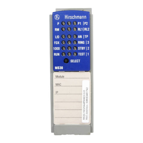
The documentation enclosed to the switch
basic module gives you a detailed descripti-
on of the switch basic modules:
– „User Manual Installation
Industrial ETHERNET Switch MICE
MS20/MS30” for MS20-… and MS30-…
– „User Manual Installation
Industrial ETHERNET Switch Power MICE”
– “Description and Operating Instructions
Industrial ETHERNET Modular Industrial
Communication Equipment MICE/Power
MICE” for
– MS2108-2 (MICE 2000)
– MS3124-4 (MICE 3000)
1.2 MEDIA MODULES
– MICE 2000: See Table 1.
– MICE 3000: See Table 2.
– MICE 4000: See Table 3.
– MICE media modules open variant:
See Table 4.
1.3 MB-2T EXPANSION MODULE
The MB-2T expansion module allows you to
add 2 slots to the MS20-1600, MS30-1602,
MS3124-4, MS4128-5 MICE switch basic
module for installing media modules.
1.4 SFP MODULES
SFP modules are optical transceivers
(Fast ETHERNET and Gigabit ETHERNET
SFP modules see chapter 7 Technical Data).
The SFP modules are plugged into the SFP
slots of the Fast ETHERNET media module
MM3-4SFP (MM20-Z6Z6Z6Z6) or of the
Gigabit ETHERNET media modules
MM4-4TX/SFP / MM4-2TX/SFP to provide a
F/O port.
The MM3-4SFP (MM20-Z6Z6Z6Z6) has four
slots for SFP modules (100 Mbit/s).
The MM4-4TX/SFP / MM4-2TX/SFP has
four/two TP interfaces and four/two slots for
SFP modules (100/1000 Mbit/s). Inserting
the SFP module deactivates the correspon-
ding TP interface.
1.5 MM22-T1T1T1T1
POE MEDIA MODULE
The MM22-T1T1T1T1 PoE media module
(deeper module style) supports Power over
ETHERNET (PoE) in compliance with IEEE
802.3af. It enables the connection and the
remote supply of e.g. IP telephones (voice
over IP), webcams, sensors, print servers
and WLAN access points via 10BASE-
T/100BASE-TX. With PoE, the power supply
of these data terminal equipments is served
via the twisted pair cable.
The MM22-T1T1T1T1 media module offers
four 10BASE-T/100BASE-TX ports (RJ45
connectors) for connecting network seg-
ments or PoE data terminal equipments
(PD, Powered Device) up to class 0 (respec-
tively class 3) maximum.
The current is supplied on the idle wire
pairs (spare pairs); the ports are not electri-
cally isolated against each other.
In compliance with IEEE 802.3af, each port
has the attributes:
– Endpoint PSE
– Alternative B.
2. Functional description
The ports of a MICE represent a terminal
connection for the connected LAN segment.
You can connect single devices or complete
network segments.
2.1 INTERFACES
TP/TX/FL/FX terminal devices or other
TP/TX/FL/FX segments can be connected to
the 10/100/1000 Mbit/s ports of the media
modules.
The MICE and MS20 supports both ETHER-
NET 10 Mbit/s and Fast ETHERNET 100
Mbit/s, the Power MICE and MS30 supports
additionally Gigabit ETHERNET 1000 Mbit/s.
The TP/TX ports support autocrossing,
autonegotiation and autopolarity.
2.2 DIP SWITCH (MM3-AUI)
With the 3-pin DIP switch on the MM3-2AUI
module
– you can switch on or off the SQE test fun-
ction at port 1 with the SQE-Test Port 1
switch.


