HIS HIS-ML17-xxxB Series User manual

Hope Industrial Systems, Inc.
User Manual
17” Panel Mount Industrial Monitor
Revision B
Model Numbers: HIS-ML17- _ _ _ B

2
Table of Contents
SAFETY AND REGULATORY INFORMATION....................................................................3
Warning..............................................................................................................................3
FCC Notice.........................................................................................................................3
CONTROL PANEL BUTTONS AND INDICATORS..............................................................4
OSD FUNCTIONS .................................................................................................................6
Picture ................................................................................................................................6
Color...................................................................................................................................6
Image..................................................................................................................................7
On-Screen Display (OSD) ..................................................................................................8
Setup..................................................................................................................................8
Information..........................................................................................................................8
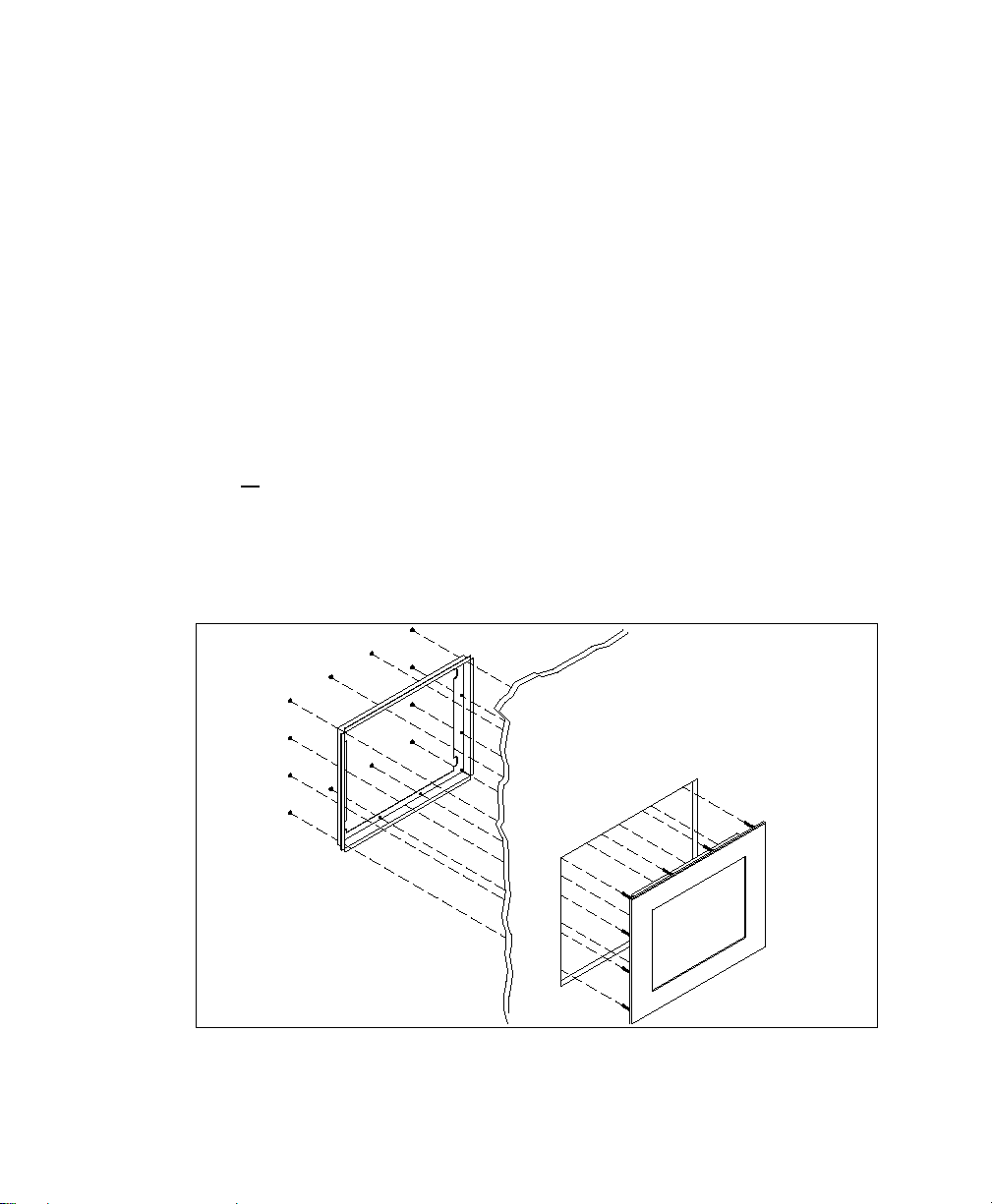
INSTALLATION INSTRUCTIONS.........................................................................................9
Preparing for Installation.....................................................................................................9
Installation into Panel........................................................................................................10
TOUCHSCREEN DRIVER INSTALLATION .......................................................................11
CLEANING...........................................................................................................................12
TROUBLESHOOTING ........................................................................................................13
DRAWINGS .........................................................................................................................15
SPECIFICATIONS...............................................................................................................17
Display..............................................................................................................................17
Video ................................................................................................................................18
Electrical...........................................................................................................................18
Environmental...................................................................................................................18
Functional.........................................................................................................................19
Enclosure..........................................................................................................................19
Physical ............................................................................................................................19
VGA Pin assignment ........................................................................................................20
FACTORY PRESET TIMING...............................................................................................21
WARRANTY STATEMENT .................................................................................................22

3
Safety and Regulatory Information
Warning
To prevent fire or shock hazard, do not expose the unit to rain or moisture. Dange-
rously high voltages are present inside the unit. Do not disassemble the unit. Refer
servicing to qualified personnel only.
This equipment is not intended for use in critical applications where its failure to op-
erate would create immediate life threatening circumstances. Applications including
but no limited to nuclear reactor control, aerospace navigation systems and life
support systems are not appropriate for this product.
This product is intended to be mounted in a suitable cabinet or other enclosure. The
NEMA 4, 4x or 12 ratings are applicable only when properly installed in a like rated
enclosure.
This product is a UL Recognized Component and must be used with a listed com-
puter.
FCC Notice
This equipment has been tested and found to comply with the limits for a Class A digital
device, pursuant to Part 15 of the FCC Rules. These limits are designed to provide rea-
sonable protection against harmful interference when the equipment is operated in a com-
mercial environment. This equipment generates, uses, and can radiate radio frequency
energy and, if not installed and used in accordance with the instruction manual, may cause
harmful interference to radio communications. Operation of this equipment in a residential
area is likely to cause harmful interference in which case the user will be required to correct
the interference at his own expense. Any changes or modifications not expressly approved
by the grantee of this device could void the user’s authority to operate the device.

4
Control Panel Buttons and Indicators
Control Panel Button Mode Description
MENU Always Opens the OSD menu. Also used to exit the OSD
menu or return to the previous menu.
-
When the
OSD Menu is
NOT
Displayed
MagicBright: Provides an optimum viewing envi-
ronment depending on the contents of the image you
are watching. Six different modes are available.
Each mode has its own pre-configured brightness
value:
1) Text: For documentation or work involving
heavy text
2) Internet: For working with a mixture of images
such as text and graphics
3) Entertain: For watching motion pictures such as
a DVD
4) Game:For moving pictures such as a video
game
5) Sport: For moving pictures such as sports
6) Custom: Although the values are carefully cho-
sen by our engineers, the pre-configured values
may not be comfortable to your eyes depending
on your taste. If this is the case, adjust the
Brightness and Contrast using the OSD menu.
Note: Pressing the menu button for more than 5
seconds will lock the OSD function, repeat to unlock.
When the
OSD Menu is
Being
Displayed
Adjusts items in the menu DOWN.

5
Control Panel Button Mode Description
+ When the
OSD Menu is
NOT
Displayed
Push to adjust brightness.
When the
OSD Menu is
Being
Displayed
Adjusts items in the menu UP.
ENTER When the
OSD Menu is
Being
Displayed
Activate a highlighted menu item.
AUTO
Always
Use this button for auto adjustment of the display.
Auto adjustment allows the monitor to self-adjust to
the incoming video signal. The values of fine, coarse
and position are adjusted automatically.
Auto adjustment will also occur automatically each
time the computer resolution is changed.
POWER Use this button to turn the monitor on and off.
POWER
INDICATOR This light glows green during normal operation, and
blinks green once as the monitor saves your adjust-
ments.

6
OSD Functions
Picture
Menu
Description
Brightness
Direct Access Feature
:
When OSD is not on the screen, push the
button to adjust brightness.
Contrast
Adjust the contrast.
Color
Menu
Description
MagicColor
Off: Returns to the original mode
Demo: The screen before applying MagicColor
appears on the right and the screen after applying
MagicColor appears on the left
Full: Displays not only vivid natural color but also
more realistic natural skin color with clarity
Intelligent: Displays vivid natural color with clarity
MagicZone: MagicZone ensures clear and
sharp display of animated multimedia or photo images by
enhancing the brightness, sharpness, saturation, hue of a
certain area on the screen
•Hue - adjust the hue of the MagicZone
•Saturation - adjust the saturation of the MagicZone
•Brightness - adjust the brightness of the MagicZone
•Sharpness - adjust the sharpness of the MagicZone
•H-Position - move the MagicZone horizontally
•V-Position - move the MagicZone vertically
•H-Size - adjust the horizontal size of the MagicZone
•
V-Size - adjust the vertical size of the MagicZone
Color Tone
The tone of the color can be changed and one of four modes can be

7
selected – Cool, Normal, Warm and Custom.
Color Control
Adjust individual R,G,B color balance.
Gamma
Select one of three pre-defined gammas:
•Mode 1 : Shows normal gamma
•Mode 2 : Shows higher gamma(brighter)
•
Mode 3 : Shows lower gamma(darker)
Image
Menu
Description
Coarse
Removes noise such as vertical stripes. Coarse adjustment may move
the screen image area. You may relocate it the center using the Hori-
zontal Control menu.
Fine Removes noise such as horizontal stripes. If the noise persists even
after fine tuning, repeat it after adjusting the frequency (clock speed).
Sharpness
Sets the clarity of the image.
H-Position
Changes the horizontal position of the display.
V-Position
Changes the vertical position of the display.

8
On-Screen Display (OSD)
Menu
Description
Language
Changes the language used in the display menu.
H-Position
Changes the horizontal position of the OSD.
V-Position
Changes the vertical position of the OSD.
Transparency
Changes the translucency of the background of the OSD.
Display Time
The OSD menu will automatically turn off if no adjustments are made
for a certain time period.
You can set the amount of time the menu will wait before it turns off.
Setup
Menu
Description
Image Reset
Image parameters are replaced with the factory default values.
Color Reset
Color parameters are replaced with the factory default values.
Information
Menu
Description
Information
Shows the video source and display mode.

9
Installation Instructions
Preparing for Installation
Important! Perform the following steps BEFORE Installation of the monitor into the
panel.
1. Ensure that sufficient power is available.
2. Ensure that sufficient space is available to allow for proper air flow into and out of
the unit.
3. Ensure that the air temperature around the unit (top and bottom) will not exceed the
rated specifications of the unit.
•The maximum rated temperature of the HIS-ML17 is 50°C (122°F)
•Remember that heat rises – the temperature at the top of the cabinet
will be much hotter than at the bottom when the air is not circulating.
•Also, remember that even though this product is designed to operate
at 50°C, the life span of any electronic device is shortened when it is
consistently operated at high temperatures. Therefore it is wise to take
steps to keep the temperature of the ambient air around the unit as low
as possible.
4. Ensure that the ambient humidity of the air around the unit does not exceed the
rated specifications for the unit.
•The maximum rated humidity for the HIS-ML17 is 90% non-condensing

10
Installation into Panel
1. Refer to the drawing below.
2. Locate position in panel for mounting of the monitor. Ensure that there is adequate
space begin the panel. Allow extra space (0.5 in. behind and on each side) for air
ventilation.
3. Cut a rectangular hole in the panel. Clean and deburr.
Dimensions: 16.02” (406mm) W x 12.72” (323mm) H ; +/- .020”
4. Separate the rear collar from the unit by removing the 12 nuts.
5. Insert the unit into the front of the panel and re-attach the collar.
6. Tighten all
12 nuts to a torque of 24 inch-pounds to assure a water-tight seal be-
tween the poron bezel gasket on the monitor and equipment panel. HIS will not
assume liability for damage to internal electronics due to improper installation.

12
Cleaning
CAUTION! DO NOT USE ABRASIVE MATERIALS SUCH AS PAPER TOWELS OR
DIRTY SHOP RAGS ON THE DISPLAY AS IT WILL SCRATCH THE PROTECTIVE
COATING. ALWAYS USE A SOFT CLOTH, PREFERABLY MADE OF COTTON.
Resistive Touchscreen model
Any standard glass cleaner can be used to clean the touchscreen. Always
spray the glass cleaner on the cloth or towel and then clean the touch-
screen. Glass cleaner sprayed directly on the monitor could possibly leak
inside a non-sealed unit and cause damage.
Vinegar or ammonia will not hurt the touchscreen. Again, spray the cloth and then
clean the touchscreen.
Tempered Anti-Reflective Glass Window
Use any standard glass cleaner as long as there is no abrasive or oily content. The
anti-reflective coatings are physically part of the surface of the glass and resist de-
gradation to the Military Specifications.
Acrylic Window
Monitors with acrylic protective windows can be cleaned in the same manner as the
touchscreen or glass window.

13
Troubleshooting
Symptom
Check List
Solutions
No image on the
screen
Do you see the “Check Signal Cable”
message on screen?
Check the video connection from
the monitor to the computer.
If running Windows and the computer
power is on, reboot the computer and
watch for the initial boot and windows
screen.
If you see the initial screens, then
the image goes dark, the computer
may be set to an incompatible reso-
lution. Reboot the computer in safe
mode and set the resolution and
refresh rate of the graphics card to
a compatible resolution
Do you see the “Not Optimum Mode,
Recommended Mode 1280 x 1024 60
Hz” message?
This message displays when the
signal from the computer exceeds
the maximum resolution and fre-
quency that the monitor can handle.
(> 1280x1024 resolution or > 85 Hz
refresh rate)
Adjust the computer to a compatible
resolution and refresh rate.
There is no image on the screen and
the power LED is blinking at 1 second
intervals.
The monitor is in Power Saver
mode.
Press a key on the keyboard to ac-
tivate the monitor and restore the
image on the screen.
The screen
shows strange
colors or dis-
plays in black
and white
Is the screen tinted to one color as if
looking at the screen through cello-
phane paper?
This occurs if not all signal cable
connectors are making contact.
Check the signal cable connection
OSD (On Screen
Display) will not
appear
THE OSD menu has been locked.
Unlock the OSD by pressing the
MENU button for at least 5
seconds.

14
Symptom
Check List
Solutions
Image on screen
is not perfect
Many possible causes. Try the follow-
ing solutions. •Make sure the PC display resolu-
tion matches one the factory pre-
set timings shown in this manual.
•Recall factory setting. Refer to
panel controls and OSD functions
in this manual.
•Fine tune the picture by perform-
ing the following adjustments in
this order – pitch, phase, and po-
sition. Refer to OSD functions in
this manual.
Rolling or
unstable image
on screen
Many possible causes. Try the follow-
ing solutions. •Press “Auto” button.
•Change PC display resolution to
1280x1024 at 60 Hz refresh.
•Make sure the PC display resolu-
tion matches one of the factory
preset timings in this manual.
•Unplug the power adapter to
monitor and then plug it in again.
•Press monitor power button
again.
•Reset the monitor to the original
factory setting using the OSD.

15
Drawings
Front and Side Views
Rear View (Showing Cutout Dimensions)
C
US
L
U
323 (12.72”)
406 (16.02”)
437.78 (17.235)
354.84 (13.970)

16
Rear and Bottom Views

17
Specifications
Display
Type
Thin-film transistor (TFT) Active Matrix Liquid Crystal
Size
17” diagonal
Image size
13.3” (338mm) x 10.6” (270mm)
Native resolution
SXGA (1280 x 1024)
Plug and Play
DDC1/2B compatible
Minimum resolution
VGA (640 x 480)
Pixel pitch
0.264mm x 0.264mm
Number of colors
16.2 million
Viewing Angle (Hori/Vert)
160
°
/ 160
°
, typical
Brightness (white)
300 nits (cd/m2) max
Contrast ratio
600:1 (typical)
Back light Four CCFTs (Cold Cathode Fluorescent Tube); 50,000
hours brightness half-life; replaceable
Screen protector (when
not shipped with touch-
screen)
Tempered glass to ANSI-Z97.1 SPEC; AR coated on both
sides; 98% Transmission of light; 99% Reduction of glare;
53% UV blocking; 30% NIR Blocking; proprietary hydro-
phobic coating on outside reduces fingerprint smears, repels
liquid spills and makes glass easy to clean.

18
Video
Input connector
HD-15 (optional BNC input)
Input signal format
RGB Analog video
0.7Vp-p Positive at 75 Ohm +-10%
Separate H/V sync, Composite H/V sync, Sync on green,
TTL level positive or negative.
Horizontal scan 30kHz – 81kHz
Vertical scan 56Hz – 75Hz
Optimum Resolution
1280 x 1024 @ 60 Hz
Maximum Resolution 1280 x 1024 @ 75 Hz
Response rate (typical) 8ms
Electrical
Monitor input
100VAC – 240VAC (+/- 10%), 50/60Hz (+/- 3Hz)
Power consumption
Less than 34W
Power management
DPMS/energy star, < 1W
Environmental
Temperature
0-50°C (consult factory for installation instructions when con-
tinuous 24/7 operation exceeds 40
°
C)
Humidity
20% to 90% non-condensing
Shock
30g (1/2 sine, 11 msec.)
Vibration
0.006 inch p-p 15-57Hz, 1.0g 57-640Hz sine
Altitude
Operating: up to 10,000 feet; Non-operating: up to 40,000
feet

19
Compliance
Electrical
UL 60950 3rd Edition, cUL recognized component;
FCC Class A; CE
Environmental
RoHS
Functional
Panel controls (rear
access) Menu, MagicBright, Brightness Adjust, Enter, Auto, Power,
Power Indicator
OSD (On Screen Display)
controls
Picture, Color, Image, OSD, Setup, Information
Touch screen option
5-wire resistive system; emulates a mouse; Serial RS-232
and USB interface to host computer
Enclosure
Type
Panel mount; rear collar compresses gasket against panel,
held by 12 M5 studs
Panel rating
NEMA 12/4/4X (with proper installation) – built to IP65 stan-
dards
Physical
Depth
1.8” behind panel maximum
Bezel
Powder coated carbon steel – matte finish, black; or Stain-
less Steel
Front bezel outside di-
mensions 17.235” (437.78mm) W x 13.970” (354.84mm) H x 0.28”
thick (not including gasket)
Cutout dimensions 16.02” (406mm) W x 12.72” (323mm) H ; +/- .020”
Net weight
Black Carbon Steel Model – 14.35 lbs.
Stainless Steel Model – 14.20 lbs.
Shipping weight
Black Carbon Steel Model – 19 lbs.
Stainless Steel Model – 18 lbs.

20
VGA Pin assignment
Pin No. Signal Pin No. Signal
1
Red
9
No pin
2
Green
10
Ground
3
Blue
11
Ground
4
Ground
12
SDA
5
Ground
13
H. sync
6
Ground
14
V. sync
7
Ground
15
SCL
8
Ground
Table of contents
Other HIS Monitor manuals

HIS
HIS HIS-RL15-***H User manual

HIS
HIS HIS-ML12 E Series User manual

HIS
HIS HIS-RL19.5 A Series User manual

HIS
HIS HIS-UM23.8 Series User manual

HIS
HIS Rack Mount Industrial Monitor HIS-RL17 User manual

HIS
HIS HIS-ML17-H Series User manual

HIS
HIS HIS-ML20 C Series User manual

HIS
HIS HIS-ML19-***E User manual

HIS
HIS HIS-ML22 C Series User manual

HIS
HIS HIS-UM19-H Series User manual