HIS HIS-UM19-H Series User manual

USER MANUAL
Model No. HIS-UM19- _ _ _ H
REVISION H
19" UNIVERSAL MOUNT INDUSTRIAL MONITOR

2 UM19H User Manual, 99155C, November 2022
Table of Contents
Safety and Regulatory Information���������������������������������������������������������������������������������������������� 3
FCC Notice �����������������������������������������������������������������������������������������������������������������������������3
Hazardous Locations ��������������������������������������������������������������������������������������������������������������4
Waste Electrical and Electronic Equipment Directive (WEEE) ����������������������������������������������� 4
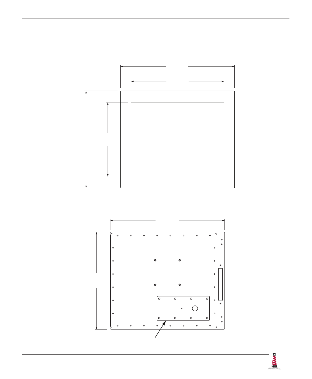
Mechanical Drawings��������������������������������������������������������������������������������������������������������������������5
Front View�������������������������������������������������������������������������������������������������������������������������������5
Rear View �������������������������������������������������������������������������������������������������������������������������������5
Side View ��������������������������������������������������������������������������������������������������������������������������������6
Installation Instructions����������������������������������������������������������������������������������������������������������������7
Step 1: Prepare for Installation ���������������������������������������������������������������������������������������������� 7
Step 2: Bench-test Conguration������������������������������������������������������������������������������������������� 8
Connect Video and Power Cables ����������������������������������������������������������������������������������������������������� 8
Connect and Set Up Touch Screen���������������������������������������������������������������������������������������������������� 9
Step 3: Install the Monitor ���������������������������������������������������������������������������������������������������� 11
Pre-Assembled Workstations������������������������������������������������������������������������������������������������������������11
Install Cable Exit Cover Plate������������������������������������������������������������������������������������������������������������11
Mount the Monitor ���������������������������������������������������������������������������������������������������������������������������� 12
Video Settings������������������������������������������������������������������������������������������������������������������������������15
Setting the Timing Mode ������������������������������������������������������������������������������������������������������� 15
Control Panel Buttons�����������������������������������������������������������������������������������������������������������16
OSD and Power Lock Settings ��������������������������������������������������������������������������������������������� 17
On-Screen Display (OSD) Menus����������������������������������������������������������������������������������������� 18
Auto Image Adjust Menu ������������������������������������������������������������������������������������������������������������������ 19
Contrast / Brightness Menu�������������������������������������������������������������������������������������������������������������� 19
Input Select Menu ���������������������������������������������������������������������������������������������������������������������������� 19
Color Adjust Menu���������������������������������������������������������������������������������������������������������������������������� 20
Information Menu ����������������������������������������������������������������������������������������������������������������������������� 21
Manual Image Adjust Menu�������������������������������������������������������������������������������������������������������������� 21
Setup Menu�������������������������������������������������������������������������������������������������������������������������������������� 22
Memory Recall Menu ����������������������������������������������������������������������������������������������������������������������� 23
Cleaning Instructions������������������������������������������������������������������������������������������������������������������24
Troubleshooting �������������������������������������������������������������������������������������������������������������������������� 25
Video Troubleshooting ����������������������������������������������������������������������������������������������������������25
Touch Screen Troubleshooting ��������������������������������������������������������������������������������������������� 27
Specications ������������������������������������������������������������������������������������������������������������������������������28
Display ����������������������������������������������������������������������������������������������������������������������������������28
Electrical �������������������������������������������������������������������������������������������������������������������������������28
Environmental�����������������������������������������������������������������������������������������������������������������������28
Video�������������������������������������������������������������������������������������������������������������������������������������29
Physical ��������������������������������������������������������������������������������������������������������������������������������29
Functional �����������������������������������������������������������������������������������������������������������������������������30
Compliances and Certications �������������������������������������������������������������������������������������������� 30
Warranty Statement���������������������������������������������������������������������������������������������������������������������31

Safety and Regulatory Information
UM19H User Manual, 99155C, November 2022 3
To prevent re or shock hazard, do not expose live components to rain or moisture.
Dangerously high voltages are present inside the unit� Do not disassemble the
unit. Refer servicing to qualied personnel only. Operator could be exposed to
dangerously high voltage if AC power is not connected properly� Verify all wiring is
properly connected�
This equipment is not intended for use in critical applications where its failure
to operate would create immediate life threatening circumstances� Applications
including, but not limited to, nuclear reactor control, aerospace navigation systems
and life support systems are not appropriate for this product�
To be covered by UL 62368-1, the monitor covered in this report is required to
be used with a Listed computer, and the socket-outlet shall be installed near the
equipment and shall be easily accessible�
DC Supplied Units only: The HIS-UM19 subject unit is to be powered by a Listed
Power Supply suitable for the application with outputs at SELV/LPS or Class 2 levels
rated 9.6-36.6VDC, 2.5 A max. The equipment is not intended to connect directly to
a DC Mains source�
FCC Notice
This equipment has been tested and found to comply with the limits for a Class A digital
device, pursuant to Part 15 of the FCC Rules. These limits are designed to provide
reasonable protection against harmful interference when the equipment is operated
in a commercial environment. This equipment generates, uses, and can radiate radio
frequency energy and, if not installed and used in accordance with the instruction manual,
may cause harmful interference to radio communications� Operation of this equipment
in a residential area is likely to cause harmful interference in which case the user will be
required to correct the interference at his own expense. Any changes or modications not
expressly approved by the grantee of this device could void the user’s authority to operate
the device�
Safety and Regulatory Information
WARNING!
!

Safety and Regulatory Information
4 UM19H User Manual, 99155C, November 2022
Waste Electrical and Electronic Equipment Directive (WEEE)
The following information is only for EU-member states:
The mark shown to the right indicates compliance with the Waste Electrical and
Electronic Equipment Directive 2002/96/EC (WEEE)�
The mark indicates the requirement NOT to dispose of the equipment as unsorted
municipal waste, but use the return and collection systems according to local law. Users
should contact their supplier and check the terms and conditions of the purchase contract�
When purchased directly from Hope Industrial Systems, you may contact technical support
for disposal arrangements.
Hazardous Locations
This equipment is suitable for use in Class I, Division 2, Groups A, B, C, and D; Class II,
Division 2, Groups F and G; Class III; or non-hazardous locations only�
FR: Cet équipement peut être utilisé dans la Classe I, Division 2, Groupes A, B, C et D:
Classe II, Division 2, Groupes F et G; et Classe III, endroits hasardeux ou endroits non-
hasardeux seulement�
WARNING – EXPLOSION HAZARD – Do not disconnect equipment unless power has
been removed or the area is known to be non-hazardous�
WARNING – EXPLOSION HAZARD – Substitution of any components may impair
suitability for Class I, II & III, Division 2 Locations�
NOTE: Hope Industrial Systems provides wiring and conduit that complies with the U.S.
National Electric Code but cannot rate wiring or conduit methods for hazardous locations,
as these must be locally inspected and approved� The customer must install their
hazardous location rated monitor in accordance with the applicable electrical codes for
their location�
YB, PED4X4, and FPED series are not approved for routing internal cables in Class II or
III locations. If these mounting options are desired, customer must route cables outside of
pedestal�
Choose only CP-CON-xx or CP-BLNK-xx cover plate series for Universal Mount Monitors
for hazardous locations�
Any steps marked with this symbol are required to ensure compliance with Class I,
II, III, Division 2 Hazardous Location requirements�
HAZ
LOC

Mechanical Drawings
UM19H User Manual, 99155C, November 2022 5
Mechanical Drawings
Front View
Rear View
467.4 mm
(18.40")
380.8 mm
(14.99")
397.5 mm
(15.65")
305.6 mm
(12.03")
CABLE ENTRY
467.4 mm
(18.40")
397.5 mm
(15.65")

Mechanical Drawings
6 UM19H User Manual, 99155C, November 2022
Side View
198.8 mm
(7.82")
34.3 mm (1.35")
Side Mounting Holes
1/4"-20 Internal Thread
x 0.625" Deep
72.1 mm (2.84")
KEYBOARD
(optional)
KVM EXTENDER
(optional)
176.6 mm
(6.95")
124.5 mm
(4.90")

Installation Instructions
UM19H User Manual, 99155C, November 2022 7
Installation Instructions
Step 1: Prepare for Installation
IMPORTANT!
Perform the following steps BEFORE installation of the monitor.
1� Ensure that sucient power is available and a readily accessible disconnect device is
incorporated in the building installation wiring.
2� Ensure that sucient space is available to allow for proper air ow around the
enclosure�
3� Ensure that the air temperature around the unit (top and bottom) will not exceed the
rated specications of the unit.
fThe maximum rated temperature for the HIS-UM19 is 50°C (122°F).
fRemember that even though this product is designed to operate at
50°C, the life span of any electronic device is shortened when it is
consistently operated at high temperatures. Therefore, it is wise
to take steps to keep the temperature of the ambient air around the
unit as low as possible�
4� Ensure that the ambient humidity of the air around the unit does not exceed the
specications of the unit.
fT h e m a x i m u m r a t e d h u m i d i t y f o r t h e H I S - U M 1 9 i s 9 0 %
non-condensing�
!

Installation Instructions
8 UM19H User Manual, 99155C, November 2022
Step 2: Bench-test Conguration
Make sure everything works before installing into the production environment.
TIP!
If using a KVM extender, please refer to the installation instructions included
with the KVM extender module. It is particularly important to bench-test the full
conguration prior to nal installation. This will help to identify and troubleshoot
any system issues while conguration changes may still be easily made.
Connect Video and Power Cables
The cable ports are located on the rear of the monitor�
Video Connection
The HIS-UM19 supports digital signals (DVI, HDMI, DisplayPort) through its DVI-D port and
analog signals (VGA, RGB) through its VGA port. RGB (BNC, RCA), HDMI, and DisplayPort
video sources require additional adapters�
After selecting the appropriate interface, connect one end of your video cable to the input port
on the rear of the monitor� Secure the screw locks to ensure adequate strain relief� Connect the
other end to the appropriate port on your host computer or other video source�
HAZ
LOC
NOTE: If this step is not performed, the product will not comply with Class I,
II, III, Division 2 Hazardous Location requirements.
TIP!
To avoid incompatibility issues, use only certied video adapters available from
Hope Industrial Systems. Many 3rd-party signal adapters are known to cause
signaling issues�
Power Connection
The HIS-UM19 is available with either AC or DC power input�
AC power input models accept 100 to 240 VAC, 1.5/0.75 A, 60/50 Hz. Loosen the retaining clip
for the power cable on the rear of the monitor� Connect the AC power cable to the power input

Installation Instructions
UM19H User Manual, 99155C, November 2022 9
port on the monitor then retighten the retaining clip. Connect the other end into a nearby outlet.
HAZ
LOC
NOTE: If the retaining clip screw is not tightened, the product will not
comply with Class I, II, III, Division 2 Hazardous Location requirements.
DC power input models accept 9�6 to 36�6 VDC, 2�5 to 0�65 A, Class 2 or SELV/LPS�
1� With main power disconnected, hook up incoming power
wires to the DC input terminal blocks according to the
label markings. Securely tighten terminal block screws.
2� Plug the connector into the unit and secure by tightening
the two side screws�
HAZ
LOC
NOTE: If steps 1 and 2 are not performed, the
product will not comply with Class I, II, III,
Division 2 Hazardous Location requirements.
Connect and Set Up Touch Screen
Applies to touch screen monitors only� Instructions below apply to Windows systems�
Contact Hope Industrial Systems if you require a CD-ROM with documentation and touch screen
drivers. For a full list of downloadable drivers, please check the following address:
https://www�HopeIndustrial�com/support/drivers/
IMPORTANT!
If you will be using a USB connection, install the touch screen driver rst, and then
connect the USB cable. If you will be using a Serial connection, connect the Serial
cable rst, and then install the touch screen driver�
All touch screen models include both USB and Serial (RS-232) ports for touch screen operation,
but only one of these should be connected to the computer� When both ports are available on the
computer, USB is preferred�
Installing the Driver: USB Connections
1� Do not plug the USB connection into the computer until the driver installation is

Installation Instructions
10 UM19H User Manual, 99155C, November 2022
complete� If the USB connection has already been made, disconnect at this point�
2� Download the appropriate driver for your operating system from the address listed
above� Click to "Run" the software when prompted�
3� Follow the on screen prompts to complete the driver installation�
4� Once the driver has been successfully installed, the USB connection can be made by
inserting the connector through the monitor's integrated cable retention bracket and
into the USB port� Connect the other end to the USB port on the host computer�
5� Proceed with Calibration (below)�
Note: detailed and up-to-date USB driver installation instructions can be found at the
following address:
https://www.hopeindustrial.com/blog/calibrating-a-touch-screen/
Installing the Driver: Serial (RS-232) Connections
Serial Connections must be made before installing the driver.
1� Connect one end of the Serial cable to the Serial input port on the rear of the monitor�
Connect the other end to the Serial port on the host computer. Tighten the screw
locks on the cable connectors to ensure adequate strain relief�
HAZ
LOC
NOTE: If this step is not performed, the product will not comply with
Class I, II, III, Division 2 Hazardous Location requirements.
2� Download the appropriate driver for your operating system from the address listed
above� Click to "Run" the software when prompted� Follow the on screen prompts to
complete the driver installation�
3� Proceed with Calibration (below)�
Calibrate the Touch Screen
Once the driver has nished installing, you are ready to calibrate the touch screen.
Open the Windows Control Panel and ensure the "View by" option is set to "Small
icons" in the top right of the window. Click the Elo icon to open the Elo Touchscreen
utility�
Under the "General" tab, click the "Align" button to start the calibration routine.

Installation Instructions
UM19H User Manual, 99155C, November 2022 11
Install Cable Exit Cover Plate
Installation instructions vary slightly depending on the Cable Exit Cover Plate you ordered.
Complete installation instructions are shipped with each Cover Plate conguration and may also
be found on our website at the following addresses:
Conduit Cable Exit (CP-CON Series):
https://www�HopeIndustrial�com/docs/99075
Pilot Hole Cover Plate (CP-BLNK Series):
https://www�HopeIndustrial�com/docs/99077
Compression Gland (CP-GL Series):
https://www�HopeIndustrial�com/docs/99033
Compression Gland (CP-RG Series):
CP-RG1: https://www�HopeIndustrial�com/docs/99071
CP-RG2: https://www�HopeIndustrial�co�uk/docs/99120
Step 3: Install the Monitor
Once you have completed the full bench-test conguration and conrmed that all components are
working properly, you are ready for nal installation and mounting of the monitor.
WARNING!
Hope Industrial will not assume liability for damage to internal electronics due to
improper installation� Contact Hope Industrial if you need additional assistance�
!
Pre-Assembled Workstations
If you purchased a pre-assembled workstation, most of the assembly
has already been performed for you� For your reference, complete
installation instructions are shipped with the workstation should you need to
disassemble or reassemble it for any reason� They may also be found on
our website at the following address:
https://www�HopeIndustrial�com/docs/99108

Installation Instructions
12 UM19H User Manual, 99155C, November 2022
Mount the Monitor
Hope Industrial Systems oers a variety of mounting options for your Universal Mount Monitor.
Individual installation instructions are shipped with the following products and may also be found
on our website at the addresses listed below�
Heavy Industrial Yoke Mounts
The standard yoke may be used alone, with our benchtop mounting kit for
through-surface cable routing, or with our Pedestal Mount for free-standing
applications. Complete installation instructions are shipped with the following
products and may also be found on our website at the following addresses:
Yoke Mounting Hardware:
https://www�HopeIndustrial�com/docs/99025
YB-N12-KIT (for YB _ _ -BLK-N12 Series):
https://www�HopeIndustrial�com/docs/99026
Yoke and Benchtop Mounting Kit (for YB Series):
https://www�HopeIndustrial�com/docs/99027
Heavy Industrial Pedestal Mounts
Our Yoke and Pedestal Mount allows full range of pan and tilt motion. Complete
installation instructions are shipped with the following products and may also be
found on our website at the following addresses:
Yoke Mounting Hardware:
https://www�HopeIndustrial�com/docs/99025
YB-N12-KIT (for YB _ _ -BLK-N12 Series):
https://www�HopeIndustrial�com/docs/99026
Yoke and Benchtop/Pedestal Mounting Kit (for YB and PED4X4 Series):
https://www�HopeIndustrial�com/docs/99027

Installation Instructions
UM19H User Manual, 99155C, November 2022 13
Heavy Industrial Arm Mounts
Our wall arm mounting options range from solid wall yoke to fully
articulating arms. Complete installation instructions are shipped with
the following products and may also be found on our website at the
following addresses:
Wall Mount Arms (for YA _ _ -15 and YA _ _ -24 Series):
https://www�HopeIndustrial�com/docs/99090
Wall Yoke (for YW _ _ -07 Series):
https://www�HopeIndustrial�com/docs/99091
VESA Radial Arm
The VESA Radial Arm Mount is designed to suspend our Universal Mount
Monitors above a working area.
VESA Wall Mount Bracket
The VESA Wall Mount Bracket allows simple, eective mounting of our
Universal Mount Monitors to any vertical surface�
VESA Benchtop Stand
The VESA Benchtop Stand allows easy, stable positioning of our Universal
Mount Monitors on any at surface.

Installation Instructions
14 UM19H User Manual, 99155C, November 2022
All Hope Industrial Universal Mount Monitors come standard with a 100 mm square VESA
mounting pattern with M4 threads. Below is the VESA mounting diagram for Hope Industrial
Universal Mount Monitors. Detailed installation instructions for specic VESA mounting options
are shipped with the product and may also be found on our website at the following address:
https://www�HopeIndustrial�com/docs/99034
If using VESA mounting screws not supplied by Hope Industrial Systems, ensure
they do not intrude into the enclosure more than 12.7 mm (0.5").
IMPORTANT!
UNIVERSAL
MOUNT
MONITOR
NYLON
WASHERS
RUBBER
WASHERS
M4 SCREWS
VESA MOUNTING
PATTERN
(100 mm x 100 mm)
KEYBOARD
(OPTIONAL)
MOUNTING PLATE

Video Settings
UM19H User Manual, 99155C, November 2022 15
Video Settings
Setting the Timing Mode
Setting the timing mode of your computer graphics adapter (or other video source) is important
for maximizing the quality of the screen image and for minimizing eye strain. The timing mode
consists of the resolution (e.g. 1280 x 1024) and refresh rate (or vertical frequency; e.g. 60 Hz).
After setting the timing mode, use the On-Screen Display (OSD) controls to adjust the screen
image.
TIP!
For the best picture quality, set your computer graphics adapter timing mode to:
VESA 1280 x 1024 @ 60 Hz
Please refer to the computer graphics adapter manufacturer's manual for instructions on setting
the resolution and timing mode. In Microsoft Windows, these settings may be found at the
following location:
f2000, XP: Control Panel > Display > Settings
fVista: Control Panel > Personalization > Display Settings
fWindows 7, 8: Control Panel > Appearance and Personalization >
Adjust Screen Resolution
fWindows 10, 11: Start > Settings > System > Display

Video Settings
16 UM19H User Manual, 99155C, November 2022
Control Panel Buttons
Use the control panel buttons located on the back of the monitor to display and adjust various
settings on the On-Screen Display (OSD) menu.
1� To display the Main Menu, press button [1]�
NOTE: All OSD menus and adjustments screens disappear automatically after
15 seconds. This is adjustable through the OSD Time Out setting in the Setup
menu�
2� To select a control to adjust, press the up [▲] or down [▼] button to scroll through the
menu�
3� Press button [2] to open the menu for a selected control�
4� To adjust the control, press the up [▲] or down [▼] button.
5� To save the adjustments and return to the main OSD menu, press button [1] once. To
exit the OSD menu, press button [1] twice�
CONTROL
PANEL
BUTTONS

Video Settings
UM19H User Manual, 99155C, November 2022 17
Button Control Functions
Power • Turns the monitor on and o.
• The Power Indicator light glows blue during normal
operation and orange when the monitor is in Power
Saving mode.
Up / View Mode When the OSD menu IS NOT displayed:
• Shortcut to View Mode�
When the OSD menu IS displayed:
• Scrolls up and adjusts items in the menu up.
Down / Blue Light
Filter
When the OSD menu IS NOT displayed:
• Shortcut to Blue Light Filter.
When the OSD menu IS displayed:
• Scrolls down and adjusts items in the menu down.
Enter When the OSD menu IS NOT displayed:
• Shortcut to Auto Image Adjust.
When the OSD menu IS displayed:
• Displays the control screen for the highlighted control.
Menu • Opens the OSD menu�
• Exits the OSD menu and saves adjustments.
OSD and Power Lock Settings
fOSD Lock: Press and hold [1] and the up [▲] button for 10 seconds. If any buttons
are pressed the message OSD Locked will display for 3 seconds�
fOSD Unlock: Press and hold [1] and the up [▲] button again for 10 seconds.
fPower Button Lock: Press and hold [1] and the down [▼] button for 10 seconds.
If the power button is pressed, the message Power Button Locked will display for 3
seconds. With or without this setting, after a power failure, your monitor's power will
automatically turn ON when power is restored�
fPower Button Unlock: Press and hold [1] and the down [▼] button again for 10
seconds�

Video Settings
18 UM19H User Manual, 99155C, November 2022
On-Screen Display (OSD) Menus
To open the OSD menu, press button [1] once. The following screen will appear:
Main Menu Description
Auto Image Adjust Automatically sizes, centers, and ne tunes the video signal to
eliminate waviness and distortion�
Contrast / Brightness Includes the Contrast and Brightness functions.
Input Select Allows the user to toggle between inputs.
Color Adjust Provides several color adjustment modes.
Information Displays the timing mode (video signal input).
Manual Image Adjust Includes the H� / V� Position, Horizontal Size, Fine Tune,
Sharpness, Aspect Ratio, ECO Mode, View Mode, and Blue
Light Filter functions.
Setup Menu Includes the Language Select, Resolution Notice, OSD Position,
OSD Time Out, OSD Background, Auto Power O, and Power
Indicator functions�
Memory Recall Returns adjustments back to factory settings.

Video Settings
UM19H User Manual, 99155C, November 2022 19
Contrast / Brightness
Menu Description
Contrast Adjusts the dierence between the image background (black
level) and the foreground (white level).
Brightness Adjusts the background black level of the screen image.
Contrast / Brightness Menu
The Contrast / Brightness menu includes the Contrast and Brightness functions.
Input Select Menu
The Input Select menu allows the user to toggle between inputs if there is more than one
computer connected to the display. Use D-Sub for analog VGA signals and DVI for digital signals.
Auto Image Adjust Menu
The Auto Image Adjust menu automatically sizes, centers, and ne tunes the video signal to
eliminate waviness and distortion� Press button [2] outside of the OSD menu to activate Auto
Image Adjust.
NOTE: Auto Image Adjust works with most common video cards. If this function does not work
on your display, lower the video refresh rate to 60 Hz and set the resolution to its pre-set value�

Video Settings
20 UM19H User Manual, 99155C, November 2022
Color Adjust Menu Description
sRGB This is quickly becoming the industry standard for color
management, with support being included in many of the latest
applications. Enabling this setting allows the LCD to more
accurately display colors the way they were originally intended.
NOTE: Enabling the sRGB setting will cause the Contrast and
Brightness adjustments to be disabled.
Bluish Adds blue to the screen image for cooler white (used in most
oce settings with uorescent lighting).
Cool Adds blue to the screen image for cooler white (used in most
oce settings with uorescent lighting).
Native Adds red to the screen image for warmer white and richer red.
Warm Adds red to the screen image for warmer white and richer red.
User Color Individual adjustments for red (R), green (G), and blue (B).
1� To select color (R, G, or B) press button [2]�
2� To adjust selected color, press the up [▲] or down [▼]
button�
NOTE: If you select RECALL from the OSD Main Menu when
the product is set to a Preset Timing Mode, colors return to the
Native factory preset�
Color Adjust Menu
The Color Adjust menu provides several color adjustment modes, including preset color
temperatures and a User Color mode which allows independent adjustment of red (R), green (G),
and blue (B). The factory setting for this product is Native.
This manual suits for next models
1
Table of contents
Other HIS Monitor manuals

HIS
HIS HIS-ML17-xxxB Series User manual

HIS
HIS HIS-UM23.8 Series User manual

HIS
HIS HIS-RL19.5 A Series User manual

HIS
HIS Rack Mount Industrial Monitor HIS-RL17 User manual

HIS
HIS HIS-UM19.5-***A User manual

HIS
HIS HIS-ML23.8 A Series User manual

HIS
HIS HIS-RL15-***H User manual

HIS
HIS HIS-ML17-H Series User manual

HIS
HIS HIS-ML19- *** G User manual

HIS
HIS HIS-ML12 E Series User manual