HIS HIS-ML22 C Series User manual

22" PANEL MOUNT INDUSTRIAL MONITOR
USER MANUAL
Model No. HIS-ML22- _ _ _ C
REVISION C

2 ML22C User Manual, 99176B, September 2021
Table of Contents
Safety and Regulatory Information��������������������������������������������������������������������������������3
FCC Notice �����������������������������������������������������������������������������������������������������������������������������3
Hazardous Locations ��������������������������������������������������������������������������������������������������������������4
Waste Electrical and Electronic Equipment Directive (WEEE) ����������������������������������������������� 4
Mechanical Drawings������������������������������������������������������������������������������������������������������5
Front and Side Views��������������������������������������������������������������������������������������������������������������5
Bottom View����������������������������������������������������������������������������������������������������������������������������5
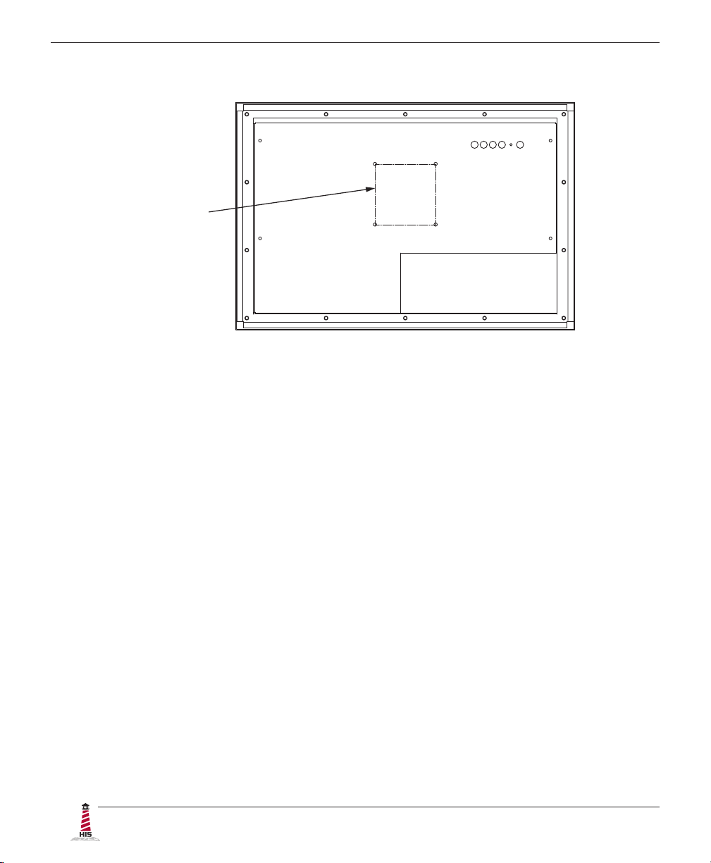
Rear View �������������������������������������������������������������������������������������������������������������������������������6
Installation Instructions��������������������������������������������������������������������������������������������������7
Step 1: Prepare for Installation ���������������������������������������������������������������������������������������������� 7
Step 2: Bench-test Conguration������������������������������������������������������������������������������������������� 8
Install Cable Connections ������������������������������������������������������������������������������������������������������������������ 8
Install Touch Screen Driver �������������������������������������������������������������������������������������������������������������� 10
Step 3: Install into Panel ������������������������������������������������������������������������������������������������������ 12
Video Settings����������������������������������������������������������������������������������������������������������������14
Setting the Timing Mode ������������������������������������������������������������������������������������������������������� 14
Control Panel Buttons����������������������������������������������������������������������������������������������������������� 15
On-Screen Display (OSD) Menus����������������������������������������������������������������������������������������� 17
Picture Menu������������������������������������������������������������������������������������������������������������������������������������ 17
VGA Settings Menu�������������������������������������������������������������������������������������������������������������������������� 19
Setup Menu�������������������������������������������������������������������������������������������������������������������������������������� 20
Cleaning Instructions����������������������������������������������������������������������������������������������������23
Troubleshooting ������������������������������������������������������������������������������������������������������������24
Video Troubleshooting ���������������������������������������������������������������������������������������������������������� 24
Touch Screen Troubleshooting ��������������������������������������������������������������������������������������������� 26
Specications ����������������������������������������������������������������������������������������������������������������27
Display ����������������������������������������������������������������������������������������������������������������������������������27
Environmental����������������������������������������������������������������������������������������������������������������������� 27
Video�������������������������������������������������������������������������������������������������������������������������������������28
Functional �����������������������������������������������������������������������������������������������������������������������������28
Physical ��������������������������������������������������������������������������������������������������������������������������������29
Electrical �������������������������������������������������������������������������������������������������������������������������������29
Compliances and Certications �������������������������������������������������������������������������������������������� 30
Warranty Statement�������������������������������������������������������������������������������������������������������31

Safety and Regulatory Information
ML22C User Manual, 99176B, September 2021 3
Safety and Regulatory Information
To prevent re or shock hazard, do not expose live components to rain or moisture.
Dangerously high voltages are present inside the unit� Do not disassemble the
unit. Refer servicing to qualied personnel only. Operator could be exposed to
dangerously high voltage if AC power is not connected properly� Verify all wiring is
properly connected�
This equipment is not intended for use in critical applications where its failure
to operate would create immediate life threatening circumstances� Applications
including, but not limited to, nuclear reactor control, aerospace navigation systems
and life support systems are not appropriate for this product�
This product is intended to be mounted in a suitable cabinet or other enclosure�
The NEMA 4, 4X, or 12 ratings are applicable only when properly installed in a like
rated enclosure�
To be covered by UL 60950 3rd Edition, the socket-outlet shall be installed near the
equipment and shall be easily accessible�
DC Supplied Units only: The HISML22 subject unit is to be powered by a Listed
Power Supply suitable for the application with outputs at SELV/LPS or Class 2 levels
rated 9.6-36.6VDC, 2.5 A max. The equipment is not intended to connect directly to
a DC Mains source�
FCC Notice
This equipment has been tested and found to comply with the limits for a Class A digital
device, pursuant to Part 15 of the FCC Rules. These limits are designed to provide
reasonable protection against harmful interference when the equipment is operated
in a commercial environment. This equipment generates, uses, and can radiate radio
frequency energy and, if not installed and used in accordance with the instruction manual,
may cause harmful interference to radio communications� Operation of this equipment
in a residential area is likely to cause harmful interference in which case the user will be
required to correct the interference at his own expense. Any changes or modications not
expressly approved by the grantee of this device could void the user’s authority to operate
the device�
WARNING!
!

Safety and Regulatory Information
4 ML22C User Manual, 99176B, September 2021
Waste Electrical and Electronic Equipment Directive (WEEE)
The following information is only for EU-member states:
The mark shown to the right is in compliance with the Waste Electrical and
Electronic Equipment Directive 2002/96/EC (WEEE)�
The mark indicates the requirement NOT to dispose of the equipment as unsorted
municipal waste, but use the return and collection systems according to local law. Users
should contact their supplier and check the terms and conditions of the purchase contract�
When purchased directly from Hope Industrial Systems, you may contact technical support
for disposal arrangements.
Hazardous Locations
This equipment is suitable for use in Class I, Division 2, Groups A, B, C, and D; Class II,
Division 2, Groups F and G; Class III; or non-hazardous locations only�
Device is open-type and is to be installed in an enclosure suitable for the environment that
is only accessible with the use of a tool�
FR: Cet équipement peut être utilisé dans la Classe I, Division 2, Groupes A, B, C et
D: Classe II, Division 2, Groupes F et G; et Classe III, endroits hasardeux ou endroits
non-hasardeux seulement� Cet appareil doit être installé dans un enclos adapté à un
environnement accessible uniquement avec l’aide d’un outil.
WARNING – EXPLOSION HAZARD – Do not disconnect equipment unless power has
been removed or the area is known to be non-hazardous�
WARNING – EXPLOSION HAZARD – Substitution of any components may impair
suitability for Class I, II & III, Division 2 Locations�
Any steps marked with this symbol are required to ensure compliance with Class
I, II, III, Division 2 Hazardous Location requirements�
HAZ
LOC

Mechanical Drawings
ML22C User Manual, 99176B, September 2021 5
Mechanical Drawings
Front and Side Views
Bottom View
311.8 mm
(12.28")
7.1 mm
(0.28")
374.7 mm
(14.75")
558.8 mm
(22.00")
473.8 mm
(18.65")
296.1 mm
(11.66")
558.8 mm
(22.00")
7.1 mm
(0.28")
499.2 mm
(19.65") 53.8 mm
(2.12")
(Design to maximum depth
of 69.0 mm to ensure future
compatibility with later revisions
and replacement units.)

Mechanical Drawings
6 ML22C User Manual, 99176B, September 2021
Rear View
100 mm VESA
Mounting Pattern
(M4 screws provided,
16 mm maximum
depth of screw)

Installation Instructions
ML22C User Manual, 99176B, September 2021 7
Installation Instructions
Step 1: Prepare for Installation
IMPORTANT!
Perform the following steps BEFORE installation of the monitor into the panel.
1� Ensure that sucient power is available.
2� Ensure that sucient space is available to allow for proper air ow into and out of the
unit�
3� Ensure that the air temperature around the unit (top and bottom) will not exceed the
rated specications of the unit.
fThe maximum rated temperature for the HIS-ML22 is 50°C (122°F).
fRemember that heat rises – the temperature at the top of the
cabinet will be much hotter than at the bottom if air inside the
enclosure is not actively circulating. Even in a sealed enclosure,
use of a circulation fan can greatly reduce temperature�
fAlso, remember that even though this product is designed to
operate at 50°C, the life span of any electronic device is shortened
when it is consistently operated at high temperatures. Therefore,
it is wise to take steps to keep the temperature of the ambient air
around the unit as low as possible�
4� Ensure that the ambient humidity of the air around the unit does not exceed the
specications of the unit.
fT h e m a x i m u m r a t e d h u m i d i t y f o r t h e H I S - M L 2 2 i s 9 0 %
non-condensing.
!

Installation Instructions
8 ML22C User Manual, 99176B, September 2021
Step 2: Bench-test Conguration
Make sure everything works before installing into the production environment.
TIP!
If using a KVM extender, please refer to the installation instructions included
with the KVM extender module. It is particularly important to bench-test the full
conguration prior to nal installation. This will help to identify and troubleshoot
any system issues while conguration changes may still be easily made.
Install Cable Connections
All monitors are shipped with a standard VGA video cable� AC-powered displays are also
shipped with a power/mains cable. If you ordered a touch screen monitor, a USB cable is
supplied for the touch screen interface� To use the touch screen Serial (RS-232) interface, a
serial cable may be ordered separately�
The cable ports are located on the rear of the monitor. Refer to the following diagram and
instructions to connect power, video, and touch screen (if applicable) to your monitor�
DVI VIDEO
USB
(for Touch Screen option)
SERIAL
(RS-232)
POWER INPUT
VGA VIDEO

Installation Instructions
ML22C User Manual, 99176B, September 2021 9
Video Connection
The HIS-ML22 supports digital video through its DVI port, and analog video through its VGA port.
After selecting the appropriate interface, connect one end of your video cable to the input port on
the rear of the monitor and secure the screw locks to ensure adequate strain relief� Connect the
other end to the appropriate port on your host computer or other video source�
HAZ
LOC
NOTE: If this step is not performed, the product will not comply with Class I,
II, III, Division 2 Hazardous Location requirements.
TIP!
If the video source has an HDMI or DisplayPort connection, this can be converted
for use with the DVI video port using a simple adapter�
If the video source has a 5 wire analog RGB video output, this can be converted for
use with the VGA video port using a simple adapter�
Certied adapters are available from Hope Industrial Systems. Contact our sales
team for more information�
Power Connection
The HIS-ML22 is available with either AC or DC power input.
AC power input models are powered by 100 to 240 VAC, 1�5/0�75 A, 60/50 Hz� Loosen the
retaining clip for the power cable on the rear of the monitor. Connect the AC power cable to the
power input port on the monitor then retighten the retaining clip. Connect the other end into a
nearby outlet�
HAZ
LOC
NOTE: If this step is not performed, the product will not comply with Class I,
II, III, Division 2 Hazardous Location requirements.

Installation Instructions
10 ML22C User Manual, 99176B, September 2021
DC power input models are powered by 9�6 to 36�6 VDC, 2�5 to 0�65 A, Class 2 or SELV/LPS�
1� With main power disconnected, hook up incoming
power wires to the DC input terminal blocks according
to the label markings. Securely tighten terminal block
screws�
2� Plug the connector into the unit and secure by
tightening the two side screws.
Install Touch Screen Driver
Applies to touch screen monitors only. Instructions below apply to Windows systems. Both USB
and Serial ports are present on all touch screen monitors, but only one should be used to connect
the touch screen interface to the monitor�
Contact Hope Industrial Systems if you require a CD-ROM with documentation and drivers
for touch screens. For a full list of downloadable drivers, please check the following Internet
address:
https://www�HopeIndustrial�com/support/drivers/
IMPORTANT!
If you will be using a USB connection, install the touch screen driver rst, and then
connect the USB cable. If you will be using a Serial connection, connect the Serial
cable rst, and then install the touch screen driver�
USB Connection
1� Select the appropriate driver for your operating system from the web address listed
above�
2� Click to "Run" the software when prompted� Follow on-screen instructions to
download and execute the touch screen driver installation�
3� A cable retention bracket comes installed on the USB port on the rear of the monitor
and will help to secure the cable and ensure adequate strain relief. Without removing

Installation Instructions
ML22C User Manual, 99176B, September 2021 11
the bracket, route one end of the USB cable through the retention bracket and
connect it to the USB input port on the monitor. Connect the other end to the USB
port on the host computer�
HAZ
LOC
NOTE: If this step is not performed, the product will not comply with
Class I, II, III, Division 2 Hazardous Location requirements.
Serial (RS-232) Connection
1� Connect one end of the Serial cable to the Serial input port on the rear of the monitor�
Connect the other end to the Serial port on the host computer. Tighten the screw
locks on the cable connectors to ensure adequate strain relief�
HAZ
LOC
NOTE: If this step is not performed, the product will not comply with
Class I, II, III, Division 2 Hazardous Location requirements.
2� Select the appropriate driver for your operating system from the web address listed
above�
3� Click to "Run" the software when prompted� Follow on-screen instructions to
download and execute the touch screen driver installation�
Calibrate the Touch Screen
Once the driver has nished installing, you are ready to calibrate the touch screen.
Open the Windows Control Panel and ensure the "View by" option is set to "Small
icons" in the top right of the window. Click the Elo icon to open the Elo Touchscreen
utility. Under the "General" tab, click the "Align" button to start the calibration routine.

Installation Instructions
12 ML22C User Manual, 99176B, September 2021
1� Refer to the drawing below for the cutout dimensions for the HIS-ML22.
2�
342.3 mm
(13.48")
528.7 mm
(20.81")
Locate position in panel for mounting of the monitor. Ensure that there is adequate
space behind the panel� Allow extra space – 25�4 mm (1�0") behind and on each
side – for air ventilation�
Step 3: Install into Panel
Once you have completed the full bench-test conguration and conrmed that all components are
working properly, you are ready to install the monitor into its panel cutout.
WARNING!
Hope Industrial Systems will not assume liability for damage to internal electronics
due to improper installation� Contact Hope Industrial Systems if you need additional
assistance�
!

Installation Instructions
ML22C User Manual, 99176B, September 2021 13
3� Cut a rectangular hole in the panel.
fCutout Dimensions (W x H) for the HIS-ML22:
528.7 mm x 342.3 mm (20.81" x 13.48"); ± 0.5 mm (0.020")
4� Clean and deburr the panel hole�
5� Separate the rear collar from the monitor by removing the 14 nuts.
6� Refer to the enclosure mounting diagram below.
7� Insert the unit into the front of the panel and re-attach the collar�
NOTE: Contact Hope Industrial Systems if for any reason your application does
not allow for installation of the collar�
8� Tighten all 14 nuts to a torque of 10-15 inch-pounds to ensure a watertight seal
between the bezel gasket on the monitor and the equipment panel. Go around all
nuts twice to ensure an even compression on gasket.
NOTE: If a torque wrench is not available, tighten all nuts evenly until bezel sits
1.6 to 2.4 mm (1/16" to 3/32") o the front of the panel.

Video Settings
14 ML22C User Manual, 99176B, September 2021
Video Settings
Setting the Timing Mode
Setting the timing mode of your computer graphics adapter (or other video source) is important
for maximizing the quality of the screen image and for minimizing eye strain. The timing mode
consists of the resolution (e.g. 1680 x 1050) and refresh rate (or vertical frequency; e.g. 60 Hz).
After setting the timing mode, use the On-Screen Display (OSD) controls to adjust the screen
image.
TIP!
For the best picture quality, set your computer graphics adapter timing mode to:
VESA 1680 x 1050 @ 60 Hz
Please refer to the computer graphics adapter manufacturer's manual for instructions on setting
the resolution and timing mode. In Microsoft Windows, these settings may be found at the
following location:
f2000, XP: Control Panel > Display > Settings
fVista: Control Panel > Personalization > Display Settings
fWindows 7, 8, 10: Control Panel > Appearance and Personalization >
Adjust Screen Resolution
WARNING!
Do not set the graphics card in your computer to exceed the maximum refresh rate
of 75 Hz; doing so may result in permanent damage to your display.
!

Video Settings
ML22C User Manual, 99176B, September 2021 15
Control Panel Buttons
Use the control panel buttons located on the back of the monitor to display and adjust various
settings on the On-Screen Display (OSD) menu.
1� To open the OSD menu, press the Menu button.
NOTE: All OSD menus and adjustments screens disappear automatically after
60 seconds. This is adjustable through the OSD Time out setting in the Setup
menu�
2� To navigate through the main OSD menu, press the left [◄] or right [►] button.
3� To select a control to adjust, press the Select [ SEL ] button to navigate down through
the menu�
4� To adjust a selected control, press the left [◄] or right [►] button, or press the right
[►] button to open the submenu for a selected control.
5� To return to the main OSD menu, press the Menu button.
6� To exit the OSD menu, press the Menu button.
CONTROL PANEL
BUTTONS

Video Settings
16 ML22C User Manual, 99176B, September 2021
Button Control Functions
Menu • Opens the OSD menu�
• Exits the submenu�
• Exits the OSD menu�
Select /
Navigate Down
When the OSD menu IS NOT displayed:
• Shortcut to Auto setup function�
When the OSD menu IS displayed:
• Navigates down through the OSD menu.
Left / Down /
Brightness
When the OSD menu IS NOT displayed:
• Shortcut to adjust Brightness.
When the OSD menu IS displayed:
• Navigates left in the main OSD menu.
• Decreases adjustments for the selected control.
Right / Up When the OSD menu IS displayed:
• Navigates right in the main OSD menu.
• Displays the submenu for the selected control�
• Increases adjustments for the selected control.
Power Indicator
Light
• LED lit green – power is ON
• LED not lit or lit red – power is OFF
• LED lit orange – monitor is in Standby mode
• LED ashing green – monitor is searching for display
source
Power Turns the monitor on and o.

Video Settings
ML22C User Manual, 99176B, September 2021 17
On-Screen Display (OSD) Menus
To open the OSD menu, press the Menu button once.
Main Menu Description
Picture Includes the Contrast, Brightness, Sharpness, and Color
functions�
VGA Settings Includes the Timing, Auto setup, H total, V position, H position,
and Phase functions�
Setup Includes the Inputs, OSD, Info, Reset to factory defaults, Source
scan, and Advanced Setup functions�
Picture Menu
The Picture menu includes the Contrast, Brightness, Sharpness, and Color functions.
Picture Menu Description
Contrast Adjusts the dierence between the image background (black
level) and the foreground (white level).
Brightness • Adjusts the background black level of the screen image.
• This feature may also be accessed by pressing the left [◄]
button outside of the OSD menu�
Sharpness Adjusts the clarity of the screen to make the image sharper or
softer�

Video Settings
18 ML22C User Manual, 99176B, September 2021
Color Menu
The Color submenu in the Picture menu includes the Auto color, Theme mode, Gamma, Color
balance, and User color functions.
Color Menu Description
Auto color Auto color is an auto adjust routine to compensate, for example,
analog signal level drops on long VGA cables. It needs an input
signal with a picture with black and full color content (white,
red, blue, green). Please contact our support team for further
details�
NOTE: The Auto color function is only available when using the
analog VGA connector.
Theme mode Allows the user to select from three image modes for dierent
usage, as well as the default "O" setting:
• Multimedia optimizes the screen for multimedia
applications, such as video playback�
• Desktop optimizes the screen for desktop applications�
• Gaming optimizes the screen for gaming applications.
Gamma Adjusts the gamma value from 0 to 7. High gamma values
display whitish images and low gamma values display high
contrast images.

Video Settings
ML22C User Manual, 99176B, September 2021 19
Color Menu Description
Color balance Provides several color adjustment modes, including preset
color temperatures and a User color mode that allows individual
adjustment of Red, Green, and Blue. The factory default setting
for this product is Normal�
• User color allows individual adjustment of Red, Green, and
Blue�
• Warm adds red to the screen for warmer white and richer
red�
• Normal is the factory default setting.
• Cold adds blue to the screen image for cooler white.
VGA Settings Menu
The VGA Settings menu includes the Timing, Auto setup, H total, V position, H position, and
Phase functions�
VGA Settings Menu Description
Timing Displays the timing mode (video signal input) coming from the
graphics card in the computer.
Auto setup • Automatically sizes, centers, and ne tunes the video signal
to eliminate waviness and distortion�
• This feature may also be accessed by pressing the Select
[ SEL ] button outside of the OSD menu.

Video Settings
20 ML22C User Manual, 99176B, September 2021
VGA Settings Menu Description
H total Allows the user to ne tune the horizontal timing by increasing
or decreasing the total horizontal pixels. H total aects how the
image is stretched horizontally.
V position (Vertical
Position)
Moves the screen image up and down.
H position (Horizontal
Position)
Moves the screen image left and right.
Phase Adjusts the focus of the screen image. Allows the user
to remove any horizontal noise and sharpen the image of
characters�
Setup Menu
The Setup menu includes the Inputs, OSD, Info, Reset to factory defaults, Source scan, and
Advanced Setup functions�
Setup Menu Description
Inputs Allows the user to select between VGA and DVI input�
This manual suits for next models
12
Table of contents
Other HIS Monitor manuals

HIS
HIS HIS-RL19.5 A Series User manual

HIS
HIS HIS-ML19-***E User manual

HIS
HIS HIS-UM23.8 Series User manual

HIS
HIS HIS-ML17-H Series User manual

HIS
HIS HIS-RL15-***H User manual

HIS
HIS HIS-UM19-H Series User manual

HIS
HIS HIS-UM19.5-***A User manual

HIS
HIS HIS-ML23.8 A Series User manual

HIS
HIS HIS-ML20- *** B User manual

HIS
HIS HIS-ML12 E Series User manual