Hoggi SWINGBO-VTi Operating instructions

en
SWINGBO VTi
Service instructions
Partnerschaft für mobile Kinder

SWINGBO VTi- Service and maintenance instructions
Content Page
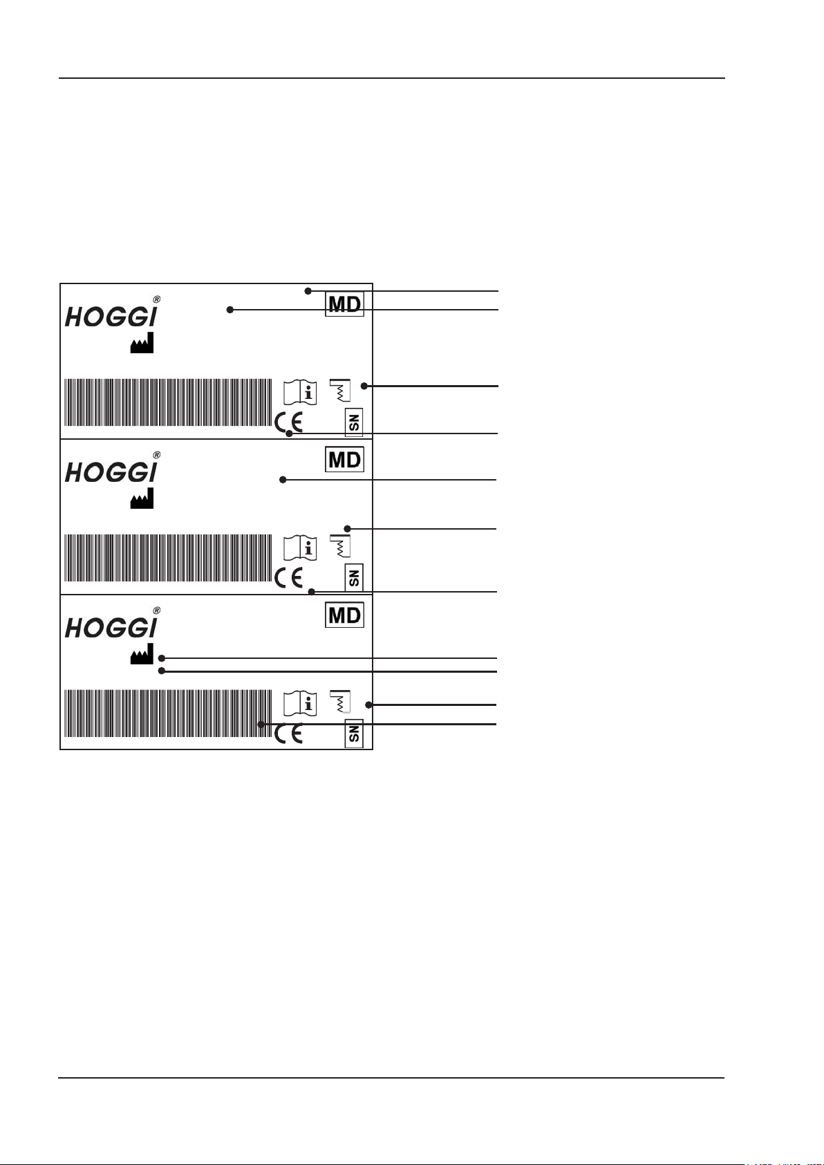
1 Model identication & basic conguration
1.1 Model identication (label)____________________________________________________4-5
1.2 Basic conguration _________________________________________________________4-5
2 Overview SWINGBO VTi__________________________________________________________ 6
3 Common information ____________________________________________________________ 7
3.1 Preface ___________________________________________________________________ 7
3.2 Application_________________________________________________________________ 8
3.3 Declaration of conformity______________________________________________________ 8
3.4 Terms of warranty ___________________________________________________________ 8
3.5 Customer service_ __________________________________________________________ 8
3.6 Service and repairs __________________________________________________________ 9
3.7 Packing and shipping instructions _______________________________________________ 9
4 Safety Instructions _____________________________________________________________ 10
3.1 Meaning of symbols_ _______________________________________________________ 10
3.2 Common safety instructions __________________________________________________ 10
5 Required tools and maintenance schedule _________________________________________ 11
5.1 Required tools _____________________________________________________________ 11
5.2 Maintenance schedule ____________________________________________________12-13
6 Seat settings __________________________________________________________________ 14
6.1 Seat height _____________________________________________________________14-16
6.2 Seat depth ______________________________________________________________16-17
6.3 Active degree _____________________________________________________________ 17
6.4 Back height _____________________________________________________________17-18
6.5 Seat angle______________________________________________________________18-19
6.6 Back angle adjustment ____________________________________________________19-21
6.7 Lower leg length _________________________________________________________21-22
6.8 Footrest angle and depth ____________________________________________________ 22
6.9 Armrest height & angle ____________________________________________________22-23
7 Maintenance schedule __________________________________________________________ 24
7.1 Frame ___________________________________________________________________ 24
7.2 Base plate and cross tube____________________________________________________ 24
7.3 Rear axle _________________________________________________________________ 24
7.4 Seat unit _________________________________________________________________ 25
7.5 Back system & push bar/handle variant _______________________________________25-26
7.6 Braking system __________________________________________________________27-28
7.7 Wheel fork holder ________________________________________________________28-29
7.8 Steering wheel_____________________________________________________________ 29
7.9 Rear wheel _______________________________________________________________ 29
7.10 Push rim _________________________________________________________________ 29

7.11 Fender ___________________________________________________________________ 30
7.12 Anti tip ___________________________________________________________________ 30
7.13 Footrest hanger ____________________________________________________________ 31
7.14 Footrest bracket _________________________________________________________31-32
7.15 Footrests _________________________________________________________________ 32
7.16 Seat and back cushion_ _____________________________________________________ 33
7.17 Tie down kit _______________________________________________________________ 33
7.18 Spoke guards _____________________________________________________________ 33
7.19 Headrest Standard _________________________________________________________ 34
7.20 Headrest with occiput upholstery ______________________________________________ 34
7.21 Thoracic support ___________________________________________________________ 34
7.22 Chest-/ thoracic support _____________________________________________________ 34
7.23 Hip supports ______________________________________________________________ 35
7.24 Abduction block ____________________________________________________________ 35
7.25 Armrests _________________________________________________________________ 35
7.26 Therapy tray ______________________________________________________________ 35
7.27 Belt xations ______________________________________________________________ 36
8 Operating life _________________________________________________________________ 37
9 Specications _________________________________________________________________ 37

4
1Model identication
1.1 Model identication (label)
(The label is attached to the rear axle tube))
Hoggi GmbH
Eulerstr. 27
56235 Ransbach-Baumbach
MADE IN GERMANY
(01)04047349096062(21)202178999
3248-10SB-XXX
SWINGBO VTi
Kantelbarer Rollstuhl
2021178999
2021/05/09
max. load
60kg
Hoggi GmbH
Eulerstr. 27
56235 Ransbach-Baumbach
MADE IN GERMANY
(01)04047349096062(21)202178999
3248-10SB-XXX
SWINGBO VTi
Kantelbarer Rollstuhl
2021178999
2021/05/09
max. load
60kg
Hoggi GmbH
Eulerstr. 27
56235 Ransbach-Baumbach
MADE IN GERMANY
(01)04047349096062(21)202178999
3248-10SB-XXX
SWINGBO VTi
Kantelbarer Rollstuhl
2021178999
2021/05/09
max. load
60kg
Serial number
Classication / Product name
Year of manufacture
UDI Code
Manufacturer
Place of manufacture
Date of manufacture
Maximum load / load capacity
CE label
Colour code
Article number

5
- Aluminium rigid frame with centre of gravity tilt in space
- Wheel base adjustable
- Wheel locks integrated in side panels
- HOGGI light rear wheels incl. push rims (removable via quick release axle)
- Seat depth adjustable by apx. 8 cm
- Choice of seat widths 24 - 36 cm
- Push-handle or push-bar included
- Adjustable front seat height: 36 cm up to 49cm
- Adjustable tilt in space: -5° to +45°
- Back angle adjustable
- Camber 6°, 9° or 12°
- Load capacity: 60 kg
1.2 Basic conguration

6
2 SWINGBO VTi Overview
11
10
12
9
8
5
6
3
2
1
13
7
4
14

7
3 Common Information
3.1 Preface
Thank you for selecting the SWINGBO-VTi wheelchair. We have designed this high-quality
product to make your life safer and easier, and we’ve included this manual to help you use
and care for it. Please read the following instructions to make sure you use this product
as recommended. If you have any further questions, or if you have any problems, please
contact your healthcare provider.
We hope that SWINGBO-VTi meets your expectations.
We reserve technical modi cations regarding the speci ed model in this manual. Before
using the wheechair the rst time, this manual has to be read and understood by patient
and support personnel in oder to ensure a safe handling with the wheelchair.
Regular maintenance is important -it increases safety and prolongs the life of the product.
Every rehab product should be checked and serviced once ayear.
However, it is recommended to check, readjust and, if necessary, service products with
ahigh frequency of use, with users in growth or users with achanging clinical picture at
6-month intervals.
Only original spare parts should be used for all service and maintenance work.
The service and maintenance work described here should only be carried out by trained spe-
cialist personnel and not by the user of the aid.
These service and maintenance instructions refer to the respective spare parts catalogs and
operating instructions of the products described. Please use all documents together.
Use the maintenance schedule (Chapter 5.2, Checklist to tick off) as acopy template.
Retain completed maintenance schedules and provide acopy to the customer.
SWINGBO VTi User manual 1910-0036-EN
SWINGBO VTi Spare parts catalog 1910-0009-EN

8
3.2 Application
SWINGBO VTi wheelchair is designed solely for individual indoor and outdoor use by
childern and adolescents who are unable to walk or who have awalking impediment, and
can be operated by the patient or by another person.
Assistance may be required due to:
-Paralysis (paraplegia /tetraplegia or tetraparesis)
-Loss of limbs (dysmelia/lower limb amputation)
- Infantile/spastic cerebral palsy
- Spina Bida
- Muscle and nerve disorders
- Osteogenesis Imperfecta
- Poliomyeliti
SWINGBO VTi wheelchair is able to be used for further service. For further service the
product has to be cleaned and sanitised efciently. Afterwards the product has to be checked
concerning condition, wearout and damage by an authorised technician. All damaged and
inapropptiate parts need to be changed. Some components can be used again, e.g. rear
wheels, steering wheels or push handles. Please see also the service manual for detailled
information.
3.3 Declaration of Conformity
HOGGI GmbH as manufacturer declares under sole responsibility that the SWINGBO VTi
system wheelchair meets the general safety and performance requirements to Annex I of
the Regulation (EU) 2017/745 of the European Parliament and of the Council. Applicable
harmonized standards have been applied. SWINGBO VTi meets the requirements of ISO
7176-8, DIN EN ISO 12182 and DIN EN ISO 12183.
3.4 Terms of Warranty
Warranty applies only when the product is used according to the specied conditions
and for the intended purposes, following all manufacturer’s recommendations.The
manufacturer is not responsible for damages caused by components and spare parts
not approved by the manufacturer. See also § 8 of terms and conditions on:
www.hoggi.de
3.5 Customer service
Our customer service will be happy to answer any technical questions you may have.
Please refer to the last page for contact addresses and telephone numbers.

9
3.6 Service and repairs
Service and repairs on the SWINGBO VTi wheelchair may only be carried out by your
specialist dealer. In case of problems, contact your responsible specialist dealer. In case of
repairs, you will only receive original spare parts there.
Spare parts and replacement units are available during the entire service life of the pro-
duct, but only for a maximum of 2 years after the sale of the last product in this series.
The wheelchair is custom made for the rst time user. Therefore, no replacement wheel-
chair is available in the initial conguration. In order to ensure a correct spare parts delive-
ry the serial no. of your wheelchair is required.
We are happy to help you nd a dealer near you.
You can reach us at: [email protected]
3.7 Packing and shipping instructions
If SWINGBO VTi has to be sent back to the manufacturer for repair or exchange the pro-
duct must be thoroughly cleaned/disinfected beforehand and put in a hygienically safe
condition.
Packaging is done by wrapping the product in a clean lm, ideally with air cushions and
the subsequent use of a sufciently large cardboard box, so that no transport damage can
occur.

10
4 Safety instructions
4.1 Meaning of symbols
Caution!
Warning of possible danger of accident and injury. Warning of possible technical
damage.
Information!
About use of product.
Information!
For service-personnel.
Attention!
Read manual before use!
4.2 Safety instructions
For all maintenance and repair work, you should generally observe afew points:
Attention!
Familiarize yourself with the functions of the product. If you are not familiar with the
product, study the user manual before testing. If no user manuals are available, request
them from us. You can also download documents from our homepage at: www.hoggi.de
Attention!
Study the service and maintenance instructions before starting work.
Attention!
Use suitable tools (see page 4 ff.).
Attention!
Wear suitable clothing and, if necessary, gloves and protective goggles.
Attention!
Secure the product from tipping over or falling down, e.g. from the workbench.
Attention!
Clean / disinfect the product before starting the test. If necessary, observe the instructions
in the user manual and product-specic test instructions.
Note!
Screws and nuts with thread locking are used for alarge number of screw connections.
If you have to open such screw connections, replace the respective nut or screw with
one with new thread locking. If new nuts or bolts with thread locking are not available,
use liquid thread locking compound with medium strength (e.g. Loctite 241 or Euro Lock
A24.20).

11
5 Required tools and maintenance schedule
5.1 Required tools
The following list shows the tools and utilities required for service.
Reversible ratchet and sockets
size 8-24
Torque wrench
Measuring ranges 5-50 Nm
Wrench
Size 6-24
Hexagon wrench
Gr. 3-6
Screwdriver
Blade width 2.5 3.5 and 5.5
Phillips screwdriver
Size 2
Plastic hammer Hammer approx. 300 gCarpet knife with sickle and
standard blade
Side cutter Liquid thread locking
„medium strength“
Riveting pliers for rivets up to
5mm

12
Maintenance schedule
for regular inspection SWINGBO-VTi
System wheelchair
Customer:
...............................................
Pos. Area Check (Checklist to tick off )
Serial number:
.......................................
1.)
Function / Setting
(see instruction manual)
2.)
none
damage / defor-
mation
3.)
Screw connections
1. Basic product
1.1 Frame - Damages o o o
1.2 Base plates and Cross tube - Active degree
- Seat height
o
o
o o
1.3 Rear axle - Seat height o o o
1.4 Seat unit - Tilt
- Seat depth
o
o
o o
1.5 Back system & push bar/ handle
variant
- Height adjustment back
- Angle adjustment back
- Height adjustment for push bar/
handles
- Angle adjustment for push bar
- Remove
- Fold down
o
o
o
o
o
o
o
o
o
o
o
o
o
o
o
o
o
o
1.6 Braking system - Brakes o o o
1.7 Wheel fork holder - Swivelling of the wheel forks o o o
1.8 Steering wheels - Tires
- Air pressure
- Running behavior of the wheels
o
o
o
o o
1.9 Rear wheels - Tires
- Air pressure
- Running behavior of the wheels
- Camber
- Quick release
o
o
o
o
o
o o
1.10 Push rim - Mounting position o o o
Do the settings on the wheelchair
meet the user‘s requirements? o
Notes:

13
1.)
Function / Setting
2.)
none
damage / defor-
mation
3.)
Screw connections
2. Accessories
2.1 Fender - Height adjustment o o o
2.2 Anti tip and tip assist - Anti tip
- Swivel away
- Angle adjustment
o
o
o
o o
2.3 Footrest hanger - Angle adjustment o o o
2.4 Footrest bracket - Lower leg length
- Folding away the footrest
- Footrest lock
o
o
o
o o
2.5 Footrests - Footrest angle o o o
2.6 Seat / back cushion - Cushion o o
2.7 Tie down kit - Support of the anchorages o o o
2.8 Spoke guards - Spoke guards o o o
2.9 Headrest standard with cushion - Height adjustment
- Padding
o
o
o
o
o
2.10 Headrest with occiput upholstery - Height adjustment
- Angle adjustment
- Padding
o
o
o
o
o
o
o
o
2.11 Thoracic support - Height adjustment
- Width adjustment
- Depth adjustment
- Padding
o
o
o
o
o
o
o
o
o
o
o
2.12 Chest-/ thoracic support - Height adjustment
- Width adjustment
- Depth and angle adjustment
- Padding
o
o
o
o
o
o
o
o
o
o
o
2.13 Hip support - Width adjustment
- Depth adjustment
- Padding
o
o
o
o
o
o
o
o
2.14 Abduction block - Pivot
- Removing
- Padding
o
o
o
o
o
o
o
o
2.15 Armrests - Height adjustment o o o
2.16 Therapy tray - Clamping unit o o o
2.17 Belt xings:
Lap belt, 4-point lap belt, ankle
hugger
- Closures o o o
Do the settings of the accessoires
meet the user‘s requirements? o
Notes
The maintenance was performed by:.............................................................. .on:......................................

14
6. Seat settings
6.1 Seat height
SWINGBO VTi offers seat height adjustment from 37 -47 cm.
The adjustment is inuenced by 3things:
the wheel fork and the correspondingly selected hole position, the axle
position and the seat position.
Axle position
Finally, it is possible to position the axle at different heights. The base
plate offers 6positions of 7.5 mm each.
This results in an adjustment range of 3.75 cm in total.
Seat position
The seat unit can basically be inserted into the upper or lower slotted
hole of the base plate. This results in aseat height difference of 2 cm.
To loosen the seat unit completely, remove the marked screws on both
sides. Then the base plates can be carefully moved apart and the seat
can be removed.
Steering wheel fork and hole position
2different fork types are available. Short or long.
The short fork offers 3hole positions, the long 4.
The holes are spaced 12.5 mm apart, giving an adjustment range of
2.5 cm for the short fork and 3.75 cm for the long fork.

15
Depending on the wheel camber and individual requirements, the following guidelines result:
Rear
wheels SH SH BB AP CF SWP SP AF SH SH BB AP CF SWP SP AF SH SH BB AP CF SWP SP AF
20"
376 37 1short 2deep 2376 37 1short 1deep 2384 38 2short 1deep 2
384 38 2short 3deep 0384 38 2short 2deep 0391 39 3short 2deep 0
396 39 1short high 2396 39 1short high 2404 40 2short 1high 2
404 40 2short 0399 40 4 long 1 deep 1411 41 3short high 0
414 41 6short 3deep 2404 41 2short high 0426 42 5 long 1 high 1
419 42 4short 2high 1414 42 6 long 2 deep 1
434 43 6short 3high 1419 42 4 long 3 high 1
434 43 6 long 2 high 1
22"
394 40 1short 2deep 1
401 40 2 long 2 deep 1401 40 2 long 1 deep 1409 41 3short 3deep 1
416 41 4 long 3 deep 2416 41 4 long 2 deep 2414 42 1short high 1
421 42 2 long 2 high 1421 42 2 long 1 high 1431 43 6 long 3 deep 0
424 43 5 long 4 deep 0424 43 5 long 3 deep 0444 44 5 long 2 high 2
436 44 4 long 3 high 2436 44 4 long 2 high 2451 45 6 long 3 high 0
444 45 5 long 4 high 0444 45 5 long 3 high 0
24"
423 42 1 long 4 deep 0423 42 1 long 3 deep 0423 42 1 long 2 deep 2
443 44 1 long 4 high 0438 43 3 long 4 deep 1431 43 2 long 3 deep 0
443 44 1 long 3 high 0443 44 1 long 2 high 2
458 46 3 long 4 high 1446 45 4 long 4 deep 1
466 47 4 long 4 high 1
SH=Seatheight;SP=Seatposition;AP=Axlepositionn;CF=CasterFork;SWP=Steeringwheelposition;AF=Amount;U-discabovefork
SeatheightsSWINGBO-VTi(3°)
100
125
140
Steeringwheels
Rear
wheels 100 140
SH SH BB AP SP CF SWP OG SH SH BB AP SP CF SWP OG SH SH BB AP SP CF SWP OG Maß
20" 371 37 1deep short 2 0 371 37 1deep short 1 0 378 38 2deep short 1 0
2.3mm
386 38 3deep short 3 0 386 38 3deep short 2 1 393 39 4deep short 2 1
4,3mm
391 39 1high short 2 0 391 39 1hoch short 1 0 398 40 2high short 1 0
2,3
401 40 5deep long 2 1 401 40 5deep short 3 2 408 41 6deep long 1 1
5,8mm
406 41 3high long 1 0 406 41 3high short 2 1 413 42 4high short 1 1
4,3mm
421 42 5high long 2 1 421 42 5high long 1 2 428 43 6high long 1 1
5,8mm
22"
388 39 1deep short 3 2 388 39 1deep short 2 1 395 40 2deep short 2 1
6,3
403 40 3deep long 2 2 403 40 3deep short 3 2 410 41 4deep long 1 2
7,8
410 41 4deep long 3 0 403 40 3deep long 1 2 418 42 5deep long 2 0
2,8
423 42 3high long 2 2 410 41 4deep long 2 0 430 43 4high long 1 2
7,8
425 6deep long 4 1 423 42 3high long 1 2 430 43 4high short 3 2
8,3
430 43 4high long 3 0 430 43 4high long 2 0 438 44 5high long 2 0
2,8
445 44 6high long 4 1 445 44 6high long 3 1
417 42 1deep long 2 0
2,3
24"
425 43 2deep long 4 1 425 43 2deep long 3 1 432 43 3deep long 3 1
4,8
440 44 4deep long 4 2 437 44 1high long 2 0
2,3
445 45 2high long 4 1 445 45 2high long 3 1 452 45 3high long 3 1
4,8
460 46 4high long 4 2 467 46 5high long 4 2
7,3
SH=Seatheight;SP=Seatposition;AP=Axlepositionn;CF=CasterFork;SWP=Steeringwheelposition;AF=Amount;U-discabovefork
SeatheightsSWINGBO-VTi(6°)
Steeringwheels
100
140
125

16
Rear
wheels 100 125 140
SH SH BB AP CF SWP SP AF SH SH BB AP CF SWP SP AF SH SH BB AP CF SWP SP AF
20"
364 36 1short 1deep 2371 37 2short 1deep 0379 38 3short 3deep 0
371 37 2short 2deep 0386 38 4short 2deep 1399 40 3short 3high 0
384 38 1short 1high 2391 39 2short 1hoch 0
391 39 2short hoch 0401 40 6long 1deep 1
401 40 6long 2deep 1406 41 4kurz 2high 1
406 41 4short 3high 1421 42 6long 1high 1
421 42 6long 2high 1
22"
388 39 2long 1deep 1388 39 2long 2deep 1380 38 1short 1deep 1
403 40 4long 2deep 2403 40 4long 1deep 2395 39 3short 2deep 1
410 41 5long 3deep 0410 41 5long 2deep 0400 40 1short 1high 1
423 42 4long 2high 2423 42 4long 1high 2410 41 5long 1deep 2
430 43 5long 3high 0430 43 5long 2high 0418 42 6long 2deep 0
430 43 5long 1high 2
438 44 6long 2high 0
24"
424 42 3long 4deep 1417 42 2long 2deep 2409 41 1long 1deep 2
429 43 1long 3high 0424 43 3long 3deep 1424 42 3long 2deep 2
444 44 3long 4high 0439 44 5long 4deep 2432 43 4long 3deep 0
444 45 3long 3high 1444 44 3long 2high 2
459 46 5long 4high 2447 45 6long 4deep 2
452 46 4long 3high 0
467 47 6long 4high 2
SH=Seatheight;SP=Seatposition;AP=Axlepositionn;CF=CasterFork;SWP=Steeringwheelposition;AF=Amount;U-discabovefork
SeatheightsSWINGBO-VTi(9°)
Steeringwheels
100
125
140
6.2 Seat depth
SWINGBO VTi offers a seat depth adjustment range of 8 cm.
Measured from the outer edge of the backrest plate to the front edge of
the seat plate.
General adjustment range:
VTi 24 - 42 cm
To adjust the seat depth, a total of 4 screws must be loosened.
First, the chair is tilted to 45° to reach and loosen the front screw con-
nections.

17
After the front screw connections have been loosened, the rear screw
connections must be found.
Due to the design of the SWINGBO VTi and the individual seat height
settings, the rear screw connections are not always directly visible.
In this case, the seat unit may have to be moved to adifferent seat
angle position in order to make the screw connection between the
oblong holes visible.
Here it is also possible to work through the hole on the pressure plate
with a4mm Allen key.
The seat plate can then be moved forwards and backwards.
6.3 Active degree
The active degree describes the ratio of the position of the backrest
relative to the drive wheel axis. The further the backrest is set behind
the the drive wheel axle, the more active SWINGBO VTi can be driven.
SWINGBO VTi offers a total active degree adjustment range of 10 cm.
Setting active degree 0-5cm:
If the pressure plate is attached to the base plate as shown, moving the
seat unit results in an adjustment range of 0-5cm.
Setting active degree 6-10 cm:
If alarger active degree range is to be set, both pressure plates must
be loosened and removed.
Then the plates are exchanged from the left side of the chair to the right
and vice versa.
The resulting attachment is shown in the picture.
0 - 10 cm
6.4 Back height
First of all, a distinction must be made between a trough-shaped back-
rest and an angle-adjustable backrest.

18
6.5 Seat angle
The tilt in space of SWINGBO VTi can be adjusted between -5° and
+45°.
13 positions of 4° each can be individually adjusted.
After loosening the indicated screw connections, the back can be
pulled out or pushed in.
After loosening the indicated screw connections, the back can be
pulled out or pushed in.
The angle-adjustable back offers the following ranges:
The trough back offers the following adjustment ranges depending
on the seat width:
Seat width (SW)
Seat width (SW)
Backrest height for
trough shaped back
Backrest height for
angle adjustable back

19
The tilt is triggered by alocking pin pull, which is controlled by arelease
lever on the push bar or push handle.
6.6 Back angle adjustment
The back angle adjustment on the SWINGBO VTi depends on the
selected push bar/push handle variant and the corresponding back.
A distinction must be made here:
Push bar/handles removable with back angle adjustable
The angle of the push handles themselves cannot be adjusted, but they
can be removed for small transport dimensions via clamping levers and
tripod springs.
Depending on how the back panel is screwed to the base, the
adjustment range is either 75°-115° or 80°-120°
If the back plate is screwed in the positions shown on the left,
the adjustment range is 80°-120°.
If the backrest panel is screwed into the positions shown on the right
the adjustment range is 75°-115°.
The back itself offers a total adjustment range of 40° and can be
operated via the release strap on the back.
In addition, the back can be folded forwards for small transport
dimensions.
1. Push bar/handles removable with
angle adjustable back
2. Push bar/handles foldable with back in
trough shape
3. Angle-adjustable and foldable push
bar with trough-shaped backrest
The back sits here in front of the of the
push handles or the push bar and remains
unaffected by their function.
!!

20
The back angle can be set to 5 different angles depending on how it is
screwed to the seat mount.
Front hole: 105°
Second hole: 100°
Third hole: 95°
Fourth hole: 90°
Rear hole: 85°
In addition, the back can also be folded down with the push handles/bars
to achieve a small transport size
To do this, the releases on the left and right are pushed upwards and
then the back is folded down.
Angle-adjustable and foldable push bar with trough-shaped
backrest.
As with the foldable push handles/ bar, only the moulded backrest can
be used!
Push bar/handles foldable with trough-shaped backrest
In contrast to the detachable push handles, the back is directly attached
to the foldable push handles. In addition, the back is always used in the
shape of a trough.
The back with the push handles/bars offers an adjustment range of of
40° and can be operated via the release strap on the back.
Other manuals for SWINGBO-VTi
1
Table of contents
Other Hoggi Wheelchair manuals

Hoggi
Hoggi SWINGBO-VTi User manual

Hoggi
Hoggi SWINGBO-VTi XL Operating instructions

Hoggi
Hoggi SUPRA 2.0 Operating instructions

Hoggi
Hoggi SWINGBO-2 User manual

Hoggi
Hoggi Cesa Operating instructions

Hoggi
Hoggi SHARKY User manual

Hoggi
Hoggi CLEO User manual

Hoggi
Hoggi SHERPA Operating instructions

Hoggi
Hoggi SWINGBO-VTi XL User manual

Hoggi
Hoggi Rehab User manual

Hoggi
Hoggi SWINGBO 2 Operating instructions

Hoggi
Hoggi FARO User manual

Hoggi
Hoggi DURO User manual

Hoggi
Hoggi SHERPA User manual

Hoggi
Hoggi FARO User manual

Hoggi
Hoggi SWINGBO Plus User manual

Hoggi
Hoggi CLEO Teen Operating instructions

Hoggi
Hoggi SWINGBO User manual

Hoggi
Hoggi Basic User manual

Hoggi
Hoggi Cesa User manual