7. OPERATING INSTRUCTIONS
7-1 Attention before operation
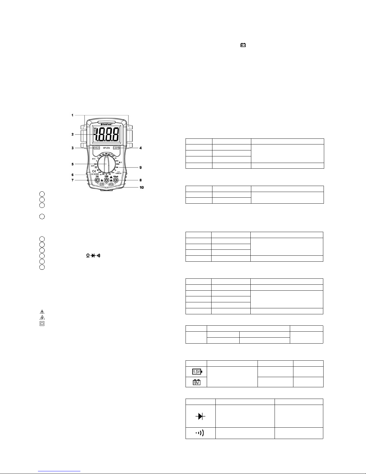
7-1-1 Check battery. When the battery voltage drop below proper
operation range, the “ ” symbol will appear on the LCD display and the
battery need to changed.
7-1-2 Pay attention to the “ ” besides the input jack which shows that the
input voltage or current should be within the specified value.
7-1-3 The range switch should be positioned to desired range for
measurement before operation.
7-2 Measuring DC Voltage
7-2-1 Connect the black test lead to COM jackandtheredtoVΩmA jack.
7-2-2 Set the rotary switch at the desired “V”range position.
7-2-3 Connect test leads across the source or load under measurement.
7-2-4 You can get reading from LCD. The polarity of the red lead
connection will be indicated along with the DC voltage value.
NOTE:
1. When the value scale to be measured is unknown beforehand, set the range
selector at the highest position.
2. When only the figure “1” or “-1” is displayed, it indicates over-range situation and
the higher range has to be selected.
3. “ ” means you can’t input the voltage more than 600V, it’s possible to
show higher voltage, but it may destroy the inner circuit or pose a shock.
4. Be cautious against shock when measuring high Voltage.
7-3 Measuring AC Voltage
7-3-1 Connect the black test lead to COM jackandtheredtoVΩmA jack.
7-3-2 Set the rotary switch at the desired “V”range position.
7-3-3 Connect test leads across the source or load under measurement.
7-3-4 You can get reading from LCD. The polarity of the red lead
connection will be indicated along with the DC voltage value.
NOTE:
1. When the value scale to be measured is unknown beforehand, set the range
selector at the highest position.
2. When only the figure “1” or “-1” is displayed, it indicates over-range situation and
the higher range has to be selected.
3. “ ” means you can’t input the voltage more than 600V, it’s possible to
show higher voltage, but it may destroy the inner circuit or pose a shock.
4. Be cautious against shock when measuring high Voltage.
7-4 Measuring DC Current
7-4-1 Connect the black test lead to COM jackandtheredtotheVΩmA
jack for a maximum 200mA current , for a maximum 10A current, move the
redleadtothe10A jack.
7-4-2 Set the rotary switch at the desired “A”range position.
7-4-3 Connect test leads in series with the load under measurement.
7-4-4 You can get reading from LCD. The polarity of the red lead
connection will be indicated along with the DC current value.
NOTE:
1. When the value scale to be measured is unknown beforehand, set the
range selector at the highest position.
2. When only the figure “1” or “-1” is displayed, it indicates over-range
situation and the higher range has to be selected.
3. “ ” means the socket mA’s maximum current is 200mA and 10A’s
maximum current is 10A, over 200mA current can be protected by the
PPTC resettable fuse, but the 10A range is not fused.
4. On the 10A range, the measuring time should be less than 10 seconds
to prevent precision from affecting by circuit heating.
7-5 Measuring Resistance
7-5-1 Connect the black test lead to COM jackandtheredtoVΩmA jack.
7-5-2 Set the rotary switch at the desired “Ω” range position.
7-5-3 Connect test leads across the resistance under measurement.
7-5-4 You can get reading from LCD.
NOTE: Max. input overload: 250V rms<10sec
1. When only the figure “1” or “-1” is displayed, it indicates over-range
situation and the higher range has to be selected.
2. For measuring resistance above 1M Ω, the mete may take a few
seconds to get stable reading.
3. When the input is not connected, i.e. at open circuit, the figure “1” or “-1”
will be displayed for the over-range condition.
4. When checking in-circuit resistance, be sure the circuit under test has
all power removed and that all capacitors have been discharged fully.
7-6 Measuring Temperature
7-6-1 Connect the black banana plug of the sensor to COM jack and the
red banana plug to the VΩmA jack.
7-6-2 Set the rotary switch at the desired “ ” range position.
7-6-3 Put the sensor probe into the temperature field under measurement.
7-6-4 You can get reading from LCD.
NOTE:
1. The accessory of the meter WRNM-010 type contact thermocouple limit
temperature is 250 (300 shortly), please use special probe for test
higher temperature.
2. Please don't change the thermocouple at will, otherwise we can't
guarantee to measure accuracy.
3. Please don’t importing the voltage in the temperature function.
7-7 Battery Testing
7-7-1 Connect the black test lead to COM jack and the red to VΩmA jack.
7-7-2 Set the rotary switch at the desired “ ”or“ ” range position to
test 1.5V or 9V battery.
7-7-3 Connect test leads across the source or load under measurement.
7-7-4 You can get reading from LCD.
7-8 Diode & Audible continuity Testing
7-8-1 Connect the black test lead to COM jack and the red to VΩmA jack.
7-8-2 Set the rotary switch at the “ ” range position.
7-8-3 On diode range, connect the test leads across the diode under
measurement, display shows the approx. forward voltage of this diode.
7-8-4 On Audible continuity range, connect the test leads to two point
of circuit, if the resistance is lower than approx. 50Ω, the buzzer sounds.
NOTE: Make sure the power is cut off and all capacitors need to be
discharged under this measurement.
8. Battery replacement
1) When the battery voltage drop below proper operation range the " "
symbol will appear on the LCD display and the battery need to changed.
2) Before changing the battery, set the selector switch to “OFF”position.
Open the cover of the battery cabinet by a screwdriver.
3) Replace the old battery with the same type battery (9V 6F22 or NEDA
1604).
4) Close the cover of the battery cabinet and fasten the screw.
9. Maintenance
9-1 Before attempting to remove the battery door or open the case, be
sure that test leads have been disconnected from measurement circuit top
avoid electric shock hazard.
9-2 You must replace the test leads if the lead is exposed, and should
adopt the leads with the same specifications as origin.
9-3 Use only moist fabric or small amount of detergent but not chemical
solution for cleaning.
9-4 Do not use the meter before the back cover is properly closed and
screw secured. Upon any abnormality, stop operation immediately and
send the meter for maintenance.
9-5 Please take out the battery when not using for a long time.
10. Accessories
[1] Test Leads: electric rating 1000V 10A
[2] “K” type thermocouple sensor probe
[3] Operator’s Manual