manuals.online logo
Brands
  1. Home
  2. •
  3. Brands
  4. •
  5. Honeywell Home
  6. •
  7. Security Sensor
  8. •
  9. Honeywell Home PROSiXSMOKEV User manual

Honeywell Home PROSiXSMOKEV User manual

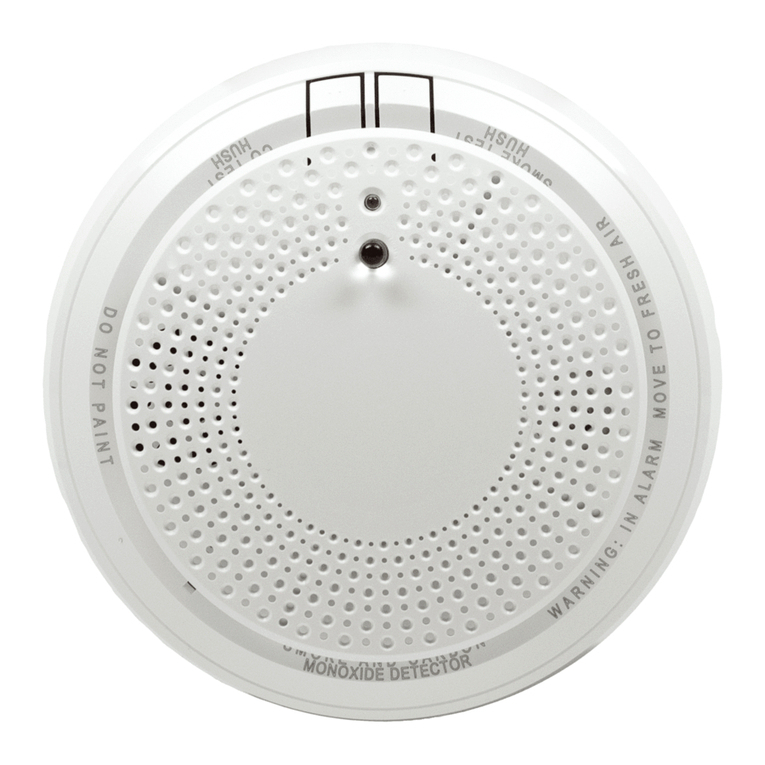
PROSiXSMOKEV
Wireless Smoke/Heat Detector
Installation Instructions
This is a multi-criteria wireless smoke
detector which employs advanced levels
of detection and discrimination to
reduce common cooking nuisance
alarms and faster to different types of
fire conditions. It is intended for use
with Controls that support PROSiX™
series devices.
To remove the mounting bracket, turn
the top of the detector 15 degrees
counterclockwise and separate the
mounting bracket and top cover.
PROSiXSMOKEV
Open
Enrollment
Enroll the device using AlarmNet 360. When prompted, activate the
device by pulling the battery tab or, if already powered, press the
Test button to enroll. It will enroll into 2 zones: smoke detection into
one zone and heat detection into a second zone.
If the detector is not successfully enrolled during the enrollment
period, the LED turns off and the device powers down. Activate the
tamper or press the Test Button to restart the enrollment process.
NOTES: Enrollment time varies depending on the signal strength
between the device and the Control. Once enrolled in a system, the
detector cannot be used with another Control until it is removed from
the current Control. See the Control’s instructions for details.
Enroll
Program
Consult the Control’s instructions to program the device in the system. This detector reports the following signals to the Control:
•Smoke and Heat detection
-Smoke Alarm when smoke is detected
-Heat Alarm when temperature of 135° F (57° C) or greater
-Rate-of-Rise Alarm when temperature is >104° F (40° C) @ 15° F/minute (8.33° C/minute).
•Maintenance: Contaminated chamber that requires cleaning.
•End-of-Life
•Base Tamper: It will send a tamper signal to the control when the smoke head is removed from its base.
•Supervision: 200 second check-in compatible.
•Signal and battery Strength: Signal and battery strength information are sent with every communication to the panel.
NOTE: If programmed in the Control to operate in One-Go-All-Go mode, all smoke detectors programmed as One-Go-All-Go in the
system will sound on alarm.
Tamper
When the detector is removed from its base, it will send a tamper signal to the Control. OPTIONAL: The detector can be made
tamper-proof to prevent unauthorized removal from its base. Break off the small pillar on the base as shown. This will cause the
detector to latch to the base. From this point on, to remove the detector from its base, you must use a small screwdriver to release
the catch (push the catch towards the base) and twist the detector counter-clockwise. A screw can be added to prevent removal
from the base.
Mount
Refer to the Smoke Detector System Application Guide (P/N
SPAG9101) and the Limitations of Fire Alarm Systems (P/N 800-
15144) for detailed information on detector spacing, placement
zoning and special applications. Copies of this document are
available on https://mywebtech.honeywellhome.com/.
NOTE: Before mounting the detector permanently, conduct a Walk
test (see control’s instructions) to verify adequate signal strength
and adjust the device location and orientation as necessary.
The detector can be mounted on the ceiling or on the wall (if local
ordinances permit). Select a location and mount using the included
mounting hardware.
Mount
Testing
The detector should be tested immediately after installation and at least once a year.
Recommended: Notify the Central Station that the smoke detector is undergoing tests, so they do not dispatch authorities.
Tests and testing methods:
There is no specific Test Mode that needs to be entered to test smoke, heat, or Rate-of-Rise. These can be applied to the detector
at any time as a test.
•Test Button –When the Test button is held down, the unit initiates a test on the smoke sensor, chamber, heat sensor, End-of-
Life, and battery. If all tests pass, it sounds a normal alarm and sends alarm signal to the Control. However, if one of these tests
fails, it will send a trouble signal to the Control and provide fail status on the yellow led and sounder.
The Test Button is also used to silence or hush the sounder. To silence the detector, press the large test button or disarm the
system at the Control. The detector sounds again after 10 minutes if the alarm condition still physically exists (smoke in the
chamber). When programmed for One-Go-All-Go mode, the detector can only be silenced from the Control.See the LED and
Sounder Indication Chart on the next page for details.
•Smoke Entry Test (canned smoke*) –Can be done at any time. Once the Chamber is clear, the sounder will stop, and it will
send a restore signal to the Control.
•Direct Heat Test (hair dryer 12” or further from the detector)
-135° F fixed Heat Detection
-Rate-of-Rise >104° F (40° C) @ 15° F/minute (8.33° C/minute).
CAUTION: The detector will alarm when 135° F is exceeded and restore when it falls below 135° F. However, the thermistor will be
damaged at 195° F and the integrity of the detector itself will be compromised and will need to be replaced.
Normal Operation
Action
Green LED
Red LED
Yellow LED
Sounder
Reaction
Power Up
Pull Battery Tab
Rapid flashing up
to 20 seconds
1 Flash
1 Flash
Off
Enrollment
Program into
Control
On for 3 seconds
Off
Off
Off
Processing Control
Queries
Slow flashing
Off
Off
Off
Tamper
Remove from base
Slow flash for
10 minutes
Off
Off
Off
Standby - Normal
1 flash every
60 seconds
Off
Off
Off
Sensing Smoke / Heat
Smoke / Fire
Condition
Off
Rapid flashing
Off
Temporal 3
Evacuate Premises
Alarm Hush
Action
Green LED
Red LED
Yellow LED
Sounder
Reaction
Silence Sounding Alarm
Press & Release
Button
Off
1 flash every
8 seconds
Off
Off for 10 mins
Silence Low Battery
Press & Release
Button
Off
Off
Off for 12 hours
Off for 12 hours
Replace both batteries
Silence Faulty Sensor
(only possible once)
Press & Release
Button
Off
Off
2 flashes every
48 seconds
Off for 12 hours
Replace unit
Silence End of Life (up to
30 days)
Press & Release
Button
Off
Off
Off for 72 hours
Off for 72 hours
Replace unit
Self-Diagnostics
Action
Green LED
Red LED
Yellow LED
Sounder
Reaction
Low Battery ~5Years
Automatic every
16 minutes
Off
Off
1 flash every
48 seconds
1 beep with 1
flash
Replace both batteries
Faulty Smoke Sensor
Automatic every
16 seconds
Off
Off
2 flashes every
48 seconds
2 beeps with 2
flashes
Replace unit
Faulty Heat Sensor
Automatic every
second
Off
Off
2 flashes every
48 seconds
2 beeps with 2
flashes
Replace unit
End of Life ~ 10 Years
Automatic every 4
hours
Off
Off
3 flashes every
48 seconds
3 beeps with 3
flashes
Replace unit
Maintenance
Automatic every
16 seconds
Off
Off
4 flashes every
48 seconds
Off
Clean unit; see Cleaning
section
Test Button
Action
Green LED
Red LED
Yellow LED
Sounder
Reaction
Detector Status Good –
Normal Alarm
Press & Hold
Button
Off
Rapid flashing
Off
Temporal 3
Release button
Low Battery ~5Years
Press & Hold
Button
Off
Off
1 flash then
rapid flashing
1 beep then
Temporal 3
Replace both batteries
Fault Sensor
Press & Hold
Button
Off
Off
2 flashes then
rapid flashing
2 beeps only
Replace unit
End of Life ~ 10 Years
Press & Hold
Button
Off
Off
3 flashes then
rapid flashing
3 beeps then
Temporal 3
Replace unit
Maintenance
Press & Hold
Button
Off
Off
4 flashes then
rapid flashing
4 beeps then
Temporal 3
Clean unit; see Cleaning
section
Alarm Memory
Action
Green LED
Red LED
Yellow LED
Sounder
Reaction
24 Hour Memory
After Alarm
Off
2 flashes every
48 seconds for
24 hours
Off
Off after condition
is physically clear
Press & Hold Button for
Long Term Memory
Long Term Memory
Press & Hold
Button
Off
Rapid flashing
Off
Rapid chirping
Memory is reset after
releasing the test button
LEDs and Sounder
The PROSIXSMOKEV has one green LED and a separate bi-color (red and yellow) LED with an
85dB sounder. Refer to the following table below for operation of these features.
LED and Sounder Indication Chart
Cleaning
Recommended: To prevent unwanted alarms, notify the Central Station
that the smoke detector system is undergoing maintenance before
cleaning the detector.
To clean the detector, carefully vacuum the side vents all the way around,
then, wipe them with a clean damp cloth and dry thoroughly.
Do NOT attempt to take the detector apart. This could result in damaging
the unit.
Cleaning
FEDERAL COMMUNICATIONS COMMISSION (FCC) & INDUSTRY CANADA (IC) STATEMENTS
The user shall not make any changes or modifications to the equipment unless authorized by the Installation Instructions or User's Manual. Unauthorized changes or
modifications could void the user's authority to operate the equipment.
CLASS B DIGITAL DEVICE STATEMENT
This equipment has been tested and found to comply with the limits for a Class B digital device, as defined by FCC Rules Part 15.105. The Class B Digital Device
statement can be viewed at:
https://customer.resideo.com/en-US/support/residential/codes-and-standards/FCC15105/Pages/default.aspx
FCC / IC STATEMENT
This device complies with Part 15 of the FCC Rules, and Industry Canada’s license-exempt RSSs. Operation is subject to the following two conditions: (1) This device
may not cause harmful interference, and (2) This device must accept any interference received, including interference that may cause undesired operation.
Cet appareil est conforme à la partie 15 des règles de la FCC et exempt de licence RSS d’Industrie Canada. Son fonctionnement est soumis aux conditions suivantes:
(1) Cet appareil ne doit pas causer d’interférences nuisibles. (2) Cet appareil doit accepter toute interférence reçue y compris les interférences causant une réception
indésirable.
RF EXPOSURE WARNING –The antenna(s) used for this device must be installed to provide a separation distance of at least 7.8 inches (20 cm) from all persons and
must not be co-located or operating in conjunction with any other antenna or transmitter except in accordance with FCC multi-transmitter product procedures.
Mise en Garde Exposition aux Frequences Radio: L'antenne (s) utilisée pour cet émetteur doit être installée à une distance de séparation d'au moins 7,8 pouces (20
cm) de toutes les personnes.
Responsible Party / Issuer of Supplier’s Declaration of Conformity: Ademco Inc., a subsidiary of Resideo Technologies, Inc., 2 Corporate Center Drive., Melville, NY
11747, Ph: 516-577-2000
REFER TO THE INSTALLATIONINSTRUCTIONS FOR THE CONTROL WITH WHICH THIS DEVICE IS USED, FOR DETAILS REGARDING LIMITATIONS OF THE ENTIRE ALARM SYSTEM.
The Honeywell Home Trademark is used under license from Honeywell International Inc. All other trademarks are the properties of their respective
owners. All rights reserved. This product is manufactured by Resideo and its affiliates.
For the latest documentation and online support information, please go to:
https://mywebtech.honeywell.com/
For the latest warranty information, please go to:
https://www.security.honeywellhome.com/hsc/resources/wa/index.html
For patent information, see https://www.resideo.com/patent
MyWebTech
Warranty
Patents
Ê800-25553AXŠ
800-25553A5/19 Rev A
2 Corporate Center Drive, Suite 100
P.O. Box 9040, Melville, NY 11747
2019 Resideo Technologies, Inc.
www.resideo.com
Battery Replacement
•Twist the front cover counterclockwise
15 degrees and separate it from the mounting
bracket.
•Remove both batteries and wait 10 seconds,
then insert two new recommended batteries:
-Panasonic CR123A
NOTE: Do not mix old and new batteries,
battery types or manufacturers.
•Reattach to the detector to the mounting plate.
Replace Batteries
BATTERY CAUTION: Risk of fire, explosion and burns. Do not recharge, disassemble,
heat above 212° F (100° C) or incinerate. Dispose of used batteries properly. Keep away
from children.
PROSiX/SiX™ Series transmitters draw quick bursts of current during transmission, then sit idle with very nominal current draw. Most batteries are
not designed for this type of use, therefore, only batteries listed as compatible should be used if the expected battery life is to be attained. Each
transmitter’s Installation Instructions has listed compatible battery manufacturers and their part numbers. When other non-approved batteries are
used, the quick bursts of current draw kill the battery cells prematurely causing them to go low in a matter of months and can also cause
unpredictable results. Other low-quality batteries have not been UL tested and pose a safety hazard if used.
Specifications:
Smoke Detection: ..................................................................Photoelectric
Heat Detection: ......................................................................135° F (57° C) or greater +/- 5°F
Rate of Rise: ...........................................................................>104° F (40° C) @ 15° F/minute (8.33° C/minute).
dB Rating:................................................................................>85dBA (Minimum) at 9ft
Batteries: .............................................................................Two 3V Lithium; Panasonic CR123A
RF Frequency: ........................................................................2.4GHz
Tamper:....................................................................................Base Tamper
Operating Temperature: .......................................................40° to 100° F / 4.4° to 37.7° C
Relative Humidity: ..................................................................15% to 95% max, non-condensing
Maximum Spacing: ........................................................50ft x 50ft (refer to National Fire Alarm Code Standard NFPA 72 for application requirements)
Dimensions: ...........................................................................4.5 in. Diameter x 1.7 in. Thick / 11.9 cm Diameter x 4.5 cm Thick
Approval Listings:
FCC / IC
ETL Listed –Conforms to UL 268 7th Edition
cETL Listed –Certified to UL268 & CAN/ULC S529
Other Standards: State of California requirement –free of substances that may cause cancer. Prop 65 US.
NFPA 72
NOTE: Smoke detectors are not to be used with detector guards unless the combination is evaluated and found suitable for that purpose.

Other Honeywell Home Security Sensor manuals

Honeywell Home PROSiXMINI Assembly instructions

Honeywell Home

Honeywell Home PROSiXMINI Assembly instructions

Honeywell Home 5821 User manual

Honeywell Home

Honeywell Home 5821 User manual

Honeywell Home PROSiX Series Assembly instructions

Honeywell Home

Honeywell Home PROSiX Series Assembly instructions

Honeywell Home VISTA-GSM4G Assembly instructions

Honeywell Home

Honeywell Home VISTA-GSM4G Assembly instructions

Honeywell Home HS3PIR2X User manual

Honeywell Home

Honeywell Home HS3PIR2X User manual

Honeywell Home SIXCOMBO-CN User manual

Honeywell Home

Honeywell Home SIXCOMBO-CN User manual

Honeywell Home PROSiXPANIC User manual

Honeywell Home

Honeywell Home PROSiXPANIC User manual

Honeywell Home PROSiXFLOOD Assembly instructions

Honeywell Home

Honeywell Home PROSiXFLOOD Assembly instructions

Honeywell Home 5800PIR-RES Assembly instructions

Honeywell Home

Honeywell Home 5800PIR-RES Assembly instructions

Honeywell Home HS3PIR1X User manual

Honeywell Home

Honeywell Home HS3PIR1X User manual

Honeywell Home CHW3610W User manual

Honeywell Home

Honeywell Home CHW3610W User manual

Honeywell Home C7089R1013 User manual

Honeywell Home

Honeywell Home C7089R1013 User manual

Honeywell Home DO8EZS User manual

Honeywell Home

Honeywell Home DO8EZS User manual

Honeywell Home PROSiXCOMBO Assembly instructions

Honeywell Home

Honeywell Home PROSiXCOMBO Assembly instructions

Honeywell Home 5819S Assembly instructions

Honeywell Home

Honeywell Home 5819S Assembly instructions

Honeywell Home PROSiXCT User manual

Honeywell Home

Honeywell Home PROSiXCT User manual

Honeywell Home PROSiXCOMBOC User manual

Honeywell Home

Honeywell Home PROSiXCOMBOC User manual

Honeywell Home Resideo PROSIXPIR User manual

Honeywell Home

Honeywell Home Resideo PROSIXPIR User manual

Honeywell Home PROSiXCOCN Assembly instructions

Honeywell Home

Honeywell Home PROSiXCOCN Assembly instructions

Honeywell Home FlexGuard 5853 Operating instructions

Honeywell Home

Honeywell Home FlexGuard 5853 Operating instructions

Honeywell Home SiX Series User manual

Honeywell Home

Honeywell Home SiX Series User manual

Popular Security Sensor manuals by other brands

Honeywell FS20X Series Installation guide and operating manual

Honeywell

Honeywell FS20X Series Installation guide and operating manual

PEHA SENSOLUX 482 FU-BM DE Installation and operating instructions

PEHA

PEHA SENSOLUX 482 FU-BM DE Installation and operating instructions

Popp POPE004407 quick start guide

Popp

Popp POPE004407 quick start guide

GESTRA ORGS 11-1 installation instructions

GESTRA

GESTRA ORGS 11-1 installation instructions

Kobold OPT operating instructions

Kobold

Kobold OPT operating instructions

Viavi Seeker HL user guide

Viavi

Viavi Seeker HL user guide

Fire Sentry FS19X-211-213 Installation guide and operating manual

Fire Sentry

Fire Sentry FS19X-211-213 Installation guide and operating manual

STEINEL PROFESSIONAL IS 3360 Information

STEINEL PROFESSIONAL

STEINEL PROFESSIONAL IS 3360 Information

GDI GOLD X-FINDER manual

GDI

GDI GOLD X-FINDER manual

ADEMCO Aurora installation instructions

ADEMCO

ADEMCO Aurora installation instructions

Theben PlanoCentro 000-E Series operating manual

Theben

Theben PlanoCentro 000-E Series operating manual

Trotec BE15 operating manual

Trotec

Trotec BE15 operating manual

IntelliSense FG-1008 installation instructions

IntelliSense

IntelliSense FG-1008 installation instructions

Simplex 4098-9687 installation instructions

Simplex

Simplex 4098-9687 installation instructions

Selcom ST 400 Cayman operating manual

Selcom

Selcom ST 400 Cayman operating manual

Siemens FDT421 installation instructions

Siemens

Siemens FDT421 installation instructions

teko Astra-612 user guide

teko

teko Astra-612 user guide

SureCall Force3 PSB user guide

SureCall

SureCall Force3 PSB user guide

manuals.online logo
manuals.online logoBrands
  • About & Mission
  • Contact us
  • Privacy Policy
  • Terms and Conditions

Copyright 2025 Manuals.Online. All Rights Reserved.