manuals.online logo
Brands
  1. Home
  2. •
  3. Brands
  4. •
  5. Honeywell Home
  6. •
  7. Security Sensor
  8. •
  9. Honeywell Home VISTA-GSM4G Assembly instructions

Honeywell Home VISTA-GSM4G Assembly instructions

– 1 –
VISTA-GSM4G / VISTAGSMCN4G
Module Kit
Installation and Setup Guide
General Information
The VISTA-GSM4G (USA) and VISTAGSMCN4G (Canada)
are optional communication modules intended for use with
the VISTA-21iP control, and provide cellular radio
communication with the AlarmNet network for delivery of
alarm and other messages to the monitoring central station.
These instructions describe the installation of both models,
herein referred to as the “module.”
IMPORTANT!
(1) The VISTA-GSM4G (USA) device requires
activation of its SIM card. See the SIM Activation Note
on page 4 for the procedure.
(2) Use of this module requires an AlarmNet-I account. If
an account for the control does not yet exist, please obtain
the account information from the central station prior to
programming this module.
This kit contains the following components:
IMPORTANT! Disconnect power from the control, including the battery, BEFORE installing the module.
CAUTION: ESD SENSITIVE DEVICE. To discharge any static buildup, briefly touch a chassis ground point before
installing this module. Avoid performing this installation while standing on a carpeted floor.
NOTE: The module is supplied with the antenna adapter cable pre-connected to the module.
Installing the module
1. Mount the Module Board.
a. Push the three standoffs into the appropriate holes on
the VISTA-21iP control board until they snap into place.
b. Carefully align the module board over the standoffs and
the mating connector, then, one at a time, gently push
down on the board near each standoff until it snaps into
place and the connector is fully seated.
c. After installation, affix the “Contains Transmitter
Module” FCC label to the outside surface of the control
panel cabinet so it is visible.
Mounting the module onto the VISTA-21iP PCB
- 2-
2. Install the Antenna Adapter Plate.
a. Punch out the large wiring-hole knockout and the
adjacent smaller knockout from the cabinet’s upper-
right topside.
b. Position the antenna adapter plate over the large
knockout, aligning the plate’s pin with the smaller
knockout and push until the adapter snaps into place.
c. Remove the nut and washer from the antenna adapter
cable then secure the cable’s SMA connector to the
adapter plate with the washer and nut as shown.
OR
3. Install the Antenna.
RF Exposure
Warning – The antenna(s) used for this transmitter must
be installed to provide a separation distance of at least 7.8
inches (20 cm) from all persons and must not be co-located
or operating in conjunction with any other antenna or
transmitter except in accordance with FCC multi-transmitter
product procedures.
The antenna mounts directly onto the antenna adapter cable
at the antenna adapter plate.
Carefully align the antenna’s connector over the SMA
connector protruding from the adapter plate, then screw it
down (clockwise) until it is finger tight. Do not over tighten.
Checking Signal Strength (RSSI)
The Signal Strength (RSSI) / Mode and Status LEDs
normally display the module’s signal strength. LED 1 (red
LED on the top) will be lit to indicate that the display is in
RSSI mode, and the other LEDs indicate signal strength
(lowest to highest, from left to right) between the module and
the receiving tower.
•The signal strength RSSI LEDs will indicate
regardless of whether the SIM is activated. †(If the
SIM is not activated, the red FAULT LED will be lit).
•This allows you to immediately determine if the
desired mounting location has sufficient signal
strength for proper operation.
•For proper operation, look for at least 3 bars lit solid.
†NOTE: The RSSI LEDs on the control board normally
display signal strength after the SIM has been activated (see
note on page 4). If the SIM is not activated, signal strength
can be viewed at these LEDs by simultaneously pressing and
holding the TEST and STATUS switches on the control
board.
NOTE: The module must be activated and registered to
transmit messages to AlarmNet and your central station.
The following are tips for maximizing signal strength:
•The best RSSI can usually be found on an exterior
wall at the highest point in the building. Avoid the
basement.
•Maintain at least 12 inches clearance between
antenna and steel I-beams, HVAC ducts, metal
studs, steel roofs, exterior walls with metalized
insulation or aluminum siding and other large metal
objects.
If a consistent RSSI of three bars cannot be found, the
control cabinet may have to be moved to an area of better
reception.
- 3-
Programming the Module
The module’s parameters are programmed using the control’s
*29 Menu mode. The programming procedure can be found
in the control’s Programming Guide.
To program the module, press ∗29 while in
Programming mode, then follow the prompts.
Monitoring Status & Network Status LEDs
Status LEDs
There are three Status LEDs on the VISTA-21iP PC board
used to indicate message and device status:
•STATUS, green
•MESSAGE, yellow
•FAULT, red
Each LED can have four different states – ON, OFF, FAST
BLINK and SLOW BLINK.
Status LED Meanings
COLOR/LED
DESCRIPTION
Green
Status
On – module NOT registered
Off – module is registered
Fast Blink – Download session with Compass in
progress
Slow Blink – In unison with yellow LED –
Registration in progress.
Yellow
Message
On – Message transmission pending.
Quick Periodic Blink – Normal.
Fast Blink – Message waiting for network ACK.
Slow Blink – In unison with green LED –
Registration in progress.
Red
Fault
On – No contact with network.
Off– Normal.
Slow Blink – Loss of contact with panel (ECP
fault).
Fast Blink – No network contact AND loss of
contact with the panel.
All
Fast Blink – In unison with the RSSI Bar Graph
LEDs – Hardware Error. Call the
AlarmNet Technical Assistance
Center.
Network Status LEDs
Status Indicator Switch
Press and hold the Status LED Indicator Switch to change
the LED functions to view the network carrier status. When
the switch is held down, LED 1 (top red LED) will be off, and
the other LEDs have the following meanings shown in the
Network Status LED Meanings table (See diagram for
specific functions).
Signal Strength and
Network Status LED Meanings
COLO
R
LABEL
INDICATION
Red
RSSI
on = signal strength (RSSI) display
off = status display
Yel (2)
mode
off = module operating in ECP mode
Green
Web
web connection status
Green
GPRS
GPRS service availability
Green
GSM
network carrier registration status
Module Cellular Status LED
The cellular status LED is located on the module’s PC board:
Cellular Status LED
STATUS
BLINK PATTERN
Voice Session
Short blink every second
Data Session
Short blink every 2 seconds
Connected to Cell network
Short blink every 4 seconds
No or deactivated SIM
Long blink every second
Signal Strength and Network Status LED locations – Network Status LED Functions Table
Registering the Control with AlarmNet
Normally, registration with AlarmNet is done at the time the
control is installed. If the module is being installed as an add-
on, the control must be re-registered.
Follow the registration procedure in the control’s Installation
and Setup Guide. A summary of registration steps follows.
Register the control by using one of these methods:
Alpha Keypad using *29 Menu mode
1. Enter *29 Menu mode, select Diagnostic mode, then
use the [↑] shift-B command (D key followed by the
B key). The registration message is sent
(“Registering” displayed) and the control waits for
the acknowledgment.
2. “Registration SUCCESS” displayed, indicating
successful registration.
Test Switch on control’s PCB (triple-click)
1. Click the switch three times.
2. Watch the GSM4G Status LEDs: The Message
(yellow) LED and the Status (green) LED will blink
slowly in unison while registration is in progress.
3. When registration is complete, the Status (green)
LED goes out.
AlarmNet Direct website
See paragraph at right.
By phone
1. Call 1-800-222-6525
You will need the following information:
•MAC ID and MAC CRC number (found on the label
on control’s PC board).
•Subscriber information (provided by the central
station), including a city code, CSID, and a
subscriber ID.
•Activation ID (AID) and AID CRC numbers (found on
the label on the module or on its carton)
2. When instructed to do so, triple-click the Test switch
to complete the registration.
FEDERAL COMMUNICATIONS COMMISSION (FCC) & ISED
The user shall not make any changes or modifications to the equipment unless authorized
by the Installation Instructions or User's Manual. Unauthorized changes or modifications
could void the user's authority to operate the equipment.
FCC / ISED STATEMENT
This device complies with Part 15 of the FCC Rules, and ISED’s license-exempt RSSs.
Operation is subject to the following two conditions: (1) This device may not cause
harmful interference, and (2) This device must accept any interference received, including
interference that may cause undesired operation.
Cet appareil est conforme à la partie 15 des règles de la FCC et exempt de licence RSS
d’ISED. Son fonctionnement est soumis aux conditions suivantes: (1) Cet appareil ne doit
pas causer d’interférences nuisibles. (2) Cet appareil doit accepter toute interférence
reçue y compris les interférences causant une réception indésirable.
SIM ACTIVATION NOTE FOR USA: The VISTA-GSM4G
device is not activated as shipped from the factory
(indicated by unlit RSSI LEDs), and must be activated and
registered before it can be used. To register/activate the
unit, the control in which it is used must be connected to
the Internet via its Ethernet connection or the SIM must be
activated through AlarmNet Direct Website using the AID
number if no internet connectivity is available. After the
module is installed and the control is powered up, use any
of the registration methods to register the control. Upon
successful registration/SIM activation, the RSSI LEDs light
based on signal strength.
For Canadian installations, the VISTAGSMCN4G
includes an activated SIM, but the module must be
registered with AlarmNet before it can be used. Refer to the
Registering the Control with AlarmNet section for
registration procedures.
Registering through AlarmNet Direct Website
To register via AlarmNet Direct Website, please go to:
www.an360.com.
Log in and follow the on-screen prompts.
Please have the following information available:
•Primary City ID (two-digit number provided by central
station)
•Primary Central Station ID (two-digit hexadecimal
number provided by central station)
•Primary Subscriber ID (four-digit number provided by
central station)
•MAC ID and MAC CRC number (located on outside of
box and on label on control’s PC board)
•AID and AID CRC numbers (found on the label on the
module or on its carton).
If you are not signed up for this service, click on “Dealer
Signup” from the login screen to gain access to the
Resideo web-based programming.
Once the control is registered, you may log out of the
AlarmNet Direct website.
ANTENNA SPECIFICATIONS
Type:
Dual band, dipole, PCB
VSWR:
<2:1
Bands:
824-896 MHz
1850-1990 MHz
Impedance:
50 Ohms
Polarization:
Vertical
Dimensions:
185 x 26 mm
Gain (Peak):
0 - 4 dBi
Connector Type:
SMA male
Current Drain (measured at
the Vista-21iP AC input):
60mA average standby,
580mA (rms) peak transmit
Ê800-11810V1BiŠ
800-11810V1B 4/14 Rev B
2 Corporate Center Drive, Suite 100
P.O. Box 9040, Melville, NY 11747
© 2020 Resideo Technologies, Inc.
www.resideo.com

This manual suits for next models

1

Other Honeywell Home Security Sensor manuals

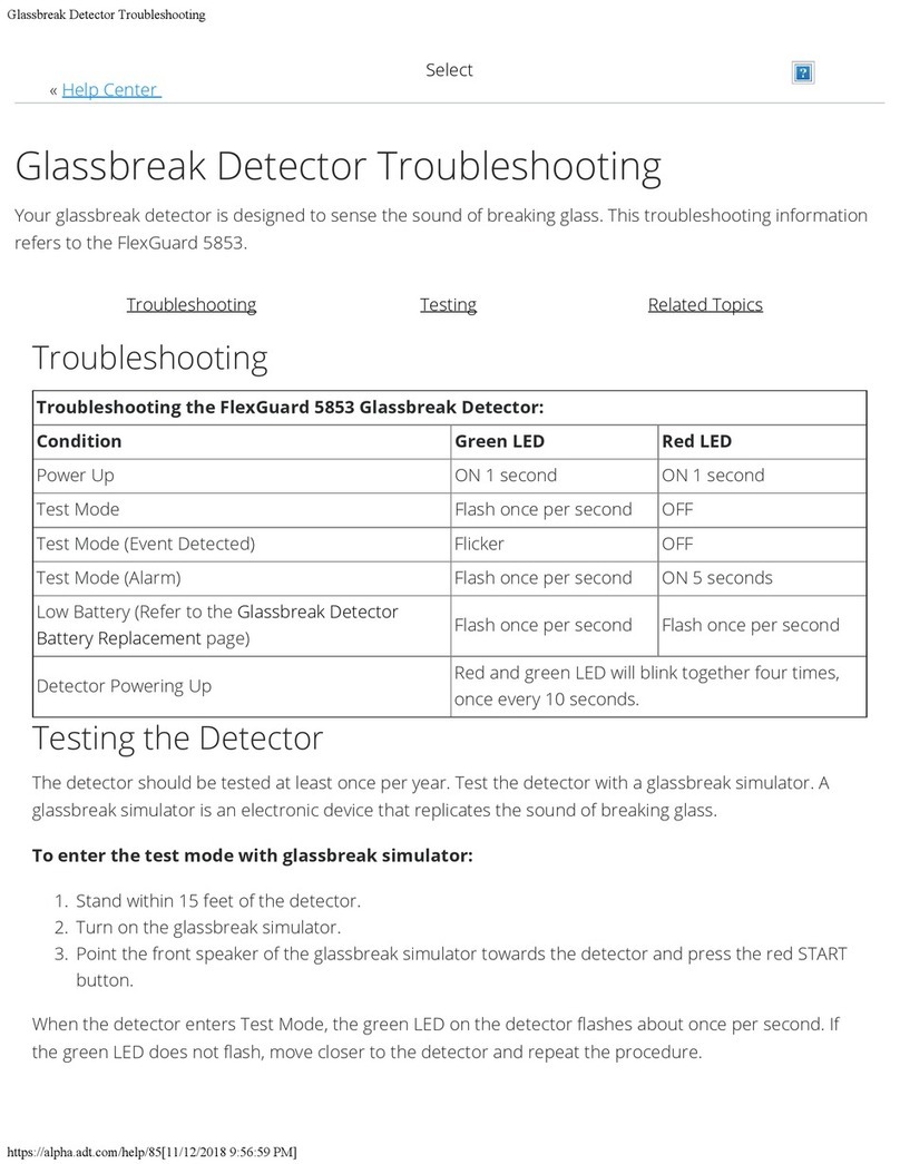
Honeywell Home FlexGuard 5853 Operating instructions

Honeywell Home

Honeywell Home FlexGuard 5853 Operating instructions

Honeywell Home PROSiXCOMBO Assembly instructions

Honeywell Home

Honeywell Home PROSiXCOMBO Assembly instructions

Honeywell Home Resideo PROSIXPIR User manual

Honeywell Home

Honeywell Home Resideo PROSIXPIR User manual

Honeywell Home PROSiXFLOOD Assembly instructions

Honeywell Home

Honeywell Home PROSiXFLOOD Assembly instructions

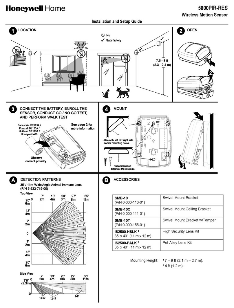
Honeywell Home 5800PIR-RES Assembly instructions

Honeywell Home

Honeywell Home 5800PIR-RES Assembly instructions

Honeywell Home CHW3610W User manual

Honeywell Home

Honeywell Home CHW3610W User manual

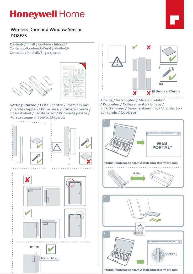
Honeywell Home DO8EZS User manual

Honeywell Home

Honeywell Home DO8EZS User manual

Honeywell Home 5821 User manual

Honeywell Home

Honeywell Home 5821 User manual

Honeywell Home PROSiX Series Assembly instructions

Honeywell Home

Honeywell Home PROSiX Series Assembly instructions

Honeywell Home C7089R1013 User manual

Honeywell Home

Honeywell Home C7089R1013 User manual

Honeywell Home SiX Series User manual

Honeywell Home

Honeywell Home SiX Series User manual

Honeywell Home PROSiXPANIC User manual

Honeywell Home

Honeywell Home PROSiXPANIC User manual

Honeywell Home PROSiXMINI Assembly instructions

Honeywell Home

Honeywell Home PROSiXMINI Assembly instructions

Honeywell Home PROSiXCT User manual

Honeywell Home

Honeywell Home PROSiXCT User manual

Honeywell Home PROSiXCOMBOC User manual

Honeywell Home

Honeywell Home PROSiXCOMBOC User manual

Honeywell Home PROSiXCOCN Assembly instructions

Honeywell Home

Honeywell Home PROSiXCOCN Assembly instructions

Honeywell Home 5819S Assembly instructions

Honeywell Home

Honeywell Home 5819S Assembly instructions

Honeywell Home HS3PIR2X User manual

Honeywell Home

Honeywell Home HS3PIR2X User manual

Honeywell Home SIXCOMBO-CN User manual

Honeywell Home

Honeywell Home SIXCOMBO-CN User manual

Honeywell Home HS3PIR1X User manual

Honeywell Home

Honeywell Home HS3PIR1X User manual

Honeywell Home PROSiXSMOKEV User manual

Honeywell Home

Honeywell Home PROSiXSMOKEV User manual

Popular Security Sensor manuals by other brands

Motorola hmsm4160 quick start guide

Motorola

Motorola hmsm4160 quick start guide

Berker BLC Operation and assembly instructions

Berker

Berker BLC Operation and assembly instructions

Better Water PB2 instructions

Better Water

Better Water PB2 instructions

jablotron JA-159P manual

jablotron

jablotron JA-159P manual

Satel FD-1 quick start guide

Satel

Satel FD-1 quick start guide

Wenglor IR3F001 operating instructions

Wenglor

Wenglor IR3F001 operating instructions

System Sensor 2151 Installation and maintenance instructions

System Sensor

System Sensor 2151 Installation and maintenance instructions

Satel GREY manual

Satel

Satel GREY manual

Honeywell Miller Falcon MP50G-LE User instruction

Honeywell

Honeywell Miller Falcon MP50G-LE User instruction

Baumer URDK 10N8914/S35A quick start guide

Baumer

Baumer URDK 10N8914/S35A quick start guide

Teknim TFD-1260A Installation & user manual

Teknim

Teknim TFD-1260A Installation & user manual

SkyLink WD-101 operating instructions

SkyLink

SkyLink WD-101 operating instructions

Bosch Anatel Professional Series installation instructions

Bosch

Bosch Anatel Professional Series installation instructions

DELTA DORE TYXAL DF installation guide

DELTA DORE

DELTA DORE TYXAL DF installation guide

PCB Piezotronics 132B38/010PH Installation and operating manual

PCB Piezotronics

PCB Piezotronics 132B38/010PH Installation and operating manual

Firefighter EC-FF2-433 Installation manual & users guide

Firefighter

Firefighter EC-FF2-433 Installation manual & users guide

BEA IXIO Series quick guide

BEA

BEA IXIO Series quick guide

Dectris PILATUS3 R Technical Specifications and Operating Procedure

Dectris

Dectris PILATUS3 R Technical Specifications and Operating Procedure

manuals.online logo
manuals.online logoBrands
  • About & Mission
  • Contact us
  • Privacy Policy
  • Terms and Conditions

Copyright 2025 Manuals.Online. All Rights Reserved.