manuals.online logo
Brands
  1. Home
  2. •
  3. Brands
  4. •
  5. Honeywell
  6. •
  7. Computer Hardware
  8. •
  9. Honeywell Gamewell Velociti AMM-4F User manual

Honeywell Gamewell Velociti AMM-4F User manual

MOUNTING
The AMM-4F mounts directly to 4-inch square electrical boxes (see Figure 2).
The box must have a minimum depth of 21⁄8inches. Surface mounted electri-
cal boxes (SMB500) are available from Gamewell-FCI.
FIGURE 2. MODULE MOUNTING:
NOTE: For UL Listed security installations, the AMM-4F must be mounted
within the control panel enclosure.
ISOLATED
QUADRANT
C1066-00
WIRING
NOTE: All wiring must conform to applicable local codes, ordinances, and
regulations. This module is intended for power limited wiring only.
1. Install module wiring in accordance with the job drawings and appropri-
ate wiring diagrams.
2. Set the address on the module per job drawings.
3. Secure module to electrical box (supplied by installer), shown in Figure 2.
Specications
Normal Operating Voltage: 15 to 32 VDC
Maximum Current Draw: 5.0 mA (LED on)
Average Operating Current: 375µA (Velociti Mode); 350µA (CLIP Mode); 600µA; (communicating IDC shorted)
EOL Resistance: 47K Ohms
Maximum IDC Wiring Resistance: 1,500 Ohms
Maximum IDC Voltage: 11 Volts
Maximum IDC Current: 450µA
Temperature Range: 32°F to 120°F (0°C to 49°C)
Humidity: 10% to 93% Non-condensing
Dimensions: 41⁄2˝ H x 4˝ W x 1
1⁄4˝ D (Mounts to a 4˝ square by 21⁄8˝ deep box.)
Accessories: SMB500 Electrical Box
BEFORE INSTALLING
This information is included as a quick reference installation guide. Refer to
the control panel installation manual for detailed system information. If the
modules will be installed in an existing operational system, inform the opera-
tor and local authority that the system will be temporarily out of service. Dis-
connect power to the control panel before installing the modules.
NOTICE: This manual should be left with the owner/user of this equipment.
GENERAL DESCRIPTION
The AMM-4F Monitor Module is intended for use in intelligent, two-wire sys-
tems, where the individual address of each module is selected using the built-
in rotary switches. It provides either a 2-wire or 4-wire fault tolerant initiating
device circuit (IDC) for normally open contact fire alarm and supervisory de-
vices, or either normally open or normally closed security devices. The mod-
ule has a panel controlled LED indicator.
COMPATIBILITY REQUIREMENTS
To ensure proper operation, this module shall be connected to a compatible
Gamewell-FCI system control panel (list available from Gamewell-FCI).
FIGURE 1. CONTROL AND INDICATORS:
C1067-00
INSTALLATION AND MAINTENANCE INSTRUCTIONS
AMM-4F Monitor Module
I56-3553-003
12 Clintonville Road, Northford, CT 06472
(203) 484-7161; Fax: (203) 484-7118
www.gamewell-fci.com
Velociti ®Series
1 I56-3553-003
02-10
FIGURE 3. TYPICAL 2-WIRE INITIATING CIRCUIT CONFIGURATION, NFPA STYLE B:
(+)
(–)
(+)
(–)
(+)
(–)
MONITOR
MODULE
ANY NUMBER OF UL LISTED
CONTACT CLOSURE DEVICES
MAY BE USED. DO NOT MIX FIRE
ALARM INTIATING, SUPERVI-
SORY, OR SECURITY DEVICES
ON THE SAME MODULE.
TO NEXT
DEVICE
FROM PANEL OR
PREVIOUS DEVICE
47K EOL
RESIST
OR
ELR-47K
CONNECT MODULES TO LISTED
COMPATIBLE CONTROL PANELS ONLY
SIGNAL LINE CIRCUIT (SLC)
32 VDC MAX.
TWISTED PAIR
IS RECOMENDED
ALL WIRING SHOWN IS SUPERVISED AND POWER LIMITED
INITIATING DEVICE CIRCUIT (IDC) - NFPA STYLE B
POWER LIMITED: 450µA MAX. @ 11 VDC MAX
INSTALL CONTACT CLOSURE DEVICES PER
MANUFACTURER’S INSTALLATION INSTRUCTIONS.
C1021-00
FIGURE 4. TYPICAL 4-WIRE FAULT TOLERANT INITIATING CIRCUIT CONFIGURATION, NFPA STYLE D:
(+)
(-)
(+)
(–)
(+)
(–)
MONITOR
MODULE
TO NEXT
DEVICE
FROM PANEL OR
PREVIOUS DEVICE
CONNECT MODULES TO LISTED
COMPATIBLE CONTROL PANELS ONLY
SIGNAL LINE CIRCUIT (SLC)
32 VDC MAX.
TWISTED PAIR
IS RECOMENDED
ALL WIRING SHOWN IS SUPERVISED AND POWER LIMITED
ANY NUMBER OF UL LISTED
CONTACT CLOSURE DEVICES
MAY BE USED. DO NOT MIX FIRE
ALARM INTIATING, SUPERVI-
SORY, OR SECURITY DEVICES
ON THE SAME MODULE.
INSTALL CONTACT CLOSURE DEVICES PER
MANUFACTURER’S INSTALLATION INSTRUCTIONS.
EOL RESISTOR
IS INTERNAL AT
TERMINALS 8
AND 9
C1022-00
2 I56-3553-003
©2017 Honeywell. 02-10
Velociti®, Gamewell-FCI®, System Sensor®, and Honeywell®are registered trademarks of Honeywell International, Inc.

Other Honeywell Computer Hardware manuals

Honeywell WEB-O3022H Operation manual

Honeywell

Honeywell WEB-O3022H Operation manual

Honeywell 66 User manual

Honeywell

Honeywell 66 User manual

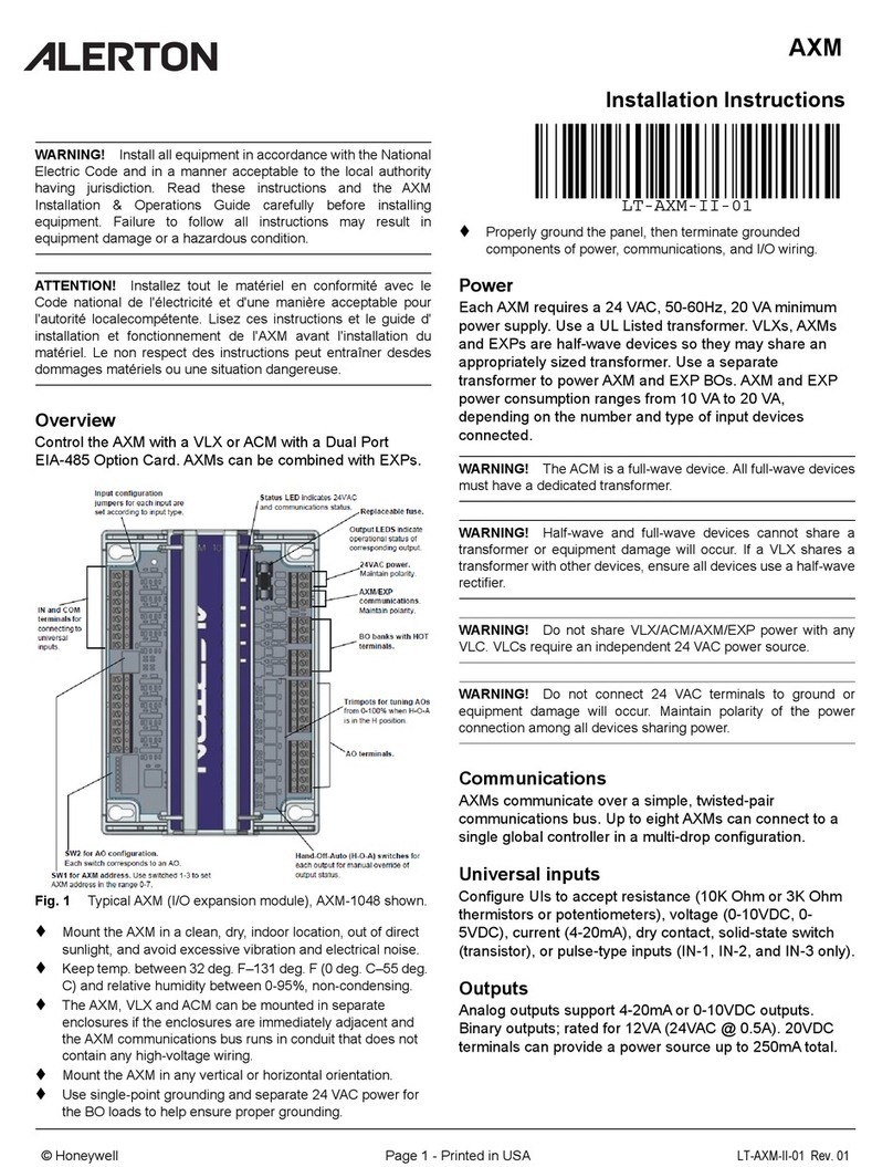
Honeywell ALERTON AXM User manual

Honeywell

Honeywell ALERTON AXM User manual

Honeywell GENT VSINTM-PCB-UPG User manual

Honeywell

Honeywell GENT VSINTM-PCB-UPG User manual

Honeywell PW7K1R1E Operator's manual

Honeywell

Honeywell PW7K1R1E Operator's manual

Honeywell PW7K1R1 User manual

Honeywell

Honeywell PW7K1R1 User manual

Honeywell RS-485 User manual

Honeywell

Honeywell RS-485 User manual

Honeywell RM7895 Series Manual

Honeywell

Honeywell RM7895 Series Manual

Honeywell HX3 User manual

Honeywell

Honeywell HX3 User manual

Honeywell PX4ie User manual

Honeywell

Honeywell PX4ie User manual

Honeywell RM7838B Series User manual

Honeywell

Honeywell RM7838B Series User manual

Honeywell NX series User manual

Honeywell

Honeywell NX series User manual

Popular Computer Hardware manuals by other brands

Alpha Data ADM-SDEV-BASE/XCKU060 user manual

Alpha Data

Alpha Data ADM-SDEV-BASE/XCKU060 user manual

Protech Systems BH-1105 Quick reference guide

Protech Systems

Protech Systems BH-1105 Quick reference guide

LAPIS Semiconductor ML62Q1577 user manual

LAPIS Semiconductor

LAPIS Semiconductor ML62Q1577 user manual

EK Nucleus AIO CR360 Lux Direct Die D-RGB -... instruction manual

EK

EK Nucleus AIO CR360 Lux Direct Die D-RGB -... instruction manual

Manhattan 702997 user manual

Manhattan

Manhattan 702997 user manual

NEC IE-784000-R user manual

NEC

NEC IE-784000-R user manual

MSI P55-GD61 Series manual

MSI

MSI P55-GD61 Series manual

ekwb EK-FC R9-280X DCII installation manual

ekwb

ekwb EK-FC R9-280X DCII installation manual

Emotiva DMC-1 user guide

Emotiva

Emotiva DMC-1 user guide

Leviton 17A00-9 Installation instructions and user guide

Leviton

Leviton 17A00-9 Installation instructions and user guide

Advantech UNO-3300G Series user manual

Advantech

Advantech UNO-3300G Series user manual

Lexicon MPX - ADDENDUM REV 1 datasheet

Lexicon

Lexicon MPX - ADDENDUM REV 1 datasheet

Nvidia DGX A100 Service manual

Nvidia

Nvidia DGX A100 Service manual

Renesas R8C/2F quick start guide

Renesas

Renesas R8C/2F quick start guide

Maxim Dallas DS87C530 Specification sheet

Maxim

Maxim Dallas DS87C530 Specification sheet

Crown IQ P.I.P.-DSP Reference manual

Crown

Crown IQ P.I.P.-DSP Reference manual

Panasonic KX-W1000 Service manual

Panasonic

Panasonic KX-W1000 Service manual

ST STEVAL-ST25R3916B user manual

ST

ST STEVAL-ST25R3916B user manual

manuals.online logo
manuals.online logoBrands
  • About & Mission
  • Contact us
  • Privacy Policy
  • Terms and Conditions

Copyright 2025 Manuals.Online. All Rights Reserved.