manuals.online logo
Brands
  1. Home
  2. •
  3. Brands
  4. •
  5. Honeywell
  6. •
  7. Computer Hardware
  8. •
  9. Honeywell GENT VSINTM-PCB-UPG User manual

Honeywell GENT VSINTM-PCB-UPG User manual

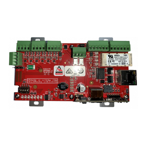
These instructions cover the installation of a
Replacement Mains Interface Board on a carrier
(VSINTM-PCB-UPG) into a legacy 34440 Mains
powered interface unit.
Spare Parts Qty
Fuse 3.15A AS Ceramic
(20mm x 5mm)
1
Fuse 3.15A QB Glass
(20mm x 5mm)
1
Resistor 5.6K 0.6W 4
Resistor 470R 0.6W 8
Resistor 10K 0.5W 4
Battery Link 1
Battery Lead 1
Capacitor 22uF 35V 4
Screw
(for fixing the carrier)
4
Instructions 1
4188-1005 issue 1_03/11_Replacement Board for 34440 MPI 1
Installation
Replacement Interface Board
(VSINTM-PCB-UPG) for 34440 Interface
by Honeywell
PB2
S+ Z+ Z-S-
SECTOR / ZONE1
PB3
S+ Z+ Z-S-
SECTOR / ZONE2
PB4
S+ Z+ Z-S-
SECTOR / ZONE3
PB5
S+ Z+ Z-S-
SECTOR / ZONE4
PB1
0C LC 01 L1 02 L2
LOOP LN
PB6
++--
AUX O/P
P3
FS6
T3.16A
CERAMIC
ANTI-SURGE
SW1-POWERUP
P7
Mains Powered
Interface Unit Mk 3
P1
DANGER
DO NOT
REMOVE
FS8 F3.16A
QUICK
BLOW
Product No. 34440 REV 2
Nominal Voltage rating 230VAC
Rated Frequency 50-60Hz
Rated Current 0.7A
Manufacture Date XX/XX
LN
P3
P7
DIN RAIL FOR OPTIONAL
OCTAL TYPE RELAYS
34440 Mains Interface Board
MAINS
TERMINAL
BLOCK
EARTH
TO DOOR
DOOR
BATTERY
RESTRAINT
FIXING POINT
2-OFF
12V 2.1Ah
BATTERIES
NEL
P3 P4 P5 P6 P2
AC AC
P7 Aux
P9
Battery
P8
+- +-
FS1 FS2 FS3 FS4
FS5
FS6
S5
PB2
S+ Z+ Z-S-
SECTOR / ZONE1
PB3
S+ Z+ Z-S-
SECTOR / ZONE2
PB4
S+ Z+ Z-S-
SECTOR / ZONE3
PB5
S+ Z+ Z-S-
SECTOR / ZONE4
PB1
0C LC 01 L1 02 L2
LOOP LN
PB6
++---
AUX O/P
P3
FS6
T3.16A
CERAMIC
ANTI-SURGE
SW1-POWERUP
P7
Mains Powered
Interface Unit Mk 3
P1
DANGER
DO NOT
REMOVE
FS8 F3.16A
QUICK
BLOW
P8
Replacement Mains Interface Board on carrier
P9
P7
MAINS FILTER TRANSFORMER
TERMINAL BLOCK
TRANSFORMER
#
#
*
Use the screw supplied for
fixing the carrier and to maintain
Earth continuity.
*
**
*
34440 Mains powered interface unit
#
Ensure these screws are securely fitted,
they provide earth continuity to the enclosure.
CARRIER
BOARD
Product No. 34440 REV 2
Nominal Voltagerating 230VAC
Rated Frequency 50-60Hz
Rated Current 0.7A
Manufacture Date XX/XX
LN
Removal
a. Use the [Test/Eng] menu at the control panel and [Stop] the loop circuit on which the 34440 Mains
powered interface unit reside.
&Before removal of the 34440 Mains Interface Board from the 34440 Mains powered interface unit,
first completely isolate the mains supply to the unit. Disconnect the wired connection to the Batteries and
then disconnect the battery lead from terminal P8 kon the Board.
b. Now disconnect all the wires uvwxy and zbetween the MAINS TERMINAL BLOCK and AC
terminals P7 lon the 34440 Mains interface board. Remove the MAINS TERMINAL BLOCK, MAINS
FILTER, TRANSFORMER TERMINAL BLOCK and the TRANSFORMER jfrom the enclosure and
discard them safely.
c. Mark all the other external wires before disconnecting them from their terminal blocks m, this will help
identify the cables for reconnection to the Replacement Mains Interface Board.
d. Remove 34440 Mains Interface Board from the unit nand discard it safely.
Programming
"The Replacement Mains Interface Board is factory configured with all four channels as 'Sector' outputs.
Use the S4 Interface Programmer kit (S4-INTERFACE-PROG) V1.03 or greater and configure the required
'Zone' inputs and 'Sector' outputs on the Replacement Interface Board, in order to simulate the legacy 34440
Mains Interface Board, see instructions supplied with the S4 Interface Programmer kit.
Installation Replacement Mains Interface Board
2 4188-1005 issue 1_03/11_Replacement Board for 34440 MPI
MAINS
TERMINAL
BLOCK
N
MAINS FILTER
TRANSFORMER TERMINAL BLOCK TRANSFORMER
AC AC
P7
34440 Mains Interface Board
L
34440 Mains powered interface unit
Battery
P8
+-
+
-
-
+
2 - 12V 2.1Ahr BATTERIES
Replacement
a. The external mains cable should be rewired so that it enters the enclosure above the Mains terminal
block on the Replacement Mains Interface Board, this ensures there is segregation between mains and
extra low voltage cables. Also, each unused cable entry point must be fitted with a plastic bung.
b. Fit the Replacement Mains Interface Board on a carrier into the enclosure ousing the screws supplied.
&Ensure the board fixing screws are securely fitted as they form part of an earth continuity path to
the metal enclosure, this is necessary for electrical safety and for EMC compliance.
c. Reconnect the external wiring to the terminal blocks pand qon the Replacement Mains Interface
Board.
d. Check and ensure the correct End Of Line units are fitted for the respective Zone and Sector circuits.
e. Switch ON the mains supply to the Unit and then connect the battery lead to the batteries and to
connector P7 on the Replacement Mains Interface Board.
f. Using the [Test/Eng] menu at the control panel [Allocate] the loop circuit, on which the Interface unit is
connected. The interface unit should then be tested to site specific requirements.
g. Close the enclosure door and lock it using the key.
4188-1005 issue 1_03/11_Replacement Board for 34440 MPI 3
Replacement Mains Interface Board Installation
PB1
0C LC 01 L1 02 L2
LOOP
LOOP OUT
LOOP IN
LOOP
SPUR
PB6
++--
AUX O/P
External
Equipment
PB2, PB3,
PB4orPB5
S+ S-
SECTOR1,2,3or4
10K EOLW
IS Sector Output
IS Galvanic
isolator (02518-10)
PB2, PB3,
PB4orPB5
Z+ Z-
ZONE 1, 2, 3 or 4
22uF EOL
Zone Input
PB2, PB3,
PB4orPB5
Z+ Z-
ZONE 1, 2, 3 or 4
5K6 EOL
IS Zone Input
PB2, PB3,
PB4orPB5
S+ S-
SECTOR1,2,3or4
10K EOLW
Sector Output
with Sounders
PB2, PB3,
PB4orPB5
S+ S-
SECTOR1,2,3or4
10K EOLW
Flyback
diode
Sector Output
with Inductive
load (eg Relay)
IS Galvanic
isolator (17740-30)
Auxiliary Output: 0.25A
11+ 12-
1+ 2-
12 11
21
Connected to
metal enclosure
End-of-line units
Capacitor 22uF
Resistor 470W
yellow, violet, brown
Resistor 5K6KW
green, blue, red
Resistor 10KW
Brown, black, orange
To avoid damage to equipment always
configure the interface inputs and
outputs before connecting the external
circuits.
Intrinsically
safe devices
Intrinsically
safe devices
cable length max.150m
cable length
max.150m
cable length
max.150m
The combined maximum total current
load for sectors and auxiliary output
is 0.5A.
Terminals on a 34440 Mains Interface Board
Terminals on a Replacement Mains Interface Board (VSINTM-PCB-UPG)
Installation Replacement Mains Interface Board
Gent by Honeywell reserves the right to revise this publication from time to time and make changes to the content hereof without
obligation to notify any person of such revisions of changes.
Hamilton Industrial Park, Waterside Road, Leicester LE5 1TN, UK Website: www.gent.co.uk
Telephone: +44 (0) 116 246 2000 Technical support: www.gentexpert.co.uk Fax (UK): +44 (0)116 246 2300
4 4188-1005 issue 1_03/11_Replacement Board for 34440 MPI
by Honeywell
At the end of their useful life, the packaging,
product and batteries should be disposed of
via a suitable recycling centre and in
accordance with national or local legislation.
Do not dispose of with your normal household waste.
Do not burn.
WEEE Directive:
At the end of their useful life, the packaging,
product and batteries should be
disposed of via a suitable recycling centre.
24V 2.1Ahr BATTERIES
+
-
-
PB2
S+ Z+ Z-
S-
SECTOR / ZONE1
PB3
S+ Z+ Z-
S-
SECTOR / ZONE2
PB4
S+ Z+ Z-
S-
SECTOR / ZONE3
PB5
S+ Z+ Z-
S-
SECTOR / ZONE4
PB1
0C LC 01 L1 02 L2
LOOP WIRING
LN
PB6
++
--
AUX O/P
P3
P7
Replacement Mains Interface Board
(VSINTM-PCB-UPG)
+
NE L
CONNECTION TO
THE TRANSFORMER
P3 P4 P5 P6 P2
P9 P8
34440 Mains Interface Board
P7
24V DC SUPPLY
FUSED AT 250mA
+-
2 x 12V 2.1Ahr BATTERIES
+-
BATTERY
AUX
+
-
-
+
Z3 ZC3-S3+S3 Z4 ZC4-S4+S4Z2 ZC2-S2+S2Z1 ZC1-S1+S1 LC0V L10V L20V
LOOP WIRING
~~

Other Honeywell Computer Hardware manuals

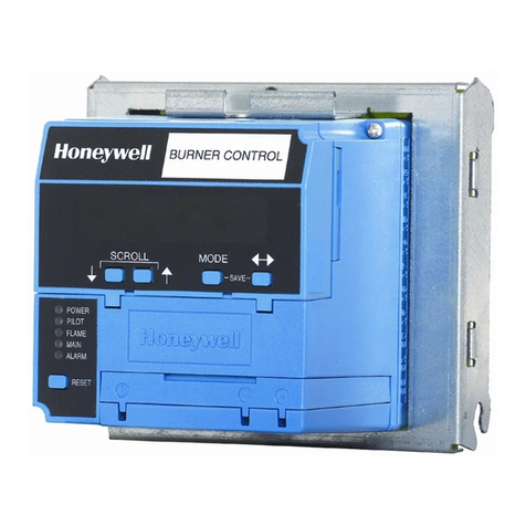
Honeywell RM7838B Series User manual

Honeywell

Honeywell RM7838B Series User manual

Honeywell PW7K1R1E Operator's manual

Honeywell

Honeywell PW7K1R1E Operator's manual

Honeywell RM7895 Series Manual

Honeywell

Honeywell RM7895 Series Manual

Honeywell HX3 User manual

Honeywell

Honeywell HX3 User manual

Honeywell WEB-O3022H Operation manual

Honeywell

Honeywell WEB-O3022H Operation manual

Honeywell ALERTON AXM User manual

Honeywell

Honeywell ALERTON AXM User manual

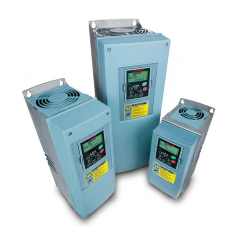
Honeywell NX series User manual

Honeywell

Honeywell NX series User manual

Honeywell Gamewell Velociti AMM-4F User manual

Honeywell

Honeywell Gamewell Velociti AMM-4F User manual

Honeywell PW7K1R1 User manual

Honeywell

Honeywell PW7K1R1 User manual

Honeywell 66 User manual

Honeywell

Honeywell 66 User manual

Honeywell RS-485 User manual

Honeywell

Honeywell RS-485 User manual
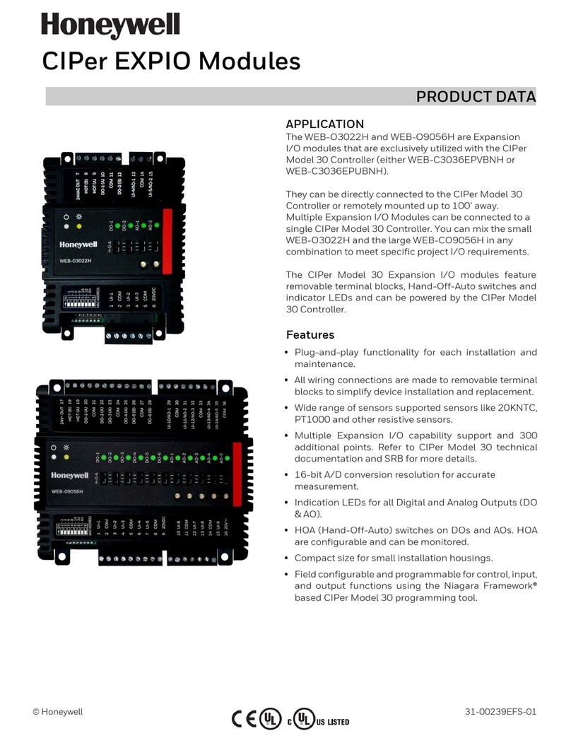
Honeywell PX4ie User manual

Honeywell

Honeywell PX4ie User manual

Popular Computer Hardware manuals by other brands

Advantech PCA-6740 user manual

Advantech

Advantech PCA-6740 user manual

MicroBoards Technology QD-123 user manual

MicroBoards Technology

MicroBoards Technology QD-123 user manual

Gigabyte MC13-LE0 user manual

Gigabyte

Gigabyte MC13-LE0 user manual

EK Pro RTX A5000 Rack user guide

EK

EK Pro RTX A5000 Rack user guide

United Electronic Industries PD2-MF user manual

United Electronic Industries

United Electronic Industries PD2-MF user manual

HighPoint SSD7505 Quick installation guide

HighPoint

HighPoint SSD7505 Quick installation guide

SIIG DP SoundWave 4 Channel PCI Quick installation guide

SIIG

SIIG DP SoundWave 4 Channel PCI Quick installation guide

Imagine communications Selenio BNP 2xr user guide

Imagine communications

Imagine communications Selenio BNP 2xr user guide

Advantech FWA-3033-00A1R Startup manual

Advantech

Advantech FWA-3033-00A1R Startup manual

Advantech MIC-3820 Startup manual

Advantech

Advantech MIC-3820 Startup manual

SIIG IO1037 Quick installation guide

SIIG

SIIG IO1037 Quick installation guide

Brook Universal Fighting Board user guide

Brook

Brook Universal Fighting Board user guide

Sidekick SK-8RG owner's manual

Sidekick

Sidekick SK-8RG owner's manual

Lindy 20960 Installation and use

Lindy

Lindy 20960 Installation and use

Intel RS3FC044 Quick installation user's guide

Intel

Intel RS3FC044 Quick installation user's guide

Abocom WB2000 Quick installation

Abocom

Abocom WB2000 Quick installation

TYAN TS75-B7122 Service engineer's manual

TYAN

TYAN TS75-B7122 Service engineer's manual

GRASS VALLEY 8977AP-4U datasheet

GRASS VALLEY

GRASS VALLEY 8977AP-4U datasheet

manuals.online logo
manuals.online logoBrands
  • About & Mission
  • Contact us
  • Privacy Policy
  • Terms and Conditions

Copyright 2025 Manuals.Online. All Rights Reserved.