manuals.online logo
Brands
  1. Home
  2. •
  3. Brands
  4. •
  5. Honeywell
  6. •
  7. Control Unit
  8. •
  9. Honeywell Notifier FMM-1 User manual

Honeywell Notifier FMM-1 User manual

MOUNTING
The FMM-1 mounts directly to 4-inch square electrical boxes (see Figure 2).
The box must have a minimum depth of 21⁄8inches. Surface mounted electri-
cal boxes (SMB500) are available from Notifier.
FIGURE 2. MODULE MOUNTING:
NOTE: For UL Listed security installations, the FMM-1 must be mounted
within the control panel enclosure.
ISOLATED
QUADRANT
C1066-00
WIRING
NOTE: All wiring must conform to applicable local codes, ordinances, and
regulations. This module is intended for power limited wiring only.
1. Install module wiring in accordance with the job drawings and appropri-
ate wiring diagrams.
2. Set the address on the module per job drawings.
3. Secure module to electrical box (supplied by installer), as shown in
Figure 2.
SPECIFICATIONS
Normal Operating Voltage: 15 to 32 VDC
Maximum Current Draw: 5.0 mA (LED on)
Average Operating Current: 375 µA (group poll); 350 µA (direct poll); 600 µA Max. (Communicating, IDC Shorted)
EOL Resistance: 47K Ohms
Maximum IDC Wiring Resistance: 1,500 Ohms
Maximum IDC Voltage: 11 Volts
Maximum IDC Current: 450µA
Temperature Range: 32°F to 120°F (0°C to 49°C)
Humidity: 10% to 93% Non-condensing
Dimensions: 41⁄2˝ H x 4˝ W x 1
1⁄4˝ D (Mounts to a 4˝ square by 21⁄8˝ deep box.)
Accessories: SMB500 Electrical Box
BEFORE INSTALLING
This information is included as a quick reference installation guide. Refer to
the control panel installation manual for detailed system information. If the
modules will be installed in an existing operational system, inform the opera-
tor and local authority that the system will be temporarily out of service. Dis-
connect power to the control panel before installing the modules.
NOTICE: This manual should be left with the owner/user of this equipment.
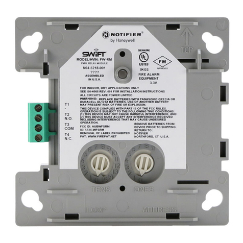
GENERAL DESCRIPTION
The FMM-1 Monitor Module is intended for use in intelligent, two-wire sys-
tems, where the individual address of each module is selected using the built-
in rotary switches. It provides either a 2-wire or 4-wire fault tolerant initiating
device circuit (IDC) for normally open contact fire alarm and supervisory de-
vices, or either normally open or normally closed security devices. The mod-
ule has a panel controlled LED indicator. The FMM-1 can be used to replace
an MMX-1 module in existing systems. FMM-1 is also UL Listed as a com-
mercial proprietary burglar alarm accessory and a commercial central station
burglar alarm accessory.
COMPATIBILITY REQUIREMENTS
To ensure proper operation, this module shall be connected to a compatible
Notifier system control panel (list available from Notifier).
FIGURE 1. CONTROLS AND INDICATORS:
C1067-00
NO-460-010 1 I56-3506-001
FMM-1 Monitor Module
I56-3506-001
INSTALLATION AND MAINTENANCE INSTRUCTIONS
12 Clintonville Road
Northford, CT 06472-1653
Phone: 203.484.7161
FIGURE 3. TYPICAL 2-WIRE INITIATING CIRCUIT CONFIGURATION, NFPA STYLE B OR SECURITY SYSTEMS:
NOTE: For UL Listed security installations, the FMM-1 must be mounted within the control panel enclosure.
(+)
(–)
(+)
(–)
(+)
(–)
MONITOR
MODULE
ANY NUMBER OF UL LISTED CONTACT
CLOSURE DEVICES MAY BE USED. DO NOT MIX
FIRE ALARM INTIATING, SUPERVISORY, OR
SECURITY DEVICES ON THE SAME MODULE.
TO NEXT
DEVICE
FROM PANEL OR
PREVIOUS DEVICE
47K EOL
RESISTOR
ELR-47K
CONNECT MODULES TO LISTED COMPATIBLE
CONTROL PANELS ONLY
SIGNAL LINE CIRCUIT (SLC)
32 VDC MAX.
TWISTED PAIR
IS RECOMENDED
ALL WIRING SHOWN IS SUPERVISED AND POWER LIMITED
INITIATING DEVICE CIRCUIT (IDC) - NFPA STYLE B
POWER LIMITED: 450µA MAX. @ 11 VDC MAX
INSTALL CONTACT CLOSURE DEVICES PER
MANUFACTURER’S INSTALLATION INSTRUCTIONS.
C0918-00
FIGURE 4. TYPICAL 4-WIRE FAULT TOLERANT INITIATING CIRCUIT CONFIGURATION, NFPA STYLE D:
(+)
(-)
(+)
(–)
(+)
(–)
TO NEXT
DEVICE
ANY NUMBER OF UL LISTED CONTACT
CLOSURE DEVICES MAY BE USED. DO NOT MIX
FIRE ALARM INTIATING, SUPERVISORY, OR
SECURITY DEVICES ON THE SAME MODULE.
MONITOR
MODULE
FROM PANEL OR
PREVIOUS DEVICE
CONNECT MODULES TO LISTED COMPATIBLE
CONTROL PANELS ONLY
SIGNAL LINE CIRCUIT (SLC)
32 VDC MAX.
TWISTED PAIR
IS RECOMENDED
ALL WIRING SHOWN IS SUPERVISED AND POWER LIMITED
INSTALL CONTACT CLOSURE DEVICES PER
MANUFACTURER’S INSTALLATION INSTRUCTIONS.
EOL RESISTOR IS
INTERNAL AT
TERMINALS 8 & 9
C0919-02
NO-460-010 2 I56-3506-001
©2007 Notifier

Other Honeywell Control Unit manuals

Honeywell VRN Series User manual

Honeywell

Honeywell VRN Series User manual

Honeywell MasterLogic 50 Series User manual

Honeywell

Honeywell MasterLogic 50 Series User manual

Honeywell SM152 Series User manual

Honeywell

Honeywell SM152 Series User manual

Honeywell GSMVLP5 Assembly instructions

Honeywell

Honeywell GSMVLP5 Assembly instructions

Honeywell DirectLine DL423 User manual

Honeywell

Honeywell DirectLine DL423 User manual

Honeywell T7560A User manual

Honeywell

Honeywell T7560A User manual

Honeywell TR80 Installation guide

Honeywell

Honeywell TR80 Installation guide

Honeywell PM7600B User manual

Honeywell

Honeywell PM7600B User manual

Honeywell TC Series Manual

Honeywell

Honeywell TC Series Manual

Honeywell VHL120 Guide

Honeywell

Honeywell VHL120 Guide

Honeywell RF CM61NG User manual

Honeywell

Honeywell RF CM61NG User manual

Honeywell Braukmann DR300 User manual

Honeywell

Honeywell Braukmann DR300 User manual

Honeywell NOTIFIER M700 Series User manual

Honeywell

Honeywell NOTIFIER M700 Series User manual

Honeywell 7800 SERIES User manual

Honeywell

Honeywell 7800 SERIES User manual

Honeywell VS8420C User manual

Honeywell

Honeywell VS8420C User manual

Honeywell R4140G User manual

Honeywell

Honeywell R4140G User manual

Honeywell Braukmann FD300 User manual

Honeywell

Honeywell Braukmann FD300 User manual

Honeywell Exi-/MaxLED T2 User manual

Honeywell

Honeywell Exi-/MaxLED T2 User manual

Honeywell VRW2 User manual

Honeywell

Honeywell VRW2 User manual

Honeywell PS300 User manual

Honeywell

Honeywell PS300 User manual

Honeywell V5097A-E Operation manual

Honeywell

Honeywell V5097A-E Operation manual

Honeywell Kromschroder TC 1 User manual

Honeywell

Honeywell Kromschroder TC 1 User manual

Honeywell Krom Schroder BCU 580 Manual

Honeywell

Honeywell Krom Schroder BCU 580 Manual

Honeywell LCBS Connect User manual

Honeywell

Honeywell LCBS Connect User manual

Popular Control Unit manuals by other brands

Nevco MPCX2 Football Operator instructions

Nevco

Nevco MPCX2 Football Operator instructions

IEI Technology PulM Series Quick installation guide

IEI Technology

IEI Technology PulM Series Quick installation guide

HOLOVISION 101 Installation instructions manual

HOLOVISION

HOLOVISION 101 Installation instructions manual

STERIFLOW I&M MK901 Series Installation & maintenance instructions

STERIFLOW

STERIFLOW I&M MK901 Series Installation & maintenance instructions

Atmel AT89RFD-08 user guide

Atmel

Atmel AT89RFD-08 user guide

Ebyte E78-400M22S user manual

Ebyte

Ebyte E78-400M22S user manual

Behringer 130 DUAL VCA quick start guide

Behringer

Behringer 130 DUAL VCA quick start guide

Erica Synths OUTPUT Guide to Assembly & Usage

Erica Synths

Erica Synths OUTPUT Guide to Assembly & Usage

Omron CQM1-SRM21-V1 quick start guide

Omron

Omron CQM1-SRM21-V1 quick start guide

Quectel BC66-NA manual

Quectel

Quectel BC66-NA manual

Siemens 7KM9300-0AE01-0AA0 operating instructions

Siemens

Siemens 7KM9300-0AE01-0AA0 operating instructions

Feig Electronic OBID i-scan ID ISC.M02 Montage, installation

Feig Electronic

Feig Electronic OBID i-scan ID ISC.M02 Montage, installation

SOMFY Control Box 3S io user manual

SOMFY

SOMFY Control Box 3S io user manual

Unitronics IO-LC1 manual

Unitronics

Unitronics IO-LC1 manual

Siemens SIMATIC ET 200SP IM 155-6 PN/2 HF manual

Siemens

Siemens SIMATIC ET 200SP IM 155-6 PN/2 HF manual

Festo CPX-E-4IOL operating instructions

Festo

Festo CPX-E-4IOL operating instructions

Pilz PNOZ mc12p operating manual

Pilz

Pilz PNOZ mc12p operating manual

Omron EJ1 EtherCAT user manual

Omron

Omron EJ1 EtherCAT user manual

manuals.online logo
manuals.online logoBrands
  • About & Mission
  • Contact us
  • Privacy Policy
  • Terms and Conditions

Copyright 2025 Manuals.Online. All Rights Reserved.