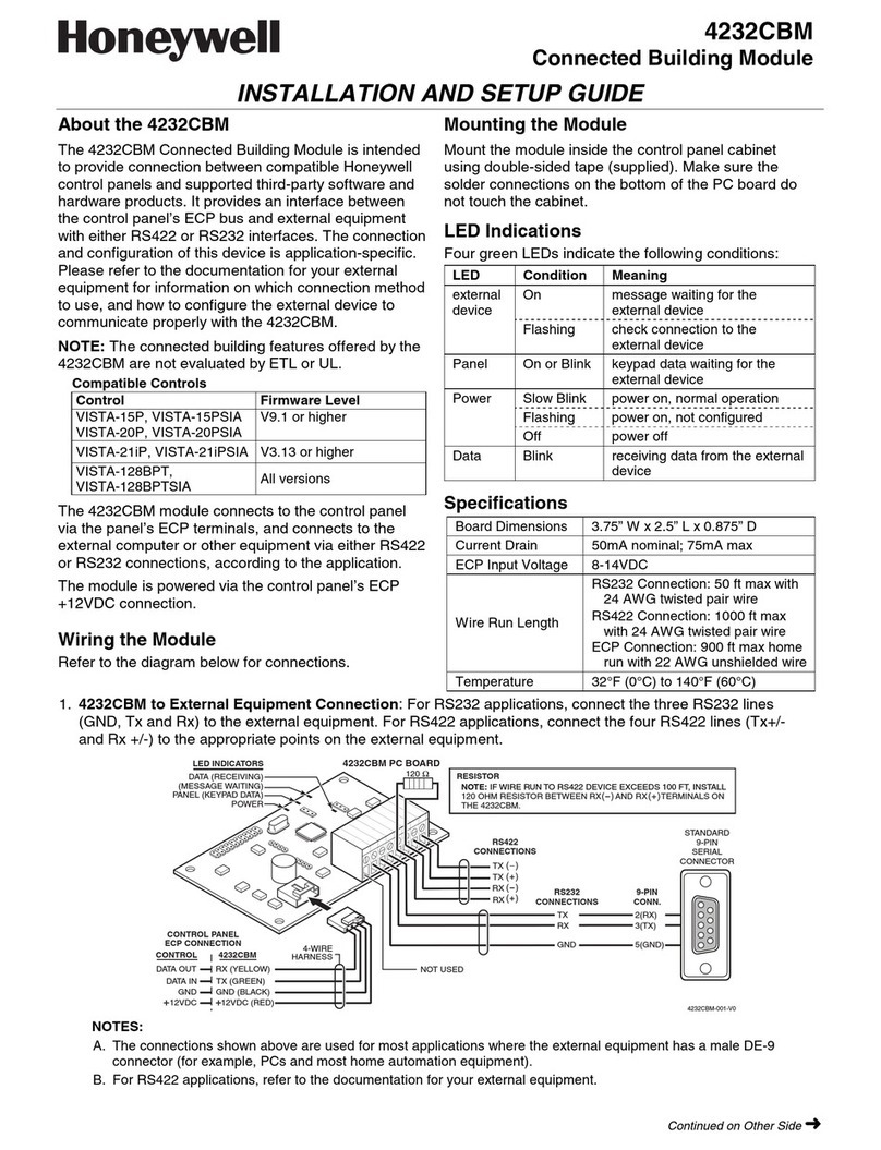
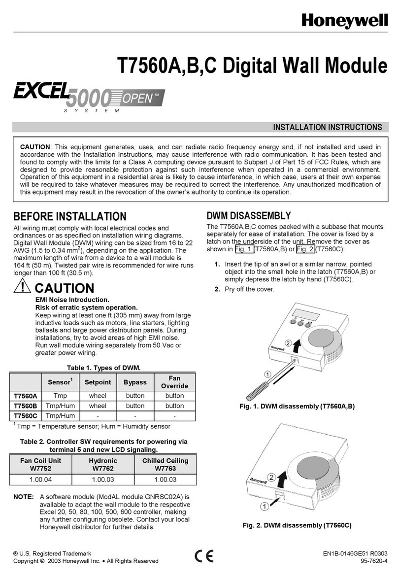
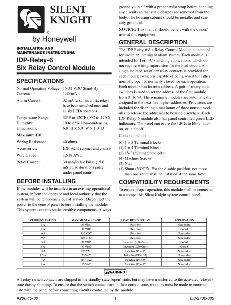
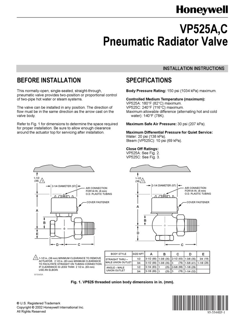
manuals.online logo
Brands
  1. Home
  2. •
  3. Brands
  4. •
  5. Honeywell
  6. •
  7. Control Unit
  8. •
  9. Honeywell RM7838A Manual

Honeywell RM7838A Manual

ConversionWiring Diagrams
for RM7838A
B. M. • 7-92 • © Honeywell Inc. 1992 • Form Number 65-0129
The diagrams and instructions contained in this booklet are for converting the following model
semi-automatic controls to RM7838 microprocessor based integrated burner control.
TABLE OF CONTENTS Page
Product Section Matrix ..................................................................................................................................................... 3
Section I.............................................................................................................................................................................. 5
R4138A,B,C,D
Section II ............................................................................................................................................................................ 6
Honeywell W124
Section III........................................................................................................................................................................... 8
Fireye 26SJ5 6000, 6052, 6152
WARNING
Improper configuration jumper selection could cause a fire or explosion hazard that could lead to property
damage, severe injury or death.
CAUTION
1. Installer must be a trained, experienced, flame safeguard control service technician.
2. Disconnect power supply before beginning installation to prevent electrical shock and equipment damage. More
than one power supply disconnect may be involved.
3. All wiring must comply with applicable local electrical codes, ordinances, and regulations.
4. All line voltage terminal wiring shall be no. 14, 16 or 18 copper conductor TTW (60C) or THW (75C) or THHN
(90C) 600 volt insulation wire. A maximum of two conductors can be wired to each Q7800 Subbase terminal.
5. Voltage and frequency of the power supply and flame detector(s) connected to this control must agree with those
marked on the device.
6. Loads connected to the control terminals must not exceed ratings listed in the Specification, form 65-0108, or on
the RM7838A label.
7. Allexternaltimersmustbelistedorcomponentrecognizedbyauthoritieshavingjurisdictionforthespecificpurpose
for which they are used.
8. Perform all required checkout tests after installation is complete.
2
IMPORTANT:
1. For on-off gas-fired systems, some authorities having
jurisdiction prohibit the wiring of any limit or operat-
ing contacts in series between the flame safeguard
control and the main fuel valve(s).
2. Do not connect more than two C7012E,F or
C7076A,D Ultraviolet Flame Detectors (with self-
checking shutter) in parallel to the same terminals.
3. This equipment generates, uses and can radiate radio
frequency energy, and if not installed and used in
accordance with the instructions, may cause interfer-
ence to radio communications. It has been tested and
foundtocomplywiththelimitsforaClassBcomputing
device of Part 15 of FCC rules, which are designed to
provide reasonable protection against such interfer-
ence when operated in a commercial environment.
Operation of this equipment in a residential area may
cause interference, in which case, users at their own
expense may be required to take whatever measures
are required to correct this interference.
4. This digital apparatus does not exceed the Class B
limitsforradionoisefordigitalapparatussetoutinthe
Radio Interference Regulations of the Canadian De-
partment of Communications.
NORMAL OPERATION:
Pilot Flame
Establishing Period
Device Initiate Standby Purge (PFEP) Run
RM7838A 10 sec. * ** 4 or 10 sec. *
* STANDBY and RUN can be an infinite time period.
** PURGE will be determined by which ST7800A Purge Card is selected.
APPROVAL BODIES:
Underwriters Laboratories Inc. listed, File No. MP268,
Guide No. MCCZ.
Canadian Standards Association certified, LR9S329-3.
Factory Mutual approved, Report No. JI1V9A0.AF.
Industrial Risk Insurers acceptable.
Federal Communications Commission, Part 15, Class B.
Canadian Department of Communications, CS-03,
Certification No. 5733459A.
MOUNTING:Q7800A forpanel mountor Q7800Bfor wall
or burner mount.
REQUIRED COMPONENTS:
Q7800 Subbase
ST7800 Purge Timer
RM7847/48/49/86 Flame Amplifier
ACCESSORIES:
5-Wire Connector
—part no. 203541.
Combustion Service Manager
—part no. ZM7850A1001.
Communication Interface Base Unit
—part no. Q7700A1014.
Communication Interface ControlBus Module
—part no. QS7800A1001.
DATA CONTROLBUS MODULE™
—part no. S7810A1009.
Electrical Access Slot Cover
—part no. 203765.
Expanded Annunciator
—part no. S7830A1005
Flame Simulators
—part no. 203659 UV Flame Simulator.
—part no. 123514A Rectification Simulator.
Remote Display Mounting Bracket
—part no. 203765.
Tester
—part no. A7800A1002.
Remote Display Power Supply
—part no. 203968 Plug-in.
3 65-0129
PRODUCT SELECTION MATRIX
SEMI-AUTOMATIC ON - OFF BURNER CONTROL
SELECT A RELAY
MODULE
SELECT A
SUBBASE
1.)
2.)
SELECT A
PURGE CARD
3.)
SELECT A FLAME
AMPLIFIER
4.)
SELECT
OPTIONS
5.)
M5157A
1 120 VAC.
2 FFRT = FLAME FAILURE RESPONSE TIME.
3 ONE Q7700 WILL SUPPORT ANY COMBINATION OF UP TO SIX (6) QS7700s/QS7800s.
1
EXPANDED ANNUNCIATION
S7830A1005 EXPANDED ANNUNCIATOR
REMOTE DISPLAY MOUNTING
203765 REMOTE MOUNTING BRACKET
221818A SIX FEET EXTENSION CABLE ASSEMBLY
13 VDC POWER SUPPLY
• 203968A PLUG-IN
RM7838A1006 WITH DISPLAY 50 HZ
RM7838A1014 WITH DISPLAY 60 HZ
Q7800A1005 PANEL MOUNT OR
Q7800B1003 BURNER/WALL
MOUNT
ST7800A1005 2 SEC.
ST7800A1013 7 SEC.
ST7800A1021 10 SEC.
ST7800A1039 30 SEC.
ST7800A1047 40 SEC.
ST7800A1054 60 SEC.
ST7800A1062 90 SEC.
ST7800A1070 2.5 MIN.
ST7800A1088 4 MIN.
ST7800A1096 6 MIN.
ST7800A1104 9 MIN.
ST7800A1112 12 MIN.
ST7800A1120 15 MIN.
ST7800A1138 22 MIN.
ST7800A1146 30 MIN.
R7847A1025 0.8 Sec. FFRT (RECTIFICATION). USE
 W/FLAME RODS OR PHOTOCELLS.
R7847A1033 3.0 Sec. FFRT (RECTIFICATION). USE
 W/FLAME RODS, PHOTOCELLS OR 
 C7012A,C.
R7847B1023 0.8 Sec. FFRT (RECTICATION). USE 
 W/FLAME RODS OR PHOTOCELLS.
R7847B1031 3.0 Sec. FFRT (RECTICATION). USE 
 W/FLAME RODS, PHOTOCELLS OR 
 C7012A,C.
R7847C1005 3.0 Sec. FFRT (C7012E,F)
R7848A1008 3.0 Sec. FFRT (C7015)
R7848B1006 3.0 Sec. FFRT (C7015)
R7849A1015 0.8 Sec. FFRT (C7027/C7035/C7044)
R7849A1023 3.0 Sec. FFRT (C7027/C7035/C7044)
R7849B1013 0.8 Sec. FFRT (C7027/C7035/C7044)
R7849B1021 3.0 Sec. FFRT (C7027/C7035/C7044)
R7886A1001 3.0 Sec. FFRT (C7076A,D)
COMMUNICATIONS
Q7700A1014 BASE UNIT
QS7800A1001 CONTROLBUS MODULE
ZM7850A1001 COMBUSTION SYSTEM MANAGER™
REMOTE DISPLAY MODULE
S7800A1001 DISPLAY MODULE
2
3
4
DIRECTIONS:
1. Disconnect all power to control being replaced. Note
that more than one power supply disconnect may be
involved.
2. Remove old control from subbase.
3. Mark all wires on subbase; i.e., wires connected to
terminal 1 should be marked 1.
4. Disconnect wires from subbase.
5. Remove old subbase.
6. Mount Q7800 Subbase.
7. Connect wires to subbase according to wiring conver-
sion for control being replaced. Pay close attention to
footnotes.Thetrianglesymbol
withanumberorletter
inside designates a footnote.
8. Install the RM7838A control. Make sure the proper
ST7800 purge card and flame detector have been se-
lected for the application.
9. TheRM7838Ahasone siteconfigurablejumperoption
thatisusedtoselectthePilotFlameEstablishingPeriod.
Refer to the RM7838A instructions, form 60-0108, for
assistance and proper selection.
10. Refer to the RM7838A instructions, form 60-0108, for
checkout and start-up.
GENERAL FOOTNOTES:
1 Be sure system is modernized to 120 Vac. The
replacement 7800 SERIES control is 120 Vac.
2 Select subbase.
3 TheRM7838Acannotbewiredforredundantappli-
cations without external relay logic to isolate the
safety critical loads test of the RM7838.
4 Select proper prepurge card based on the purge
timing of the control being replaced or the external
purge timer.
5 Select proper flame amplifier according to the
cross reference table or to meet the needs of the
application.
6 Selectproperflamedetectorwhenconvertingfroma
competitive control to Honeywell or if a different
flame detection system is desired; i.e., the old flame
amplifier was flame rectification and the new flame
amplifier is to be ultraviolet. Refer to the product
selection matrix on page 3 to select proper flame
detector.
7 Proper grounding of the green subbase terminal
screw to an electrical earth ground is a MUST for
proper operation of the 7800 SERIES control.
8 NOTE: UL allows only two electrical wires to each
subbase terminal. Wiring information may show
more than two wires to a particular terminal, which
mayrequireanexternalconnectiontoaccomplishthe
termination.
9 Selectpropersiteconfigurablejumperconfiguration
as required by the application. Refer to the cross
reference table and to Specifications, form 65-0108.
NOTE: Jumper number 1 selects Pilot Flame
Establishing Period.
10 Donotuse anyunusedsubbaseterminals asawiring
junction or termination point.
1
5 65-0129
7800 SERIES CONVERSION WIRING DIAGRAM
FROM R4138A, B, C, D
(DEVICE TO BE MODERNIZED)
M3307
RM7838A
(O.S. NUMBER OF RELAY MODULE TO BE USED)
TO
12
Q7800
13
14
15
16
18
17
19
20
21
22
G
L2
9
8
7
6
5
4
3
10
F
G
C
E
F
F
1253 784
D
GENERAL FOOTNOTES, SEE PAGE 4.
2
10
9
8
A
(L1)
B
20
6
18
12
6
L2
7, 17
8
19
R4138B,D DEVICES PROVIDED CIRCUITRY TO
WITHSTAND UP TO A ONE SECOND POWER
INTERRUPTION WITHOUT SYSTEM SHUTDOWN.
THE REPLACEMENT 7800 SERIES CONTROL WILL
RETURN TO INITIATE AND THE SYSTEM WILL NEED
TO BE RESTARTED BEGINNING WITH PURGE.
DISREGARD R4138 SUBBASE JUMPERS (IF USED);
13–14, 12–F, AND L1–6. THESE JUMPERS ARE NOT
REQUIRED FOR THE RM7838 CONTROL.
IF THE R4138 HAS AN ALARM SILENCING
RELAY, CONNECT THE R4138 SUBBASE
TERMINAL 15 TO Q7800 TERMINAL 3.
LOCATE L1 CONNECTION TO ALARM
SILENCING RELAY AND WIRE NUT THIS
LEADWIRTE WITH THE ALARM LEADWIRE
THAT IS CONNECTED TO THE R4138
SUBBASE TERMINAL 16.
IF THERE IS NO SILENCING RELAY,
CONNECT THE R4138 SUBBASE TERMINAL
16 TO THE Q7800 SUBBASE TERMINAL 3
AND IGNORE THE JUMPER FROM THE
R4138 SUBBASE TERMINALS 11–15.
IF A JUMPER WAS INSTALLED BETWEEN
THE R4138 SUBBASE TERMINALS 7–13,
REMOVE AND DISCARD THIS JUMPER.
THE R4138 SUBBASE TERMINAL L1 WAS
POWERED FROM THE MASTER SWITCH
THROUGH LIMITS AND RUNNING
INTERLOCKS. THE RM7838 SUBBASE L1
TERMINAL (4) MUST BE POWERED
DIRECTLY FROM THE MASTER SWITCH.
CONNECT THE SERIES STRING OF THE
BURNER SWITCH, LIMITS AND RUNNING
INTERLOCKS (IF USED) BETWEEN THE
MASTER SWITCH AND TERMINAL 7.
A
B
C
D
E
F
6
7800 SERIES CONVERSION WIRING DIAGRAM
FROM___________________ TO ________________________
(DEVICE TO BE MODERNIZED) (O.S. NUMBER OF RELAY MODULE TO BE USED)
12
Q7800
13
14
15
16
18
17
19
20
21
22
G
L2
9
8
7
6
5
4
3
10
F
G
L2
L1
3
E
W124 RM7838A
M2669
12568
347
B
C
GENERAL FOOTNOTES, SEE PAGE 4.
10
9
7
210
8
D
F
6
G
H
5
A
(L1)
(Specific Instructions on page 7)
765-0129
Specific instructions and footnotes for converting from
the Honeywell W124 Protectoglo Flame Safeguard to the
RM7838A. The footnotes will be designated with a letter in
a triangle (i.e.,
A
) for specific footnotes or a number in a
triangle (i.e.,
1
) for general footnotes from page 4.
1. Thefollowingcomponentswillbeneededinaddition
to the 7800 SERIES control.
• S445A Start-Stop Switch.
• Doublepole/singlethrowswitch(ifalarmsilenc-
ing is desired).
2. Wires that can be moved from the W124 subbase
terminals to the RM7838A subbase terminals are
shown in the tabs.
3. Locate, label and disconnect the hot supply wire
for the:
• alarm
• ignition transformer.
4. Remove and discard the following:
• Start/stop Switch (if it is not a S445A Start-Stop
Switch).
• Temperaturecontroller(ifused).Noteiftherewas
a temperature controller, a line voltage tempera-
ture controller will have to be installed in series
with the burner control switch.
• Jumper wires (if used) that are between W124
terminals 2-11, 3-8, 4-9, L1-11, R-W-B, or
W-10.
• Any external purge timer (if used).
5. Connect the hot supply wire of the ignition trans-
former to terminal C of the S445 Start-
Stop Switch.
6. Note General Footnotes.
SPECIFIC FOOTNOTES:
A Install the High Fire Purge switch between Q7800
Subbase terminals 7 and 19. If no High Fire
Purge Switch is used then install a jumper wire
between Q7800 subbase terminals 7 and 14. Note
installing the jumper will add 30 seconds to the
purge timing.
B Connectthehotsupplywireofthealarmthroughone
pole of the double pole/single throw alarm silencing
switch (if used) to Q7800 Subbase terminal 3.
C ConnectterminalBofthe S445A Start-Stop Switch
through the other pole of the double pole/single
throw alarm silencing switch (if used) to Q7800
Subbase terminal 6.
D Connectthelimitsofrunninginterlocks(HighLimit,
Pressure Switch, Combustion Air Switch and etc.)
in series with the burner switch and temperature
controller (if used). Connect this series string be-
tween L1 of the master switch and Q7800 Subbase
terminal 7.
F ConnecttheLowFirePurgeSwitch and any starting
interlocksinseriesbetweenQ7800Subbaseterminal
10 and terminal D of the S445 Start-Stop Switch.
G ConnectQ7800Subbaseterminal21toterminalAof
the S445 Start-Stop Switch.
H If Dynamic Self Check has been selected for the
flameamplifier,thenconnectoneoftheshutterleads
(white)oftheC7012E,ForC7076A,DFlameDetec-
tor to Q7800 Subbase terminal 22.
7800 SERIES CONVERSION WIRING DIAGRAM
FROM FIREYE 26SJ5 6000, 6052,6152
(DEVICE TO BE MODERNIZED)
M3306
RM7838A
(O.S. NUMBER OF RELAY MODULE TO BE USED)
TO
12
Q7800
13
14
15
16
18
17
19
20
21
22
G
L2
9
8
7
6
5
4
3
10
F
15
2
C
4
3
E
F
1253 784
A
D
GENERAL FOOTNOTES, SEE PAGE 4.
1
2
10
9
8
10
(L1)
B
GH
J
56
1314
6
7
8
(Specific Instructions on page 9)
SPECIFIC FOOTNOTES:
AIf the neutral wire is on terminal 1 of the 26SJ5
control, then the system is 208 Vac or 240 Vac. The
systemwillhavetoberecontrolledto120 Vactouse
the 7800 SERIES control.
BInstall the High Fire Purge switch between Q7800
Subbase terminals 7 and 19. If no High Fire Purge
switch is used, then install a jumper between Q7800
Subbase terminals 7 and 19. Note that installing a
jumper will add 30 seconds to the purge timing.
CConnectthehotsupplywireofthealarmthroughone
pole of the double pole/single throw alarm silencing
switch (if used) to Q7800 Subbase terminal 3.
D Connect terminal B of the S445A Start-Stop Switch
through the other pole of the double pole/single
throw alarm silencing switch (if used) to Q7800
Subbase terminal 6.
EConnect the hot supply wire of the Pilot Fuel Valve
to Q7800 Subbase terminal 8.
FConnect the hot supply wire of the Main Fuel Valve
to Q7800 Subbase terminal 9.
GConnect the starting interlocks and Low Fire Purge
SwitchinseriesbetweenQ7800Subbaseterminal10
and terminal D of the S445 Start-Stop Switch.
HConnectQ7800Subbaseterminal21toterminalAof
the S445 Start-Stop Switch.
J If Dynamic Self Check has been selected for the
flameamplifier,thenconnectoneoftheshutterleads
(white)oftheC7012E,ForC7076A,DFlameDetec-
tor to Q7800 Subbase terminal 22.
9
Specific instructions and footnotes for converting from
the Fireye 26SJ56000, 6052, 6152 to the RM7838A. The
footnotes will be designated with a letter in a triangle
(i.e.,
A
) for specific footnotes or a number in a triangle
(i.e.,
1
) for general footnotes from page 4.
1. Thefollowingcomponentswillbeneededinaddition
to the 7800 SERIES control.
• S445A Start-Stop Switch.
• Double pole/single throw switch (if alarm
silencing is desired).
2. Locate, label and disconnect the hot supply (120 V
supply) wire for the:
• Alarm
• Ignition Transformer
• Main Fuel Valve
• Pilot Valve
3. Remove and discard the following:
• Alarm Silencing Switch (if used).
• Start Switch.
• Purge Timer (TA).
• Main Flame Timer (TB).
• Pilot Timer (TC).
• Purging Indicator Lamp.
• Flame OFF Indicator Lamp.
• Flame ON Indicator Lamp.
• Leadwires that are on terminals 5, 7, 8, 9, 10, 11,
12, A, C and L.
4. Note General Footnotes.
5. Wires that can be moved from the Fireye 26SJ5
terminals to the RM7838A terminals are shown in
the tabs.
6. Connect the hot supply wire of the ignition trans-
former to terminal C of the S445 Start-Stop Switch.
7. If there was an auxiliary load on terminal 6 of the
26SJ5device,then connectthisloadto terminalBof
theS445Start-StopSwitch.Notethatifthecombined
loadoftheignitiontransformerandtheauxiliaryload
is greater than 4.5A, then an external relay will have
to be used to switch the auxiliary load. Connect the
relay coil (120 Vac) to terminal B of the S445 Start-
Stop Switch.
Printed in U.S.A.
Home and Building ControlHome and Building Control
Honeywell Inc. Honeywell Limited—Honeywell Limitée
1985 Douglas Drive North 740 Ellesmere Road
Golden Valley, Minnesota 55422 Scarborough, Ontario
M1P 2V9

Other Honeywell Control Unit manuals

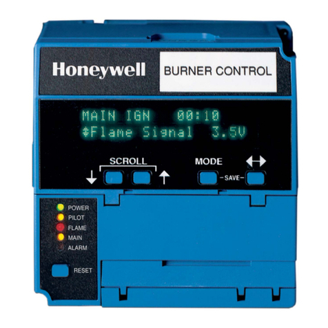
Honeywell SILENT KNIGHT SK-FML User manual

Honeywell

Honeywell SILENT KNIGHT SK-FML User manual

Honeywell satronic DMG 971 Instructions for use

Honeywell

Honeywell satronic DMG 971 Instructions for use

Honeywell S8600A User manual

Honeywell

Honeywell S8600A User manual

Honeywell NOTIFIER XP10-M User manual

Honeywell

Honeywell NOTIFIER XP10-M User manual

Honeywell ADEMCO 4100SM Assembly instructions

Honeywell

Honeywell ADEMCO 4100SM Assembly instructions

Honeywell V-Plex ADEMCO 4297 Assembly instructions

Honeywell

Honeywell V-Plex ADEMCO 4297 Assembly instructions

Honeywell SM180 User manual

Honeywell

Honeywell SM180 User manual

Honeywell DCCC6500 User manual

Honeywell

Honeywell DCCC6500 User manual

Honeywell V5004TF User manual

Honeywell

Honeywell V5004TF User manual

Honeywell MK VI Manual

Honeywell

Honeywell MK VI Manual

Honeywell SOMAT39 User manual

Honeywell

Honeywell SOMAT39 User manual

Honeywell FF-SRE6029 User manual

Honeywell

Honeywell FF-SRE6029 User manual

Honeywell VS8510 User manual

Honeywell

Honeywell VS8510 User manual

Honeywell Class 500 User manual

Honeywell

Honeywell Class 500 User manual

Honeywell Maxon SMA11 User manual

Honeywell

Honeywell Maxon SMA11 User manual

Honeywell ADEMCO VA8201 Assembly instructions

Honeywell

Honeywell ADEMCO VA8201 Assembly instructions

Honeywell Pro-Watch 7000 User manual

Honeywell

Honeywell Pro-Watch 7000 User manual

Honeywell GSMVLP4G Installation guide

Honeywell

Honeywell GSMVLP4G Installation guide

Honeywell ESSER IQ8MCP User manual

Honeywell

Honeywell ESSER IQ8MCP User manual

Honeywell BSM Assembly instructions

Honeywell

Honeywell BSM Assembly instructions

Honeywell VQ400 Series User manual

Honeywell

Honeywell VQ400 Series User manual

Honeywell S7800A1001 User manual

Honeywell

Honeywell S7800A1001 User manual

Honeywell VS8420 User manual

Honeywell

Honeywell VS8420 User manual

Honeywell ADEMCO 4204 User manual

Honeywell

Honeywell ADEMCO 4204 User manual

Popular Control Unit manuals by other brands

Nevco MPCX2 Football Operator instructions

Nevco

Nevco MPCX2 Football Operator instructions

IEI Technology PulM Series Quick installation guide

IEI Technology

IEI Technology PulM Series Quick installation guide

HOLOVISION 101 Installation instructions manual

HOLOVISION

HOLOVISION 101 Installation instructions manual

STERIFLOW I&M MK901 Series Installation & maintenance instructions

STERIFLOW

STERIFLOW I&M MK901 Series Installation & maintenance instructions

Atmel AT89RFD-08 user guide

Atmel

Atmel AT89RFD-08 user guide

Ebyte E78-400M22S user manual

Ebyte

Ebyte E78-400M22S user manual

Behringer 130 DUAL VCA quick start guide

Behringer

Behringer 130 DUAL VCA quick start guide

Erica Synths OUTPUT Guide to Assembly & Usage

Erica Synths

Erica Synths OUTPUT Guide to Assembly & Usage

Omron CQM1-SRM21-V1 quick start guide

Omron

Omron CQM1-SRM21-V1 quick start guide

Quectel BC66-NA manual

Quectel

Quectel BC66-NA manual

Siemens 7KM9300-0AE01-0AA0 operating instructions

Siemens

Siemens 7KM9300-0AE01-0AA0 operating instructions

Feig Electronic OBID i-scan ID ISC.M02 Montage, installation

Feig Electronic

Feig Electronic OBID i-scan ID ISC.M02 Montage, installation

SOMFY Control Box 3S io user manual

SOMFY

SOMFY Control Box 3S io user manual

Unitronics IO-LC1 manual

Unitronics

Unitronics IO-LC1 manual

Siemens SIMATIC ET 200SP IM 155-6 PN/2 HF manual

Siemens

Siemens SIMATIC ET 200SP IM 155-6 PN/2 HF manual

Festo CPX-E-4IOL operating instructions

Festo

Festo CPX-E-4IOL operating instructions

Pilz PNOZ mc12p operating manual

Pilz

Pilz PNOZ mc12p operating manual

Omron EJ1 EtherCAT user manual

Omron

Omron EJ1 EtherCAT user manual

manuals.online logo
manuals.online logoBrands
  • About & Mission
  • Contact us
  • Privacy Policy
  • Terms and Conditions

Copyright 2025 Manuals.Online. All Rights Reserved.