manuals.online logo
Brands
  1. Home
  2. •
  3. Brands
  4. •
  5. Festo
  6. •
  7. Control Unit
  8. •
  9. Festo CPX-E-4IOL User manual

Festo CPX-E-4IOL User manual

Translation of the original instructions
© 2020 all rights reserved to Festo SE & Co. KG
IO-Link® is a registered trademark of its respective trademark holder in certain
countries.
1 About this document
This document describes the use of the above-mentioned product.
Certain aspects of use are described in other documents and must be observed
è 1.1 Further applicable documents.
1.1 Further applicable documents
All available documents for the product èwww.festo.com/pk.
Document Contents
Description of automation system CPX-E
(CPX-E-SYS)
Detailed description of automation system CPX-E
Instruction manual forautomation system CPX-E
(CPX-E-SYS)
Instruction manual and important information on
assembly, electrical installation and mainten-
ance tasks for an automation system CPX-E
Description of IO-Link master module
CPX-E-4IOL-… (CPX-E-4IOL-…)
Detailed description of product function and
parameterisation options
Documentation of the components in an
automation system CPX-E and the connected
peripherals
Information on using the components
Operating conditions| EX Information on the use of the product in explos-
ive gas atmospheres
Documentation of the connected devices with
the IO-Link interface
Information on commissioning and paramet-
erisation of the components
Documentation for the higher-order controller
and the additional participants in the network
Information on commissioning and paramet-
erisation of the components
Tab. 1 Further applicable documents
1.2 Product version
This document refers to the following product versions:
Product Version
CPX-E-4IOL IO-Link master module CPX-E-4IOL, revision1 or later
CPX-E-4IOL-EX1E1) IO-Link master module CPX-E-4IOL-EX1E, revision1 or later
1) Use in an industrial environment and in process automation according to NE21 and in potentially explos-
ive atmospheres
Tab. 2 Product version
The product version can be identified from the product labelling or with the help
of appropriate software from Festo.
Appropriate software for determining the product version can be found in the
Festo Support Portal èwww.festo.com/sp.
Information on using the software can be found in the integrated Help function.
There may be an updated version of this document for these or later product ver-
sions èwww.festo.com/sp.
1.3 Product labelling
The product labelling is located on the left-hand side of the module. Scanning the
printed Data Matrix Code with an appropriate device opens the Festo Support
Portal, with the information appropriate for the product. Alternatively, the Product
Key (11-digit alphanumeric code on the product labelling) can be entered in the
search field of the Support Portal.
You can find detailed information on the product labelling in the description of the
module è 1.1 Further applicable documents.
1.4 Specified standards
Version status
EN60529:2013-10 IEC60204-1:2014-10
EN61000-6-2:2005-08 NE21:2012-05
EN61000-6-4:2007-01 –
Tab. 3 Standards specified in the document
1.5 UL/CSA Certification
In combination with the UL inspection mark on the product, the information in this
section must also be observed in order to comply with the certification conditions
of Underwriters Laboratories Inc. (UL) for USA and Canada.
UL certification information
Product category code NRAQ/NRAQ7
File number E239998
Considered standards UL 61010-1, 3rd Edition, May 11, 2012, revised April 29, 2016
CAN/CSA-C22.2 No. 61010-1-12, 3rd Edition, revision dated April
29, 2016
UL 61010-2-201, 1st Edition, revised February 20, 2017
CSA-C22.2 No. 61010-2-201: 14, 1st Edition, issue date January
01, 2014
UL mark
Tab. 4 UL/CSA Certification Information
– Technical data and environmental conditions may be subject to change in
order to comply with Underwriters Laboratories Inc. (UL) certification require-
ments for the USA and Canada.
Observe deviations èTechnical data.
– The unit shall be supplied by a power source which fulfils the requirements
on a limited-energy circuit in accordance to IEC/EN/UL/CSA 61010-1 or on a
Limited Power Source (LPS) in accordance to IEC/EN/UL/CSA 60950-1 or
IEC/EN/UL/CSA 62368-1 or a Class 2 circuit in accordance to NEC or CEC.
2 Safety
2.1 Safety instructions
– Take into consideration the legal regulations for the respective destination.
– Use the product only within the defined values
è 14 Technical Dataè Tab. 16 Ambient Conditions UL/CSA.
– Observe labelling on the product.
– Observe further applicable documents.
– Store the product in a cool, dry, UV-protected and corrosion-protected envir-
onment. Ensure that storage times are kept to a minimum.
– Before working on the product: switch off the power supply and secure it
against being switched on again.
– Comply with the handling specifications for electrostatically sensitive devices.
2.2 Intended Use
The product described in this document is intended only for use as an interface
between an Automation system CPX-E and devices with IO-Link interface.
Use the product only as follows:
– Use only in an industrial environment. Outside industrial environments,
e.g.in commercial and residential/mixed-use areas, it may be necessary to
take measures to suppress radio interference.
– Use only in combination with modules and components that are permissible
for the respective product variant èwww.festo.com/catalogue.
– Only use the product if it is in perfect technical condition.
– Only use the product in original status without unauthorised modifications.
Only the conversions or modifications described in this and the further applic-
able documents are permitted.
Additional application ranges for the module CPX-E-…-EX1E:
– Use in process automation
– Use in potentially explosive atmospheres
2.3 Training of Qualified Personnel
Installation, commissioning, maintenance and disassembly should only be con-
ducted by qualified personnel. The qualified personnel must be familiar with
installation of electrical control systems.
3 Further information
– Accessories èwww.festo.com/catalogue.
– Spare parts èwww.festo.com/spareparts.
8126622
CPX-E-4IOL-...
IO-Link master module
8126622
2020-01a
[8126624]
Instructions| Operating
Festo SE & Co. KG
Ruiter Straße 82
73734 Esslingen
Germany
+49 711 347-0
www.festo.com
4 Service
Contact your regional Festo contact person if you have technical questions
èwww.festo.com.
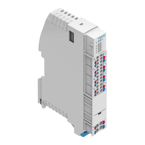
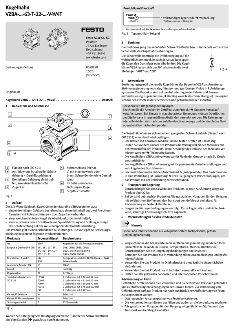
5 Product overview
5.1 Function
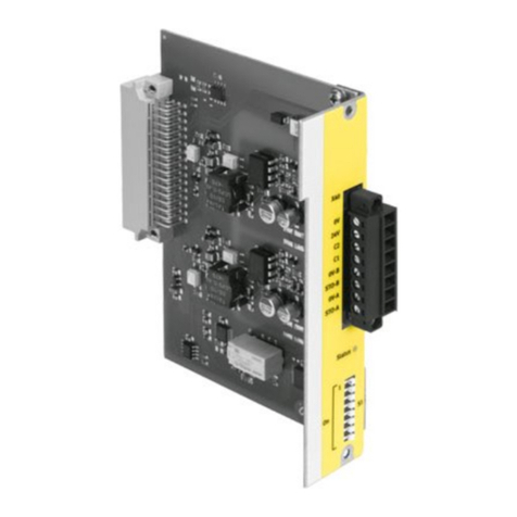
In an Automation system CPX-E, the product provides four IO-Link interfaces
(ports).
5.2 Configuration
5.2.1 Product design
1LED indicators
2Terminal strips of the IO-Link
interfaces (ports 1 ... 4)
[X0] ... [X3]
3Terminal strip of load voltage
supply UOUT [XD]
4Terminal strip interlock
5Linking element
6DIL switch
Fig. 1 Product design
5.2.2 Display components
1Module error [P] (red)
2Standard IO mode (SIO)
[X0] … [X3] (yellow)
3IO-Link mode (IOL)
[X0] … [X3] (green)
4Load voltage supply UOUT [PL]
(green)
Fig. 2 LED indicators
5.2.3 Control elements
The address space (inputs/outputs) provided by the module is set using DIL
switches è Tab. 5 DIL switch.
Switch position combinations that are not listed lead to an error (error number
204).
DIL switch Address space [byte]
1 2 3 4 5 6…8 Per port Module
OFF OFF OFF OFF OFF OFF 2 E/2 A1) 8 E/8 A1)
ON OFF OFF OFF OFF OFF 4 E/4 A 16 E/16 A
OFF ON OFF OFF OFF OFF 8 E/8 A
ON ON OFF ON OFF OFF 16 E/16 A2)
OFF OFF ON OFF ON OFF 32 E/32 A3)
32 E/32 A
1) Factory setting
2) only port 1 [X0] and port 2 [X1] active
3) only port 1 [X0] active
Tab. 5 DIL switch
5.2.4 Connecting components
Connection [X0]…[X3] Signal/description
0/1 C/Q Standard IO (in SIO mode) or IO-Link com-
munication (in IOL mode)
2 L+ +24VDC operating voltage supply UEL/SEN
3 P24 +24VDC load voltage supply UOUT
4 L– 0VDC operating voltage supply UEL/SEN
5 N24 0VDC load voltage supply UOUT
Tab. 6 Connection [X0]...[X3]
Port [XD]1) Signal
0
1
+24VDC load voltage supply UOUT
2
3
0VDC load voltage supply UOUT
1) The ports XD.0 and XD.1 and also XD.2 and XD.3, are interconnected in the terminal strip.
Tab. 7 Connection [XD]
6 Function example
1Connecting cable
2Pressure sensor with IO-Link
3Valve terminal with IO-Link
4Automation system CPX-E
5IO-Link master module CPX-E-4IOL
Fig. 3 Function example
7 Transport and storage
• Observe specifications for environmental and storage conditions
è 14 Technical Dataè Tab. 16 Ambient Conditions UL/CSA.
8 Assembly
• Assemble the module as outlined in the “Instruction manual for Automation
system CPX-E” è 1.1 Further applicable documents.
9 Installation
1. Make sure that the power supply is switched off.
2. Connect the lines to the terminal strips in accordance with the "Instruction
manual for the Automation system CPX-E"
è 1.1 Further applicable documents.
10 Commissioning
You can find information on commissioning the automation system CPX-E in the
“Instruction manual for automation system CPX-E”.
You can find information on the parameters in the “Description of
automation system CPX-E” and in the descriptions of the modules used
è 1.1 Further applicable documents.
To set up a connection between the Automation system CPX-E and the higher-
order controller: the address space of the module defined using DIL switches
must correspond with the configuration file entry è 5.2.3 Control elements.
10.1 Behaviour of the display components after error-free commissioning
[P] (red)1) [X0]…[X3]
(green)
[X0]…[X3] (yel-
low)
[PL] (green)
Off Lights 2) Off Lights3)
1) Flashes once briefly at the initialisation of the automation system CPX-E.
2) if the port is configured as IO-Link and an IO-Link device is connected to the port.
3) if the load voltage supply is required.
Tab. 8 Display components after error-free commissioning
You can find information on troubleshooting in the event of incorrect behaviour in
the “Description of Automation system CPX-E” and the descriptions of the mod-
ules used è 1.1 Further applicable documents.
11 Service
NOTICE!
Accumulation of heat due to reduced air supply to electronics.
• Keep the ventilation slots free and regularly remove contamination.
12 Diagnostics and fault clearance
12.1 Diagnostics options
Various options are available for diagnosing errors:
– Internal system diagnostics
– LED indicators on the product
12.2 Internal system diagnostics
The internal system diagnostics is described in the “Description of automation
system CPX-E” è 1.1 Further applicable documents.
12.3 LED indicators
The module-specific LED indicators are described in this document.
The system-specific LED indicators are described in the documentation for the
automation system CPX-E è 1.1 Further applicable documents.
Module error [P]1)
LED
(red)
Meaning Remedy
General error/module error Check the devices, power supplies and
installation.
Check parameterisation and adjust.
Lit Channel error/error between module and
device
Check the line and connections.
Check and adapt the address space.
Check device.
Off
System-internal communication OK
No module error
–
1) Flashes once briefly at the initialisation of the automation system CPX-E.
Tab. 9 Module error
IO-Link mode (IOL) [X0]…[X3]
LED
(green)
Meaning Remedy
Lit
IO-Link communication exists without
channel error
–
Flashes
IO-Link channel diagnosis
Device indicates an event or connection to
device interrupted
Read out the event code through the
“Device error code” and perform the cor-
responding remedial measures.
Further information:
"Description of IO Link master module"
è 1.1 Further applicable documents.
Off
No IO-Link communication exists –
Tab. 10 IO-Link mode (IOL) [X0]...[X3]
Standard IO mode (SIO) [X0]…[X3]
LED
(yellow)
Meaning Remedy
Lit
Process signal = 1 –
Off
Process signal = 0 –
Tab. 11 Standard IO mode (SIO) [X0]...[X3]
Load voltage supply UOUT [PL]
LED
(green)
Meaning Remedy
Lit
Load voltage supply UOUT exists –
Load voltage supply UOUT [PL]
LED
(green)
Meaning Remedy
Flashes
Undervoltage of the load voltage supply
UOUT on at least one device
Off
Load voltage supply UOUT not present or
undervoltage
Check the load voltage supply UOUT.
Tab. 12 Load voltage supply [PL]
13 Disposal
ENVIRONMENT!
Send the packaging and product for environmentally sound recycling in accord-
ance with the current regulations èwww.festo.com/sp.
14 Technical Data
General technical data
CPX-E-4IOL CPX-E-4IOL-EX1E
General technical data
Automation system CPX-E
Description of automation system CPX-E
è 1.1 Further applicable documents
Dimensions
(length × width × height)1)
[mm] 124.3 × 18.9 × 76.6
Product weight2) [g] 96
Mounting position Vertical/horizontal
Ambient temperature [°C] –5…+60 (–5…+50)3)
Storage temperature [°C] –20…+70
Humidity (non-condensing) [%] 0…95
Assigned address space
(inputs/outputs)4)
[Bytes] 32/32 (max.)
Degree of protection in accordance with
EN60529
IP20
The degree of protection is not UL-tested.
Protection against electric shock
(Protection against direct and indirect
contact in accordance with IEC60204-1)
through the use of PELV circuits
(protected extra-low voltage)
Electromagnetic compatibility To EN61000-6-2/-4 to EN61000-6-2/-4 and
NE21
Module code (CPX-E-specific) 174
Submodule code (CPX-E-specific)
If all ports 1…4 are activated by
DIL switchesè Tab. 5 DIL switch
4 104
If only ports1 and2 are activated by
DIL switchesè Tab. 5 DIL switch
2 102
If only port1 is activated by
DIL switchesè Tab. 5 DIL switch
1 101
Module identification
If all ports1…4 are activated by
DIL switchesè Tab. 5 DIL switch
E-4IOL E-4IOL-EX1E
If only ports1 and2 are activated by
DIL switchesè Tab. 5 DIL switch
E-2IOL E-2IOL-EX1E
If only port1 is activated by
DIL switchesè Tab. 5 DIL switch
E-1IOL E-1IOL-EX1E
1) not including linking element
2) Including linking element
3) for horizontal mounting position
4) dependent on the setting of the DIL switches
Tab. 13 General Technical Data
Power supply
CPX-E-4IOL CPX-E-4IOL-EX1E
Operating power supply
UEL/SEN
[VDC 24_25%
Intrinsic current consumption
at nominal operating voltage
24V from UEL/SEN1)
[mA] 50
Mains buffering time UEL/SEN [ms] 10 20
Load voltage supplyOUT [VDC] 24_25%
Capacitive load UOUT [nF] 363
Undervoltage identification UEL/SEN
Trigger level [VDC] 17
Hysteresis [VDC] 0.5
1) without connected devices
Tab. 14 Power Supply
IO-Link ports1)
Number of ports 4
Max. number of
devices (per port)
1
Max. line length (per port) [m] 20 (unshielded)
[kBit/s] 230.4 (corresponds with IO-Link COM3)
[kBit/s] 38.4 (corresponds with IO-Link COM2)
Transmission rate (per port)
[kBit/s] 4.8 (corresponds with IO-Link COM1)
Cycle time [ms] Minimum supported cycle time of the connected IO-Link
device2)
Max. current UEL/SEN
(per module)
[A] 1.8
Max. current UOUT (per port) [A] 1.6
Reverse polarity protection3) Yes, for UEL/SEN and UOUT respectively
Max. process data length (per port)
If all ports 1…4 are activ-
ated by
DIL switchesè Tab. 5 DIL
switch
[Bytes] 8 E/8 A
If only ports1 and2 are
activated by
DIL switchesè Tab. 5 DIL
switch
[Bytes] 16 E/16 A
If only port 1 is activated
by DIL switchesè Tab. 5 DIL
switch
[Bytes] 32 E/32 A
Short-circuit protection operating voltage supply UEL/SEN
Electronic (per module) 1.8
Thermal (per port) 3.0
Behaviour after end of overload Can be parameterised
Short-circuit protection load voltage supply UOUT
Electronic (per module) 1.6
Thermal (per port) 3.0
Behaviour after end of overload Can be parameterised
Electrical isolation
Between the ports No
Between UEL/SEN and UOUT [V] Yes, DC75/AC60
1) in accordance with IO-Link specification V1.1
2) The cycle time used can be permanently set using the “Cycle time” parameter.
3) without feedback protection
Tab. 15 IO-Link Ports
Ambient conditions UL/CSA
Pollution degree 3
Installation site for indoor use only
Max. installation height [m] 2000
Tab. 16 Ambient Conditions UL/CSA

Other manuals for CPX-E-4IOL

2

This manual suits for next models

2

Other Festo Control Unit manuals

Festo CPX-FB6 User manual

Festo

Festo CPX-FB6 User manual

Festo CAMC-G-S1 User manual

Festo

Festo CAMC-G-S1 User manual

Festo HSP-AE-IO Series Reference guide

Festo

Festo HSP-AE-IO Series Reference guide

Festo SLG-Z Series User manual

Festo

Festo SLG-Z Series User manual

Festo JMFH...D...C-EX Series Use and care manual

Festo

Festo JMFH...D...C-EX Series Use and care manual

Festo MS6-SV Series User manual

Festo

Festo MS6-SV Series User manual

Festo SPC200-SMX-1 Parts list manual

Festo

Festo SPC200-SMX-1 Parts list manual

Festo VZXA-K Operation and maintenance manual

Festo

Festo VZXA-K Operation and maintenance manual

Festo CAMC-G-S1 User manual

Festo

Festo CAMC-G-S1 User manual

Festo MSE6-C2M User manual

Festo

Festo MSE6-C2M User manual

Festo CPX-E-1CI User manual

Festo

Festo CPX-E-1CI User manual

Festo VOFA-L26-T32C-M-G14-1C1 Series User manual

Festo

Festo VOFA-L26-T32C-M-G14-1C1 Series User manual

Festo CPX-E-PN User manual

Festo

Festo CPX-E-PN User manual

Festo CPX-FVDA-P2 User manual

Festo

Festo CPX-FVDA-P2 User manual

Festo CPX-FVDA-P2 User manual

Festo

Festo CPX-FVDA-P2 User manual

Festo CPX-CMIX-M1-1 Parts list manual

Festo

Festo CPX-CMIX-M1-1 Parts list manual

Festo CPASC-DN Parts list manual

Festo

Festo CPASC-DN Parts list manual

Festo LF-D Series User manual

Festo

Festo LF-D Series User manual

Festo MPPES-...-010 Series User manual

Festo

Festo MPPES-...-010 Series User manual

Festo CPX-FB11 Parts list manual

Festo

Festo CPX-FB11 Parts list manual

Festo HSP AE Series User manual

Festo

Festo HSP AE Series User manual

Festo VUVG 1T1L Series User manual

Festo

Festo VUVG 1T1L Series User manual

Festo VZQA-C-M22C Series User manual

Festo

Festo VZQA-C-M22C Series User manual

Festo Compact Performance CP-FB6-E User manual

Festo

Festo Compact Performance CP-FB6-E User manual

Popular Control Unit manuals by other brands

Kubic CB9 manual

Kubic

Kubic CB9 manual

Siemens XT55 GPS Startup user guide

Siemens

Siemens XT55 GPS Startup user guide

SEW-Eurodrive MOVISAFE DCS B Series manual

SEW-Eurodrive

SEW-Eurodrive MOVISAFE DCS B Series manual

Neoway Neo WM620 At command guide

Neoway

Neoway Neo WM620 At command guide

INOXPA NL Installation, service and maintenance instructions

INOXPA

INOXPA NL Installation, service and maintenance instructions

jbc DI-2B reference guide

jbc

jbc DI-2B reference guide

Sharp LS013B7DH01 Technical Literature

Sharp

Sharp LS013B7DH01 Technical Literature

Symbol MDM 3006 quick reference

Symbol

Symbol MDM 3006 quick reference

ADTRAN T400 Installation & maintenance

ADTRAN

ADTRAN T400 Installation & maintenance

motogadget m.unit blue Operating and installation guide

motogadget

motogadget m.unit blue Operating and installation guide

Nexta Tech PLANO-ONE/4 manual

Nexta Tech

Nexta Tech PLANO-ONE/4 manual

Honeywell HM700AFVALVE quick start guide

Honeywell

Honeywell HM700AFVALVE quick start guide

Pentair Goyen Precision P1 Installation and operating instructions

Pentair

Pentair Goyen Precision P1 Installation and operating instructions

Lancom GS-1108 manual

Lancom

Lancom GS-1108 manual

Emerson YARWAY 60Y Series Installation, operation and maintenance manual

Emerson

Emerson YARWAY 60Y Series Installation, operation and maintenance manual

ICPDAS HRT-710 user manual

ICPDAS

ICPDAS HRT-710 user manual

EGi play&sound 05022 instruction manual

EGi

EGi play&sound 05022 instruction manual

NOXAS Connection Kit manual

NOXAS

NOXAS Connection Kit manual

manuals.online logo
manuals.online logoBrands
  • About & Mission
  • Contact us
  • Privacy Policy
  • Terms and Conditions

Copyright 2025 Manuals.Online. All Rights Reserved.