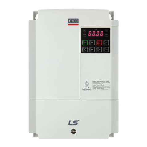
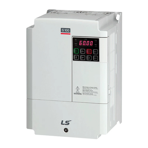
LSIS SV-iS7 series User manual

● Please read all safety precautions before
using this product.
● After reading this manual, please store it in
a location where it can be easily found.
Web Control Manual
SV - iS7
AC Variable Speed Drive
The best choice for your best interests!
LSIS works hard to ensure that all our clients receive the best possible
benefits.
www.lsis.com


About This Manual
iii
About This Manual
This manual discusses the specifications, features, installation, operation, and
maintenance of the iS7 Web Control. This manual is designed for users who
already have a basic understanding of inverters.
Please read this manual before using your inverter to fully understand the
performance, functionality, installation, and operation of this product. In addition
to this, please ensure that the end user and maintenance manager have read
this manual.

Safety Precautions
iv
Safety Precautions
Safety Precautions help you prevent accidents and use this product properly.
Make sure you adhere to all Safety Precautions outlined in this manual.
There are two types of symbols used in this manual: Warning symbols and
Caution symbols. These symbols indicate the following.
Precaution
Definition
Warning
This symbol indicates the possibility of electric shock.
Caution
This symbol indicates a protective conductor terminal.
The symbols displayed on the inverter and in the manual indicate the following.
Note
Failure to adhere to caution information may result in serious consequences,
depending on the situation.
The symbols displayed on the inverter and in the manual indicate the following.
Symbol
Definition
This symbol indicates a potential danger.
This symbol indicates the possibility of electric shock.
After reading this manual, please store it in a location where it can be easily
found.
Please read this manual carefully to ensure the safe and effective use of the iS7
Web Control.

Safety Precautions
v
Warning
Do not open the cover while the power is on or at any time during operation.
Doing so may result in an electric shock.
Do not operate the inverter while the cover is open.
Exposing the high voltage terminal or charging area to the external environment may
result in an electric shock.
Do not open the cover even when the power supply has been switched off. This
excludes necessary maintenance or regular inspection.
Opening the cover may result in an electric shock even if the power supply is off. The
inverter may hold a charge long after the power supply has been switched off.
Do not conduct maintenance or inspection without first ensuring that the DC
voltage of the inverter has been fully discharged. To ensure this, use a voltage
tester at least ten minutes after the power supply has been cut off.
Doing so may result in an electric shock. (DC 30 V or less)
Do not operate switches on the inverter with wet hands.
Doing so may result in an electric shock.
Do not use the inverter if the cable has been damaged.
Doing so may result in an electric shock.
Do not place heavy objects on the cable.
Placing heavy objects on the cable could damage its sheath and may result in an
electric shock.
Caution
Do not install the product near any flammable materials.
Mounting the inverter on or near flammable materials may start a fire.
Switch off the power supply to a faulty inverter.
Failure to switch off the power supply to a faulty inverter may start a fire.
Do not touch the inverter while the power supply is on or within ten minutes of
switching the power supply off.
Touching the inverter during this period may result in a burn due to the high operating
temperatures of this product.
Do not supply power to a faulty inverter even after it has been installed.
Doing so may result in an electric shock.
Make sure that foreign substances, such as screws, metal, water, and oil, do not
enter the inverter.
Introducing foreign substances to the inverter may start a fire.

Usage Precautions
vi
Usage Precautions
Transportation and Installation
Transport the product in a manner appropriate for its weight.
Install the product according to the procedures described in this manual.
Do not open the access panel during transport.
Do not place heavy objects on the product.
Install the product in the direction specified by this manual.
This inverter is a precision instrument. Do not drop it or expose it to hard
impact.
The inverter requires a special Class 3 grounding construction.
Immediately place any detached PCB on a protective conductor if you must
remove it for installation or repair. The inverter can be damaged by static
electricity.
Do not expose the inverter to snow, rain, mist or dust.
Do not obstruct the vents for the cooling fan. This could result in the inverter
overheating.
Make sure that power to the inverter is turned off before installation.
Ensure that all cables are in good condition. This will minimize the risk of fire
or electric shock. Do not use poor quality cables or extend the length of the
existing cable.
Only operate the inverter under the following conditions.
Item
Details
Environment
Temperature
-10℃ - 50℃ (Provided no ice or frost has formed.)
Humidity
90% RH or less (Provided no condensation has formed.)
Storage
temperature
-20 - 65℃
Environment
There should be no corrosive or flammable gas, oil residue,
dust, etc.
Altitude/Vibrations
Altitude of 1,000 m or lower/vibrations of 5.9 m/sec² (= 0.6 g)
or less
Ambient pressure
70 - 106 kPa

Usage Precautions
vii
Wiring
Do not install a phase advance capacitor, surge filter, or radio noise filter on
the output of the inverter.
Connect the output side terminals (R, S and T) in the correct order.
The inverter may be damaged if these terminals are incorrectly connected.
Be careful. Connecting the input side (terminals DCP, DCN) into the output
side (terminals R, S, T) incorrectly may damage the inverter.
Caution
Wiring or inspection must be performed by a qualified technician.
Fully install the inverter before wiring.
Starting the Inverter
Do not supply a voltage to any terminal if it exceeds the range outlined in the
manual. Excess voltage may damage the inverter.
Usage
Do not modify the interior workings of the inverter.
Disposal
Dispose of the inverter according to your local regulations regarding the
disposal of industrial waste.
Recycle all recyclable components contained in this inverter to preserve
energy and resources.
The packing materials and metal components of this product are recyclable
in most areas. Plastic parts are recyclable or may be burned in a controlled
environment, depending on local regulations.
Cleaning
Turn off the inverter prior to cleaning. Clean the inverter with a dry cloth.
Never use water or a wet cloth to clean the inverter.

Usage Precautions
viii
Long-term Storage
If you are not planning on using the inverter for a long period of time, store it
under the following conditions:
Store the inverter in an area which complies with the recommended storage
environment guidelines. (See page vi.)
If the storage period exceeds three months, store the inverter at a
temperature of between -10 and 30˚C to prevent thermal degradation of the
electrolytic capacitor.
Package the inverter to prevent moisture from accumulating inside it. Ensure
that the inverter is stored with a relative humidity of less than 70% by placing
a desiccant (silica gel) packet inside the packaging.
If the inverter is exposed to humidity or dust (e.g. if it is installed on
construction equipment), detach it from the equipment before storing it under
the conditions set forth on page vi.
Caution
If the inverter is not supplied with electricity for a long period of time, the electrolytic
condenser may suffer from thermal degradation. To prevent this from happening, connect
the power supply to the inverter for 30 - 60 minutes at least once a year. Do not perform
any wiring or other operation on the output (secondary) side of the inverter.

Table of Contents
ix
Table of Contents
ABOUT THIS MANUAL ...................................................................................................... III
SAFETY PRECAUTIONS ................................................................................................... IV
USAGE PRECAUTIONS ..................................................................................................... VI
TABLE OF CONTENTS ...................................................................................................... IX
1. PRECAUTIONS...................................................................................................... 1-1
1.1 Product Overview ................................................................................................... 1-1
1.2 Products with a Built-in Braking Resistor (capacity = less than 3.7 kW) .................. 1-1
2. WINDER/UNWINDER OPERATION ...................................................................... 2-1
2.1 Overview ................................................................................................................ 2-1
2.2 General Configuration ............................................................................................ 2-3
2.3 Main Speed Command Section .............................................................................. 2-8
2.4 Tension Command Section .................................................................................. 2-11
2.5 Web PID Controller Section .................................................................................. 2-16
2.6 Diameter Computation Section ............................................................................. 2-25
2.7 Final Speed Computation Section ........................................................................ 2-33
2.8 Analog Output Section ......................................................................................... 2-40
2.9 Final Tension Computation Section ...................................................................... 2-41
2.10 Web Break Detection Section ............................................................................... 2-42
2.11 Torque Limit Computation Section ........................................................................ 2-44
2.12 Web Function without Diameter Computation Section .......................................... 2-47
3. CAPSTAN OPERATION ......................................................................................... 3-1
3.1 Overview ................................................................................................................ 3-1
3.2 General Configuration ............................................................................................ 3-3
3.3 Main Speed Command Section .............................................................................. 3-4
3.4 Web PID Controller Section .................................................................................... 3-4
3.5 Analog Output Section ........................................................................................... 3-4
3.6 Web Break Detection Section ................................................................................. 3-4
3.7 Material Thickness Computation Section ................................................................ 3-5

Table of Contents
x
3.8 Final Speed Computation Section ........................................................................ 3-11
4. OTHER FUNCTIONS .............................................................................................. 4-1
5. APPLIED FUNCTIONS ........................................................................................... 5-1
5.1 Setting the Override Frequency Using the Aux Frequency Command .................... 5-1
5.2 Jog Operation (Jog-operating the Inverter) ............................................................. 5-5
5.3 Up – Down Operation ............................................................................................. 5-9
5.4 Wire Operation (Operating the Inverter with the Push Button or Equivalent) ........ 5-11
5.5 Safe Operation Mode (Using the Terminal Input to Limit Operation) ..................... 5-12
5.6 Dwell Operation (Operating the Inverter in Dwell Mode) ....................................... 5-14
5.7 Slip compensation operation ................................................................................ 5-16
5.8 PID Control .......................................................................................................... 5-18
5.9 Auto-tuning ........................................................................................................... 5-25
5.10 V/F Operation Using the Speed Sensor ................................................................ 5-31
5.11 Sensorless (I) Vector Control ................................................................................ 5-32
5.12 Sensorless (II) Vector Control ............................................................................... 5-34
5.13 Vector Control ...................................................................................................... 5-38
5.14 Torque Control (Controlling the Torque) ................................................................ 5-45
5.15 Droop Control ....................................................................................................... 5-47
5.16 Speed/Torque Switchover ..................................................................................... 5-47
5.17 Kinetic Energy Buffering ....................................................................................... 5-48
5.18 Energy Saving Operation ..................................................................................... 5-49
5.19 Speed Search Operation ...................................................................................... 5-50
5.20 Automatic Restart Operation ................................................................................ 5-54
5.21 Operation Sound Selection ................................................................................... 5-56
5.22 Second Motor Operation (with One Inverter) ........................................................ 5-58
5.23 Bypass Operation ................................................................................................. 5-60
5.24 Cooling Fan Control ............................................................................................. 5-61
5.25 Input Power Frequency Selection ......................................................................... 5-62
5.26 Inverter Input Voltage Selection ............................................................................ 5-62
5.27 Reading, Writing, and Saving Parameters ............................................................ 5-62
5.28 Parameter Initialization ......................................................................................... 5-63
Table of Contents
xi
5.29 Hide Parameter Mode and Prohibit Parameter Changes ...................................... 5-64
5.30 Add User Group (USR Grp) ................................................................................. 5-66
5.31 Add Macro Group ................................................................................................. 5-68
5.32 Easy Start ............................................................................................................. 5-69
5.33 Other Config (CNF) Mode Parameters ................................................................. 5-70
5.34 Timer Function ..................................................................................................... 5-71
5.35 Auto Sequence Operation .................................................................................... 5-72
5.36 Traverse Operation Function ................................................................................ 5-75
5.37 Brake Control ....................................................................................................... 5-76
5.38 Multi-Function Output On/Off Control Function ..................................................... 5-79
5.39 MMC Function ...................................................................................................... 5-80
5.40 Regeneration Evasion Function for Press ............................................................ 5-87
6. TABLE OF FUNCTIONS ........................................................................................ 6-1
6.1 Parameter Mode – Drive Group (DRV) ............................................................... 6-1
6.2 Parameter Mode – Basic Function Group (BAS) ................................................ 6-4
6.3 Parameter Mode – Expanded Function Group (PARADV) .................................. 6-8
6.4 Parameter Mode – Control Function Group (CON) ........................................... 6-13
6.5 Parameter Mode – Input Terminal Block Function Group (IN) ........................... 6-19
6.6 Parameter Mode – Output Terminal Block Function Group (OUT) .................... 6-24
6.7 Parameter Mode – Communication Function Group (COM) ............................. 6-30
6.8 Parameter Mode – Application Function Group (APP) ...................................... 6-35
6.9 Parameter Mode – Application Function Group 2 (AP2) ................................... 6-41
6.10 Parameter Mode – Option Card Function Group (APO) .................................... 6-42
6.11 Parameter Mode – Protection Function Group (PRT) ....................................... 6-44
6.12 Parameter Mode – 2nd Motor Function Group (M2) Note 50) ................................ 6-48
6.13 Trip mode (TRP Current (or Last-x)) ..................................................................... 6-49
6.14 Config Mode (CNF) .............................................................................................. 6-50
7. IS7 COMMUNICATION COMMON AREAS ........................................................... 7-1
7.1 iS7 Monitoring Common Areas ............................................................................... 7-1
7.2 Common Areas for iS7 Control ............................................................................... 7-8
7.3 Common Areas for iS7 Dedicated Product Monitoring .......................................... 7-10

Table of Contents
xii
7.4 Common Areas for iS7 Dedicated product control ................................................ 7-11
APPENDIX A SAMPLE WEB-ONLY PARAMETER SETTINGS ................................. A-1
A.1 Overview ................................................................................................................A-1
APPENDIX B SETTING THE PARAMETERS ............................................................. B-2
B.1 Setting Winder Parameters ....................................................................................B-2
B.2 Setting Unwinder Parameters .................................................................................B-3
B.3 Setting Capstan Parameters...................................................................................B-4
Warranty ............................................................................................................................B-5
Manual Revision History ....................................................................................................B-6

1. Precautions
1-1
1. Precautions
1.1 Product Overview
SV
0008
iS7
-
2
N
O
F
R
W
LS
Inverter
Applicable motor
capacity
Type
-
Input
voltage
Keypad
UL
EMC/
DCL
DBR
Control
0008
0.75 kW
Universal
inverter
2:
Three-
phase
200 - 230 V
4:
Three-
phase
380 - 480 V
N:
NON
S:
GLCD
(Graphic
loader)
O:
OPEN
E:
Enclosed
UL Type1
Note 1)
Blank:
Non-
EMC/
DCL
F:
EMC
D:
DCL
FD:
EMC,
DCL
Blank:
Non-
DB R
R:
DB R
(Braking
resistor,
built-in)
Note 2)
W:
Web
Control
0015
1.5 kW
0022
2.2 kW
0037
3.7 kW
0055
5.5 kW
0075
7.5 kW
0110
11 kW
0150
15 kW
0185
18.5 kW
0220
22 kW
0300
30 kW
0370
37 kW
0450
45 kW
0550
55 kW
0750
75 kW
0900
90 kW
1100
110 kW
1320
132 kW
1600
160 kW
Note 1) A Type 1 Enclosed product satisfies the requirements for adding a separate conduit option to an iS7 product. This applies to
all products with capacities ranging from 0.75 to 75 kW.
Note 2) Only products with capacities below 3.7 kW come equipped with a built-in braking resistor.

1. Precautions
1-2
1.2 Products with a Built-in Braking Resistor
(capacity = less than 3.7 kW)
If you want a high frequency braking resistor, please use a separate braking
resistor.
Voltage
Applicable inverter
capacity
(kW)
Usage
(%ED/Continuous
operation)
100% braking torque,
2%ED
Resistance
(Ω)
Watt
(W)
200 V
product
0.75
2% / 5 sec.
200
100
1.5
2% / 5 sec.
100
100
2.2
2% / 5 sec.
60
100
3.7
2% / 5 sec.
40
100
400 V
product
0.75
2% / 5 sec.
900
100
1.5
2% / 5 sec.
450
100
2.2
2% / 5 sec.
300
100
3.7
2% / 5 sec.
200
100
If you use a product with a built-in braking resistor (capacity = less than 3.7 kW),
make sure that PRT67 [DB RES SEL] is set to “Inside” and PRT66 [DB
Warn %ED] is set to 1 or 2 percent.
If [DB Warn %ED] is 0%, it means that there is no limit on the use of the braking
resistor. Continuously using the braking resistor in an environment that requires
frequent braking may burn out the braking resistor.
Moreover, for products with a built-in braking resistor, [DB Warn %ED] can be set
to 2% to limit capacity and protect the braking resistor. For environments that
require frequent braking, please select a product without a built-in braking
resistor and use a separate braking resistor.
2% usage means that, if the braking operation conditions are sustained for 100
seconds, braking is activated for 2 seconds only and is deactivated for the
remaining 98 seconds even under braking operation conditions.
Products with a built-in braking resistor can continuously operate the braking
resistor for 5 seconds. Thus, if the braking operation conditions are maintained,
braking is activated for 5 seconds but is deactivated for the next 245 seconds
even under braking operation conditions. Therefore, if the braking operation is
interrupted, the braking resistor is unavailable for at least 245 seconds (when set
at 2%).

2. Winder/Unwinder Operation
2-1
2. Winder/Unwinder Operation
2.1 Overview
Winders are also called “spoolers”. These components wind up web material
(iron wire, iron plate, steel wire, etc) as they maintain a constant tension in the
material. In contrast to this, unwinders unwind web material, as they maintain a
constant tension in the material.
Basically, the winder and unwinder in an iS7 inverter use analog feedback from
the tension control detectors, such as the dancer or load cell, to activate the PID
controller and maintain a constant tension. This way, the winder and unwinder
form a closed loop tension control system when winding and unwinding web
material. In addition, the characteristics of the PID controller in the closed loop
tension control system differ from existing PID controllers. That is why this
system is referred to as a “Web PID controller” in this manual.
However, even open loop tension control systems that do not use a Web PID or
tension control detectors like dancers and load cells can function using the
winder and unwinder from an iS7 inverter.
The tension control operation of an iS7 inverter can be broadly subdivided into
the winder/unwinder, closed loop/open loop, and speed/tension command
operations.
).1.11(.
][
][
][ Eq
mdiameter
mpmFlux
rpmSpeedMotor
The actual diameter (m) of the winder increases during operation. As shown in
Eq. 1.1.1, the motor speed (rpm) decreases as the diameter of the winder
increases to maintain a constant flux (mpm). The motor speed, i.e. output
frequency of the inverter, is reduced by activating the Web PID controller. In
addition to this, the Web PID controller computes and estimates the increases to
the diameter of the winder internally and uses the computed diameter ultimately
to decrease the output frequency of the inverter.
In contrast to the winder, the actual diameter (m) of the unwinder decreases
during operation. As shown in Eq. 1.1.1, the motor speed (rpm) increases as the
diameter of the winder decreases to maintain a constant flux (mpm). In a closed
loop tension control system, this motor speed, i.e. the output frequency of the
inverter, is increased by activating the Web PID controller. In addition to this, the
Web PID controller computes and estimates the decreases to the diameter of the
winder internally and uses the computed diameter ultimately to increase the
output frequency of the inverter.
This system offers more consistent control over the winder tension than
conventional PID controllers. Since the internally computed diameter
compensates for the inverter's output frequency once again, the Web PID
controller uses significantly less of the inverter's output frequency. Therefore, the

2. Winder/Unwinder Operation
2-2
Web PID controller does not risk saturating the output, which is effective in
significantly reducing the oscillation of the I controller output.
The Web PID controller also offers the following functions:
Eliminates the transient phenomenon that occurs with the dancer or load
cell at start up (related code: APP51).
Compensates for the inertia of the winder (related code: APP56-57).
Maintains the tension and, if necessary, performs an emergency stop
(related code: APP82).
Detects potential ruptures in the web material in advance (related code:
APP76-80).
You must comply with the following settings to ensure that the iS7 properly uses
the winder (spooler) or unwinder, or applies them to the closed or open loop
system.
Group
Code
number
Function
Name
Setting
APP
01
App Mode
Application selection
5: Tension Ctrl
APP
02
Tnsn Ctrl Mode
Tension control
operation mode
selection
0
W_Spd Close
1
UW_Spd Close
3
W_Tens Close
4
UW_Tens Close
5
W_Spd Open
6
UW_Spd Open
7
W_Tens Open
8
UW_Tens Open

2. Winder/Unwinder Operation
2-3
2.2 General Configuration
(1) Closed Loop Speed Control Mode
Main speed command section
Out1
Diameter computation section Out1
In1
In3
In2
Web break detection section
Out1In1
Web PID controller section
Out1
Out3
Out2
In2
Final speed computation
section
Out2
In1
In3
In2
In4 Out1
Analog output section
In1
In2
Tension command section
Out1
In1
Web function without diameter
computation section
In5
Out1
In1
In2
The following table outlines the inputs and outputs for each section.
Functional
section
Input
Output
Main speed
command
section
-
Out1
Main speed (%)
Tension
command
section
-
Out1
Tension command (%)
Web PID
controller
section
In1
Diameter (%)
Out1
Error change compensation
frequency (Hz)
Out2
PID Out (%)
In2
Tension command (%)
Out3
PID feedback (%)
Diameter
computation
section
In1
Current output frequency (Hz)
Out1
Diameter (%)
In2
Main speed (%)
In3
Web brake event (0/1)
Final speed
computation
In1
Error change compensation
frequency (Hz)
Out1
Final speed command (Hz)

2. Winder/Unwinder Operation
2-4
Functional
section
Input
Output
section
In2
Diameter (%)
In3
Main speed (%)
Out2
Main speed + PID (%)
In4
PID output (%)
In5
Compensation gain (%)
Analog output
section
In1
Main speed + PID (%)
-
In2
Main speed (%)
Open circuit
detection
section
In1
PID feedback (%)
Out1
Web brake event (0/1)
Web function
without
diameter
computation
section
In1
PID output (%)
Out1
Compensation gain (%)
In2
Current output frequency (Hz)

2. Winder/Unwinder Operation
2-5
(2) Closed Loop Tension Control Mode
Main speed command section
Out1
Diameter computation section Out1
In1
In3
In2
Web break detection section
Out1
In1
Web PID controller section
Out1
Out2
In2
Final tension computation
section
In1
In3
In2
Tension command section
Out1
In1
Speed
Feed-back
The following table outlines the inputs and outputs for each section.
Functional section
Input
Output
Main speed command
section
-
Out1
Main speed (%)
Tension command
section
-
Out1
Tension command (%)
Web PID controller
section
In1
Diameter (%)
Out1
PID Out (%)
In2
Tension command (%)
Out2
PID feedback (%)
Diameter computation
section
In1
Current frequency (Hz)
Out1
Diameter (%)
In2
Main speed (%)
In3
Web brake event (0/1)
Final tension
computation section
In1
Diameter (%)
-
In2
PID output (%)
In3
Tension command (%)
Open circuit detection
section
In1
PID feedback (%)
Out1
Web brake event (0/1)

2. Winder/Unwinder Operation
2-6
(3) Open Loop Speed Control Mode
Main speed command section
Out1
Diameter computation section Out1
In1
In3
In2
Web break detection section
Out1In1
Torque limit computation
section
Out1
In2
Final speed computation
section
In2
In1
Out1
Analog output section
In1
Tension command section
Out1
In1
In3
The following table outlines the inputs and outputs for each section.
Functional section
Input
Output
Main speed command
section
-
Out1
Main speed (%)
Tension command section
-
Out1
Tension command (%)
Torque limit computation
section
In1
Diameter (%)
Out1
Torque limit (%)
In2
Tension command (%)
In3
Current output frequency
(Hz)
Diameter computation
section
In1
Current output frequency
(Hz)
Out1
Diameter (%)
In2
Main speed (%)
In3
Web brake event (0/1)
Final speed computation
section
In1
Diameter (%)
Out1
Final speed command (Hz)
In2
Main speed (%)
Analog output section
In1
Main speed (%)
-
Open circuit detection
section
In1
Torque limit (%)
Out1
Web brake event (0/1)
Other manuals for SV-iS7 series
8
Table of contents
Other LSIS Controllers manuals

LSIS
LSIS XEC-DR32H User manual

LSIS
LSIS sv-ip5a User manual

LSIS
LSIS XGT Series User manual

LSIS
LSIS XBC-DN32U User manual

LSIS
LSIS XGL-CH2A User manual

LSIS
LSIS XGT Series User manual

LSIS
LSIS Master-K K200S User manual

LSIS
LSIS S100 Series Programming manual

LSIS
LSIS XGT Series User manual

LSIS
LSIS XBM-DN16S User manual

LSIS
LSIS XGT Series User manual

LSIS
LSIS XGT Series User manual

LSIS
LSIS XBC-DR20SU User manual

LSIS
LSIS XDL-L7NH Series User manual

LSIS
LSIS XDL-L7SA002X User manual

LSIS
LSIS XGT Series User manual

LSIS
LSIS XGT Series User manual

LSIS
LSIS MASTER-K200S Owner's manual

LSIS
LSIS XEC-DN32H/DC User manual

LSIS
LSIS XGT Series User manual