manuals.online logo
Brands
  1. Home
  2. •
  3. Brands
  4. •
  5. Honeywell
  6. •
  7. Security Sensor
  8. •
  9. Honeywell GENT S4-720 Instruction manual

Honeywell GENT S4-720 Instruction manual

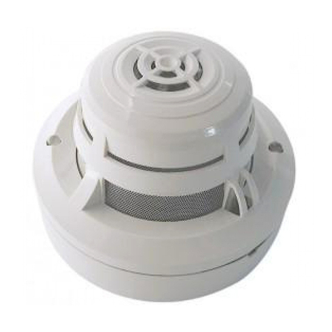
These instructions contain information on the S-Quad product
range. The S-Quad product integrates dual angle smoke, heat
and carbon monoxide gas detection with electronic sounder,
speech and LED flasher (Strobe) in one assembly.
Product range
All LPCB approved Sensor STATES are
listed in the S-Quad Description and
commissioning information .
Part number Description Symbol
S4-720 Heat Sensor H
S4-780 Heat Sensor &
Sounder
HS
S4-720-ST-VO Heat Sensor, Speech
& Strobe
HStSp
S4-715 # Optical Sensor # O #
S4-710 Optical & Heat Sensor OH
S4-770 Optical & Heat Sensor
plus Sounder
OHS
S4-770-ST Optical & Heat Sensor
plus Strobe
OHSt
S4-711 Dual Optical & Heat
Sensor
O2H
S4-771 Dual Optical & Heat
Sensor plus Sounder
O2HS
S4-711-ST Dual Optical & Heat
Sensor plus Strobe
O2HSt
S4-711-VO Dual Optical & Heat
Sensor plus Speech
O2HSp
S4-711-ST-VO Dual Optical & Heat
Sensor plus Speech &
Strobe
O2HSpSt
S4-911 Dual Optical, Heat &
CO Sensor
O2HCO
S4-911-ST-VO Dual Optical, Heat &
CO Sensor plus
Speech & Strobe
O2HCOSpSt
# This 'Optical' Sensor is for use in Vigilon Compact system.
Associated products
S4-700 S-Quad Base
S4-FLUSH Semi-Flush fixing kit
S4-COVER-DUST Sensor dust cover (50 pack)
S4-COVER-BASE Base dust cover (50 pack)
S4-EXTRACTOR Removal tool
S4-COVER-REMOVER Dust cover remover tool
(spare adaptor)
S4-BASE-LABEL Label plate (50 pack)
S4-BASE-GASKET Base IP Gasket (50 pack)
General specification
Operating voltage 35V - 41V
Weight 110g (with base - 170g)
S4-720 only:88g (with base -
148g)
Dimensions 117mm diameter by 49.6mm
height (With base the height
increases to 63.8mm)
IP rating IP30
IP20 when mounted on a metal
back box
Enclosure ABS
Colour RAL 9010
Approval LPCB approved
Storage Temperature -20°Cto70°C (for S-Quad
with CO -20°Cto50°C)
Ambient operating
temperature
-10°Cto50°C
Relative Humidity 95% non condensing
(5°C to 45°C)
Heat (H) Standard EN54 : Part 5 : 2002
Optical (O) Standard EN54 : Part 7 : 2000
Dual Optical (O2)
Standard
EN54 : Part 7 : 2000
Sounder (S) Standard EN54 : Part 3 :
Gas (CO) Standard * LPS 1274
Multi sensor standard CEA 4021
EN54-18 : 2005
EN54-17 : 2005
(section 4.8)
data:
Vmax 42V IC max 0.4A
Vnom 40V IS max 1A
Vmin 24V IL max 20mA
VSO max 16V ZC max 0.1W
VSO min 8V
* The 'Gas' sensing is designed to meet the requirements
of LPS 1274 : issue 1.0
Information on minimum sound output levels to include polar
dispersion is covered in a technical note TECH7018.033,
available on request from manufacturer.
4188-779 issue 8-7_08/10_S-Quad _Part 1 1
Data and Installation
S-Quad
Sensor, Sounder, Speech & Strobe
by Honeywell
www.acornfiresecurity.com
Siting
A S-Quad device plugs into a dedicated Base that is installed in
the protected premises. The Bases should be sited in locations
as defined by the project plans and by BS5839 : Part 1 : 2002.
Do's and Don't
&
DO NOT locate smoke detectors where products of
combustion may be present such as kitchens,
garages, furnace rooms, welding shops etc.
DO NOT locate heat detectors above boilers or
heaters or where the temperature is normally very
high or liable to sudden fluctuations.
DO NOT locate smoke or heat detectors: -
• In dusty or dirty environment.
• Near heating or air-conditioning grilles.
• Outdoors in stables, sheds etc.
• In excessively damp areas.
• In dead air spaces at the junctions of
ceilings and walls.
• At ceiling locations where a ‘thermal
barrier' may exist.
DO NOT locate a CO detector: -
• In buildings where farm animals are kept.
• In excessive damp areas.
• In battery room where non sealed battery
are kept.
• In a Car park where exhaust fumes will
be present.
Follow recommendations detailed in section 22 of
BS5839 : Part 1 : 2002
Metal back box
A metal back box must be used for base or semi-flush mounting.
The earth continuity must be maintained throughout the whole
loop. The earth must be securely connected to the back box.
In - Out wiring to S-Quad bases
Programmable input/output
&The 34703 Slave Relay unit and 34703
Slave LED indicator unit are NOT supported for use
with S-Quad fire sensors. The Slave units are only
compatible with 34xxx range of fire sensors.
All S-Quad devices can be configured as either monitored input
or unmonitored output. The factory setting of the programmable
input / output is unmonitored output, to drive an external repeat
LED without a series resistor.
There is a maximum cable length limit of 15 metres from the
S-Quad base to the external I/O Unit.
The input can accept signals such as fire, non fire or fault, these
are configured during commissioning. As a fire input it is possible
to connect a conventional Manual Call Point (non UK application
only) with a series resistor of value 470 Ohms coupled with an
end-of-line 10Kohms resistor. In this case the fire input is fully
monitored for open or short circuit faults.
The input can be setup as a non-fire or fault input using a similar
arrangement with series and parallel resistors as shown. It is
possible for such an input to trigger a command that is
configured to action an output elsewhere in the system to control
plant equipment such as the ventilation system.
Data and Installation S-Quad
2 4188-779 issue 8-7_08/10_S-Quad _Part 1
LOOP CABLE
STANDARD 60mm METAL BACK BOX
CABLE GLAND
LOOP CABLE
S-QUAD BASE
CEILING TILE
2 SCREWS TO SECURE
BASE TO METAL BACK BO
X
CROSS SECTION
OF CEILING TILE
EM2
OUT5
IN4 C3
EM2
OUT5
IN4 C3
L1 0V
L2
L1
0V
L2
EM2
OUT5
IN4 C3
L1 0V
L2
+
-
+-
Unmonitored LED output
+-
Remote LED unit
1344
9
-01
+-+-
+-+-
EM2
OUT5
IN4 C3
L1 0V
L2
470 W
10 KW
I
nput
www.acornfiresecurity.com
Tools
An extractor tool allows removal and fitting of the S-Quad device
head into the base. By fitting a screw-on adaptor, the tool can be
used to remove the sensor dust cover.
To remove the S-Quad
Fit the tool onto the S-Quad. Turn S-Quad anticlockwise until it
stops and then remove the S-Quad from the base.
To fit an S-Quad
Fit the S-Quad on to the tool. Offer S-Quad to base and rotate
clockwise until it moves upwards on to the base and rotate it
again until it clicks and goes no further, the lines on the base and
S-Quad will align.
To fit the dust cover using tool
Place the dust cover onto the tool inside the cradle. Offer the
cover to the S-Quad, locate and push to fit it onto the assembly.
Withdraw the tool when the dust cover is in place.
To remove the dust cover using tool
A dust cover remover tool must be fitted to the main tool to
extract the dust cover. Press the pad of the dust cover remover
tool onto the dust cover, this creates an air tight grip, to allow the
cover to be pulled off from the S-Quad.
4188-779 issue 8-7_08/10_S-Quad _Part 1 3
S-Quad Data and Installation
B
ase
S-Quad
Tool
Tool
Dust cover
S-Quad
Tool
Tool
Dust cover
remover tool
D
ust cover
www.acornfiresecurity.com
S-Quad Semi-flush
fixing kit (S4-FLUSH)
An S-Quad device can be semi-flush mounted to a ceiling tile to a
depth of the approximate 20mm, which is slightly deeper than the
base assembly. To semi-flush mount a special housing must be
used, which consists of a main assembly and a trim ring.
"There is an enhanced volume output of sound
and speech from a flush mounted S-Quad.
Technical data
Weight 164g with trim ring
Dimensions 174mm diameter by 50mm depth
Enclosure ABS
Colour RAL 9010
Storage Temperature -20°C to 70°C
Ambient temperature -10°C to 50°C
Relative Humidity 95% non condensing
(5 to 45°C)
Further information about
these products can be found
in Part 2 of this document
available on Gent Expert
website.
Data and Installation S-Quad
Gent by Honeywell reserves the right to revise this publication from time to time and make changes to the content hereof without
obligation to notify any person of such revisions of changes.
Hamilton Industrial Park, Waterside Road, Leicester LE5 1TN, UK Website: www.gent.co.uk
Telephone +44 (0) 116 246 2000 Fax (UK): +44 (0)116 246 2300
4 4188-779 issue 8-7_08/10_S-Quad _Part 1
Do not dispose of with your normal household waste.
Do not burn.
WEEE Directive:
At the end of their useful life, the packaging,
product and batteries should be
disposed of via a suitable recycling centre.
At the end of their useful life, the packaging,
product and batteries should be disposed of
via a suitable recycling centre and in
accordance with national or local legislation.
0832
Gent by Honeywell
Hamilton Industrial Park,
140 Waterside Road,
Leicester LE5 1TN, UK
Product EC Certification
No. of Conformity No.
S4-710 0832-CPD-0706
S4-711-VO 0832-CPD-0608
S4-715 0832-CPD-0707
S4-720 0832-CPD-0516
S4-720-ST-VO 0832-CPD-0609
S4-771 0832-CPD-0511
S4-770 0832-CPD-0708
S4-780 0832-CPD-0517
S4-911 0832-CPD-0515
S4-911-ST-VO 0832-CPD-0512
S4-711 0832-CPD-0513
S4-711-ST 0832-CPD-0514
S4-711-ST-VO 0832-CPD-0510
S-Quad
Trim ring
Cross section
of Ceiling Tile
Flush shroud
S-Quad Base
Do not over tighten the clamping
screws as this will cause the
clamps to cut into the ceiling tile.
Metal back box
Cut a 140mm
diameter hole in the
ceiling tile.
(
)
If required use a Bi-Metal Holesaw
140mm or 146mm, from
www.shop4tools.co.uk
Insert the flush shroud
assembly into the hole
in the ceiling tile.
Hold the flush shroud
to the ceiling tile and tighten
the three screws to splay the
clamps to secure the shroud to the tile.
Locate the S-Quad Base into
the flush shroud, such that the
two locating pillars on the
shroud feeds through the two
elongated holes on the Base.
Push the Base into the shroud
until the Base click locks into
the shroud.
Offer the trim ring to the shroud
and slowly rotate ring clockwise until it
clicks and goes no further. This will
lock the ring in position.
Fit the metal box onto the back
of the flush shroud using the
appropriate fixing screws to secure
the box to the flush shroud.
Offer the S-Quad to the Base
and rotate the S-Quad clockwise
until it moves upwards into Base,
and then rotate the S-Quad again
until it clicks and
g
oes no further.
Make the cable connections.
Clamp
www.acornfiresecurity.com

This manual suits for next models

13

Other Honeywell Security Sensor manuals

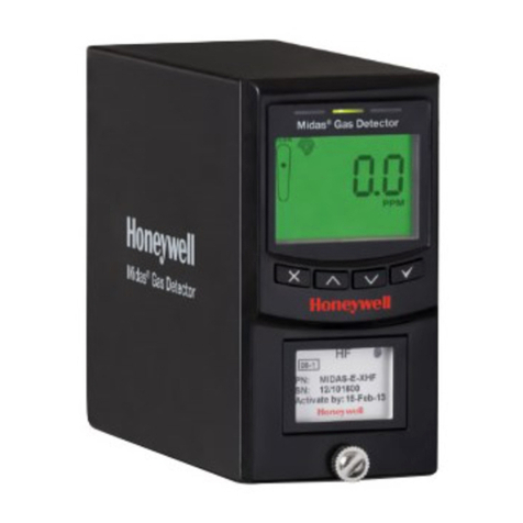
Honeywell Midas User manual

Honeywell

Honeywell Midas User manual

Honeywell XT Series User manual

Honeywell

Honeywell XT Series User manual

Honeywell Sensepoint XCD RFD User manual

Honeywell

Honeywell Sensepoint XCD RFD User manual

Honeywell HS3PIR1X User manual

Honeywell

Honeywell HS3PIR1X User manual

Honeywell DT7235T User manual

Honeywell

Honeywell DT7235T User manual

Honeywell SiX Series User manual

Honeywell

Honeywell SiX Series User manual

Honeywell FlexGuard 5853AP User manual

Honeywell

Honeywell FlexGuard 5853AP User manual

Honeywell FG-730 User manual

Honeywell

Honeywell FG-730 User manual

Honeywell Miller TurboLite Series Operator's manual

Honeywell

Honeywell Miller TurboLite Series Operator's manual

Honeywell BW Ultra User manual

Honeywell

Honeywell BW Ultra User manual

Honeywell 5800CO Assembly instructions

Honeywell

Honeywell 5800CO Assembly instructions

Honeywell NFPA 1971 Owner's manual

Honeywell

Honeywell NFPA 1971 Owner's manual

Honeywell Farenhyt Series User manual

Honeywell

Honeywell Farenhyt Series User manual

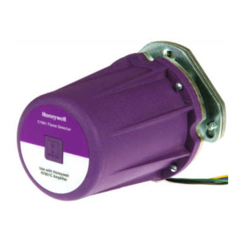
Honeywell C7061A1020 User manual

Honeywell

Honeywell C7061A1020 User manual

Honeywell SiX Series User manual

Honeywell

Honeywell SiX Series User manual

Honeywell AreaRAE Plus User manual

Honeywell

Honeywell AreaRAE Plus User manual

Honeywell ADEMCO 5808EU User manual

Honeywell

Honeywell ADEMCO 5808EU User manual

Honeywell Sensepoint User manual

Honeywell

Honeywell Sensepoint User manual

Honeywell HAQSPA User manual

Honeywell

Honeywell HAQSPA User manual

Honeywell DUAL TEC DT8050A User manual

Honeywell

Honeywell DUAL TEC DT8050A User manual

Honeywell Ex-Or MLS2500D Installation and operation manual

Honeywell

Honeywell Ex-Or MLS2500D Installation and operation manual

Honeywell Eclipse Instruction Manual

Honeywell

Honeywell Eclipse Instruction Manual

Honeywell RAELink3 2.4GHz User manual

Honeywell

Honeywell RAELink3 2.4GHz User manual

Honeywell MILLER 1032363 User manual

Honeywell

Honeywell MILLER 1032363 User manual

Popular Security Sensor manuals by other brands

CPS Leak-Seeker I Operation manual

CPS

CPS Leak-Seeker I Operation manual

Argus Security L-OP-SG Installation guides

Argus Security

Argus Security L-OP-SG Installation guides

RKI Instruments 35-3001A-02 Operator's manual

RKI Instruments

RKI Instruments 35-3001A-02 Operator's manual

Hubbell Compass CCE manual

Hubbell

Hubbell Compass CCE manual

CAME PXWIRCE manual

CAME

CAME PXWIRCE manual

SPX Radiodetection RD7000+ Operation manual

SPX

SPX Radiodetection RD7000+ Operation manual

STEINEL DALI-2 IR 180 manual

STEINEL

STEINEL DALI-2 IR 180 manual

DSC MAXSYS RF4164-433 instruction manual

DSC

DSC MAXSYS RF4164-433 instruction manual

Carrier BN Series specification

Carrier

Carrier BN Series specification

Argus Security Taurus TW-DT-01/916 manual

Argus Security

Argus Security Taurus TW-DT-01/916 manual

iRay Technology Mars1717X user manual

iRay Technology

iRay Technology Mars1717X user manual

LEGRAND CP Electronics EBDHS-KNX installation guide

LEGRAND

LEGRAND CP Electronics EBDHS-KNX installation guide

Powerfix Profi 271367 Operation and safety notes

Powerfix Profi

Powerfix Profi 271367 Operation and safety notes

Glasdon GLENWOOD 170 POST Installation and maintenance instructions

Glasdon

Glasdon GLENWOOD 170 POST Installation and maintenance instructions

THEIS TE 90 instruction manual

THEIS

THEIS TE 90 instruction manual

Mustang Survival MSD901 user manual

Mustang Survival

Mustang Survival MSD901 user manual

systemax Poolnanny installation guide

systemax

systemax Poolnanny installation guide

iBeam TE-BPCIR product manual

iBeam

iBeam TE-BPCIR product manual

manuals.online logo
manuals.online logoBrands
  • About & Mission
  • Contact us
  • Privacy Policy
  • Terms and Conditions

Copyright 2025 Manuals.Online. All Rights Reserved.