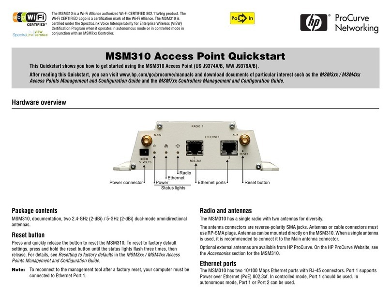
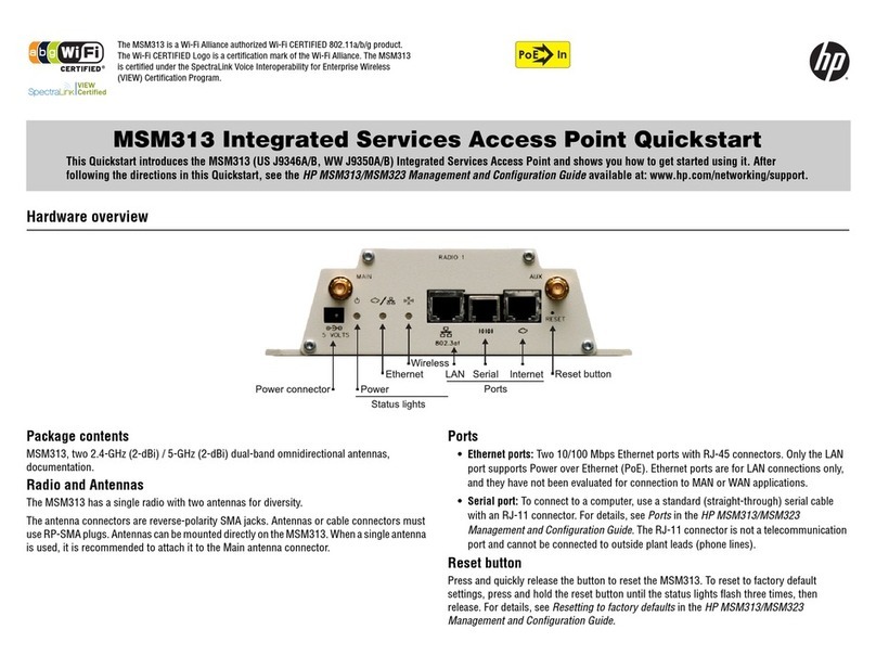
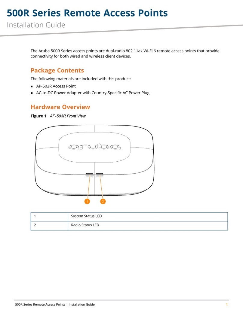
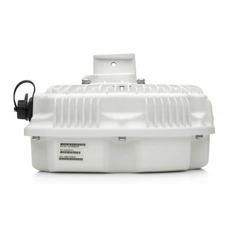
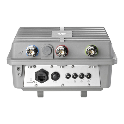
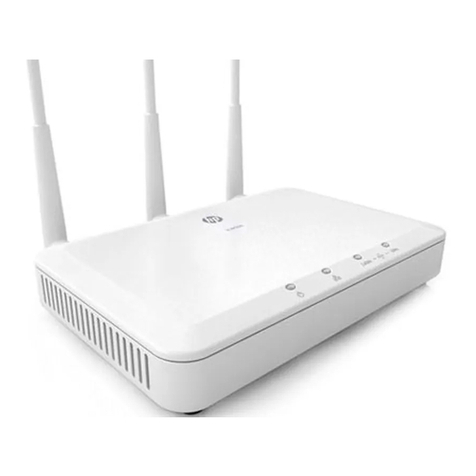
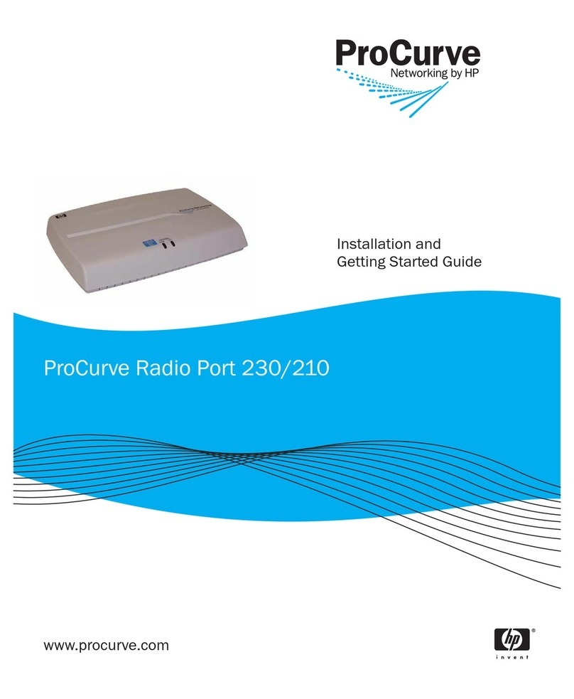
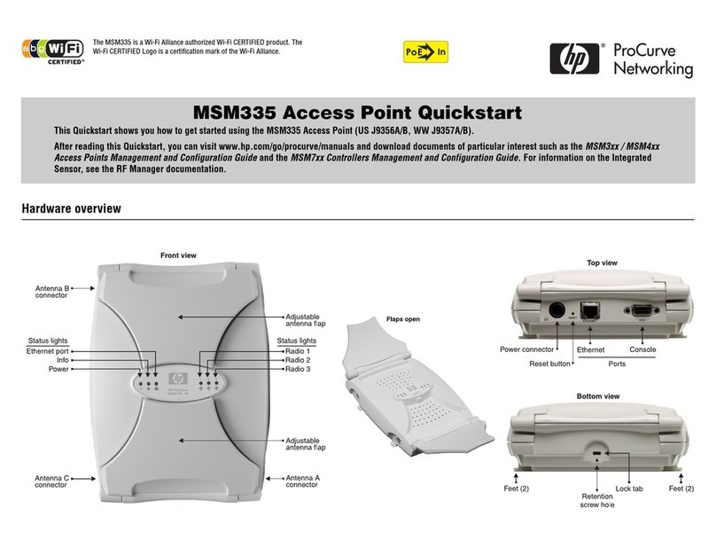
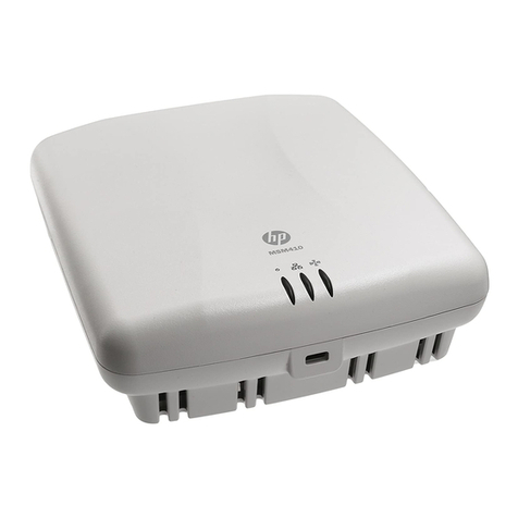
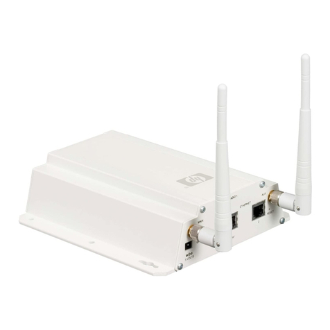
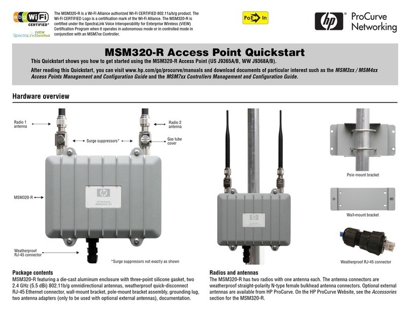
HP MSM310-R User manual

HP MSM310-R/320-R Outdoor AP
Installation Guide
Abstract
This document describes how to install and initially configure the HP MSM310-R/320-R Outdoor Access Points (hereafter
referred to as the AP). Professional wireless and electrical equipment experience is required. The main configuration information
for autonomous mode is found in the MSM3xx / MSM4xx APs Configuration Guide. The main configuration information for
controlled mode is found in the MSM7xx Controllers Configuration Guide.
HP Part Number: 5998-3771
Published: March 2013
Edition: 1

© Copyright 2013 Hewlett-Packard Development Company, L.P.
The information contained herein is subject to change without notice. The only warranties for HP products and services are set forth in the express
warranty statements accompanying such products and services. Nothing herein should be construed as constituting an additional warranty. HP shall
not be liable for technical or editorial errors or omissions contained herein.
Acknowledgments
Microsoft®, and Windows® are U.S. registered trademarks of Microsoft Corporation.
Warranty
WARRANTY STATEMENT: See the warranty information sheet provided in the product box and available online.

Contents
1 Preparing for installation.............................................................................5
Product models.........................................................................................................................5
Package contents......................................................................................................................5
Additional equipment needed....................................................................................................5
Identifying AP components.........................................................................................................6
Ports...................................................................................................................................6
Radio and antenna..............................................................................................................7
Important information to read before installing..............................................................................7
Professional installation required............................................................................................7
Surge protection and grounding............................................................................................7
Cabling..............................................................................................................................7
Country of use.....................................................................................................................7
External antennas................................................................................................................7
Safety................................................................................................................................8
Resetting to factory defaults........................................................................................................8
2 Installation.................................................................................................9
Antenna position......................................................................................................................9
Step 1: Plan the installation........................................................................................................9
Step 2: Install cabling.............................................................................................................10
Step 3: Prepare the weatherproof Ethernet cable........................................................................10
Step 4: Install the AP...............................................................................................................11
Powering the AP.....................................................................................................................12
3 Initially Configuring (Autonomous mode).....................................................13
About controlled mode and autonomous mode...........................................................................13
Initial configuration (autonomous mode)....................................................................................13
Step 1: Configure your computer..........................................................................................13
Step 2: Connect the cables and power on the AP...................................................................13
Step 3: Switch the AP to autonomous mode...........................................................................13
Step 4: Log in....................................................................................................................14
Step 5: Configure basic wireless protection...........................................................................14
Step 6: Assign an IP address to the AP.................................................................................14
Step 7: Test the wireless network..........................................................................................15
Step 8: Perform additional configuration...............................................................................15
4 Support and other resources......................................................................16
Online Documentation.............................................................................................................16
Contacting HP........................................................................................................................16
HP Websites..........................................................................................................................16
Typographic conventions.........................................................................................................16
A Regulatory information..............................................................................17
Notice for U.S.A.....................................................................................................................17
Manufacturer's FCC Declaration of Conformity statement........................................................17
FCC Class B statement........................................................................................................17
Notice to professional installers............................................................................................17
Exposure to radio frequency energy.....................................................................................18
Notice for Canada.................................................................................................................18
Notice for the European Community..........................................................................................18
Countries of operation & conditions of use............................................................................18
Notice for Brazil, Aviso aos usuários no Brasil............................................................................19
Notice for Taiwan...................................................................................................................20
Contents 3
DGT LPD (Low Power Device) statement.................................................................................20
Korean notices.......................................................................................................................20
Class B equipment.............................................................................................................20
Turkish recycling notice............................................................................................................20
Vietnamese Information Technology and Communications compliance marking...............................20
B Recycle statements....................................................................................21
Waste Electrical and Electronic Equipment (WEEE) statements......................................................21
English recycling notice......................................................................................................21
Bulgarian recycling notice...................................................................................................21
Czech recycling notice........................................................................................................21
Danish recycling notice.......................................................................................................21
Dutch recycling notice.........................................................................................................21
Estonian recycling notice.....................................................................................................22
Finnish recycling notice.......................................................................................................22
French recycling notice.......................................................................................................22
German recycling notice.....................................................................................................22
Greek recycling notice........................................................................................................22
Hungarian recycling notice.................................................................................................22
Italian recycling notice........................................................................................................23
Latvian recycling notice.......................................................................................................23
Lithuanian recycling notice..................................................................................................23
Polish recycling notice.........................................................................................................23
Portuguese recycling notice.................................................................................................23
Romanian recycling notice..................................................................................................24
Slovak recycling notice.......................................................................................................24
Spanish recycling notice.....................................................................................................24
Swedish recycling notice.....................................................................................................24
4 Contents

1 Preparing for installation
Product models
This document applies to these HP APs:
JapanUSAWWModel
J9380A/BJ9383A/BMSM310-R
J9528A/BJ9365A/BJ9368A/BMSM320-R
”WW” identifies worldwide regions not otherwise explicitly named.
Package contents
•The AP
•Two 2.4 GHz (5.5 dBi) 802.11b/g omnidirectional antennas
•One weatherproof quick-disconnect RJ-45 Ethernet connector
•One wall-mount bracket
•One pole-mount bracket assembly
•One grounding lug
•Two antenna adapters (only to be used with optional external antennas)
•Documentation
Additional equipment needed
In addition to the items supplied with the AP, protection equipment will be required according to
your electrical code. For example:
•Antenna surge suppressor: HP Antenna Lightning Arrester, J8996A.
•Ethernet surge suppressor: Weatherproof PoE compatible 10/100 base-T CAT5 Lightning
Protector.
Product models 5

Identifying AP components
1
4
5
2
3
6
MSM310-R / MSM320-R
1: Main antenna (MSM310-R) / Radio 1 antenna
(MSM320-R)
2: Auxiliary antenna (MSM310-R) / Radio 2 antenna
(MSM320-R)
3: Gas tube cover
4: Surge suppressors (not exactly as shown)
5: Weatherproof RJ-45 connector
6: Pole-mount bracket
7: Wall-mount bracket
7
5
Ports
The AP has a single 10/100 Mbps Ethernet port with weatherproof RJ-45 connector. Power over
Ethernet (PoE) 802.3af is used to power the AP.
The MSM310-R/MSM320-R is a ruggedized version of the MSM310/MSM320 and shares the
same feature set. However, due to its weatherproof enclosure, Ethernet Port 2, the status lights,
and the reset button are not available.
6 Preparing for installation

Radio and antenna
The MSM310-R has a single radio, with two antennas for diversity.
The MSM320-R has two radios, each with two antennas for diversity.
Important information to read before installing
It is strongly recommended that you work with the AP and confirm its operation before installing
it outdoors.
Professional installation required
WARNING! Prior to installing or using the AP, consult with a professional installer trained in RF
installation and knowledgeable in local regulations including building and wiring codes, safety,
channel, power, indoor/outdoor restrictions, and license requirements for the intended country. It
is the responsibility of the end user to ensure that installation and use comply with local safety and
radio regulations.
Surge protection and grounding
WARNING! Make sure that proper lightning surge protection and grounding precautions are
taken according to local electrical code. Failure to do so may result in personal injury, fire,
equipment damage, or a voided warranty. The HP hardware warranty provides no protection
against damage caused by static discharge or a lightning strike.
Cabling
You must use the appropriate cables, and where applicable, surge protection, for your given
region. For compliance with EN55022 Class-B emissions requirements, use shielded Ethernet
cables. Cat 5e (or better) cabling is required.
Country of use
CAUTION: In some regions, you are prompted to select the country of use during setup. Once
the country has been set, the AP will automatically limit the available wireless channels, ensuring
compliant operation in the selected country. Entering the incorrect country may result in illegal
operation and may cause harmful interference to other systems.
External antennas
CAUTION: When using an external antenna, depending on the country of use, the antenna
selected, and your radio settings, it may be mandatory to reduce the radio transmission power
level to maintain regulatory compliance. For specific power limits for your country, consult the
Antenna Power-Level Setting Guide (for MSM Products) available from www.hp.com/support/
manuals. Search by antenna product name or number.
To set the radio power transmission level for controlled access points see Transmit power control
in the MSM7xx Controllers Configuration Guide. For autonomous access points, see Transmit
power control in the MSM3xx / MSM4xx APs Configuration Guide.
Important information to read before installing 7

Safety
Take note of the following safety information during installation.
•If your network covers an area served by more than one power distribution system, be sure
all safety grounds are securely interconnected.
•Network cables may occasionally be subject to hazardous transient voltages (caused by
lightning or disturbances in the electrical power grid).
•Handle exposed metal components of the network with caution.
•The AP is powered-on when the Ethernet port is plugged into a PoE power source.
Resetting to factory defaults
The easiest way to reset the AP to factory defaults is with its management tool. When management
tool access is unavailable (forgotten password or IP address, for example), follow the procedure
Resetting to factory defaults in the MSM3xx / MSM4xx APs Configuration Guide.
8 Preparing for installation

2 Installation
Antenna position
The antenna flaps can be adjusted to optimize radio performance. Start with the following positions,
then adjust as needed. (See also the MSM310-R/MSM320-R Antenna Technical Note available
with the other online documentation.)
WARNING! The AP must be installed with the antennas pointing straight up. Damage caused
by water ingress through the RJ-45 connector as a result of the AP; being improperly installed or
the improper assembly or attachment of the weatherproof RJ-45 connector, is not covered by the
warranty.
WARNING! Corrosive damage caused by salt fog is not covered by the warranty.
The AP is typically interconnected with other equipment as follows (only the antennas and
weatherproof RJ-45 connector are supplied with the AP):
1
3
2
4 5
6
AP topology
4: Broadband router1: Internet
5: Broadband modem2: Ethernet surge suppressor
6: Indoors3: PoE Injector
WARNING! This is a general procedure. It is the installer's responsibility to perform the installation
according to local electrical code and regulations.
Step 1: Plan the installation
Identify a suitable install location. The AP has a NEMA 4 rating and is unsuitable for installation
in a salt fog environment. Local electrical and building codes and regional regulations will dictate
many aspects of your installation. It is recommended that you perform transmission and reception
tests at a proposed location before installing. In some cases it may be desirable to install remote
antennas, off the body of the AP.
You will have to provide an effective earth ground for the AP, at least one of its antenna surge
suppressors, and the Ethernet surge suppressor. It is rarely sufficient to use a metal pole for any
equipment grounding. You will also need to decide how to route the Ethernet cable from the building
to the AP.
Antenna position 9

Step 2: Install cabling
According to your needs and local electrical codes and regulations, run grounding wires and
Ethernet cable to where the AP will be installed. For the Ethernet cable, allow for an extra 0.6
meters (two feet) for connector attachment and drip loops. In addition, allow for an extra 1.2
meters (four feet) of cable for the Ethernet surge suppressor.
Step 3: Prepare the weatherproof Ethernet cable
To provide a weatherproof seal, the Ethernet port on the AP uses a custom weatherproof cable
connector (supplied). You must terminate your Ethernet cable with this connector as described in
the following procedure. Cable length should not exceed 91 meters (300 feet).
CAUTION: Ruggedized Ethernet cables must be used for outdoor cable runs.
1. Carefully unpack the nine quick-disconnect items from the plastic bag, identifying all parts as
illustrated. If any parts are missing, DO NOT proceed until you get a replacement parts kit.
Weatherproof connector parts
7: RJ-45 plug4: Gasket1: Sealing nut
8: RJ-45 Gaskets5: Screw nut2: Seal
6: Body3: Clamp ring
5 6 7 84321
2. If your Ethernet cable already has an RJ-45 connector on the end that will connect to the HP
equipment, remove the RJ-45 connector by cutting the cable at least 1.2 cm (.5 inch) before
the RJ-45 connector. Be sure to make a clean cut with a pair of sharp angle cutters. The
complete cut (through both the cable sheath and all wires) must occur in a single cutting motion.
3. Hold Clamp Ring (3) horizontally, with its fingers to the left. Insert the Seal (2) into the fingers
on the left end so that it is flush with the end of the fingers. Insert the Gasket (4) into the right
end, pushing it against the ridge at the end of the threads. The Gasket is beveled on one side.
The beveled side should face inwards away from the Screw Nut.
4. Thread the Sealing Nut (1) onto the left end of the Clamp Ring (3). Tighten it only enough for
it to stay attached.
5. Hold the Screw Nut (5) vertically, with the open threads facing up, and drop the Body (6) into
it, with the RJ-45 connector opening facing up.
6. Hold the Clamp Ring (3) vertically below the Screw Nut/Body items and screw the Body into
the threads on the Clamp Ring (3). Tighten it only enough to stay attached. Note that the
Screw Nut (5) remains loose on the Body (6).
7. Remove the white backing paper from one of the RJ-45 Gaskets (8) and press the glued side
onto the Body (6) being very careful to align the gasket with the RJ-45 connector shape on
the Body (6).
8. Remove the backing paper from the second RJ-45 Gasket (8) and press it over the first one,
being sure to maintain alignment.
9. Tighten the threads between Body (6) and Clamp Ring (3) by hand. DO NOT tighten between
Clamp Ring (3) and Sealing Nut (1). Do not over tighten. Do not tighten with tools.
The quick-disconnect assembly should now look like this when held horizontally, with the
Sealing Nut (1) at the left end, and the Screw Nut (5) over the Body (6) on the right.
10 Installation

10. Carefully thread the cleanly-cut end of the Ethernet cable through the Sealing Nut (1) end of
the quick-disconnect assembly, and push through approximately 30 cm (1 foot) of cable.
NOTE: The next two steps should be performed by someone with experience building Ethernet
cables.
11. Prepare the cable and attach it to the RJ-45 Plug (7) according to the directions included with
your crimping tool.
12. Before continuing, test the cable with a portable Ethernet cable tester to ensure that the RJ-45
plug (7) is correctly connected.
13. Carefully pull the cable slack back through the quick-disconnect assembly until the RJ-45 Plug
(7) is almost touching the Body (6). Adjust the cable position so that the RJ-45 Plug (7) fits
precisely into the RJ-45 cutout in the Body (6), and press down the plastic tab so the plug fits
correctly.
14. Tighten the threads between Sealing Nut (1) and Clamp Ring (3) by hand, until the cable is
firmly anchored. Do not over tighten. Do not tighten with tools.
Step 4: Install the AP
1. Mount the AP on a wall or pole using the supplied brackets so that the antennas are pointing
up. Local electrical and building codes will dictate many installation aspects.
2. Attach the supplied grounding lug (through the bracket) to one of the lower screw holes on
the AP body, and attach a grounding wire with the set screw.
(See figure in sub-step 4 below: "Grounded body (via grounding lug).")
3. Manually screw on antenna surge suppressors to the antenna connectors on top of the AP.
Position the gas tube covers so that they can be removed for future tube replacement. Attach
the two supplied antennas.
NOTE: If installing an optional HP antenna, first attach the lightning arrester to the AP, attach
the antenna adapter to the arrester, then attach the antenna connector to the adapter. See
also the antenna documentation.
4. Attach a grounding wire to at least one of the antenna surge suppressors. For the model
shown, remove the crimp connector, crimp it to the wire, and then screw the crimp connector
back onto the surge suppressor.
Grounded body (via grounding lug)Grounded surge suppressor
5. Create a drip loop in the Ethernet cable below the AP. A drip loop provides additional
protection against water running down the Ethernet cable and into the connector. Form the
Step 4: Install the AP 11

loop as shown here. Make sure that the distance between the loop start and end points is at
least 15 cm (6 inches), and that the cable hangs down at least 25 cm (10 inches).
10 inches
(25 cm)
6 inches
(15 cm)
Drip loop
6. (See illustration Weatherproof connector parts (page 10).) Mate the RJ-45 Plug (G) with the
socket on the AP, hold it firmly in place, and tighten the Screw Nut (E) by hand. Do not over
tighten. Do not tighten with tools.
7. Install an Ethernet surge suppressor as close as possible to the AP, ideally within .6 meters
(two feet). This helps reduce the effects of any charge carried by the cable to the AP. Install
this Ethernet surge suppressor between the AP and the PoE power source.
The Ethernet cable will typically need to be cut and have the cable end coming from the PoE
injector connected to the Ethernet surge suppressor input (Line) and have the cable end coming
from the AP connected to the Ethernet surge suppressor output (Equipment). Follow the
instructions included with the Ethernet surge suppressor. Include a drip loop for both the input
and output cables. Connect a grounding wire to the Ethernet surge suppressor.
Powering the AP
The AP can be powered by:
•A 10/100 or 10/100/1000 PoE-enabled switch. PoE-enabled switches are available from
HP.
•An HP 1-Port Power Injector (J9407A).
12 Installation

3 Initially Configuring (Autonomous mode)
About controlled mode and autonomous mode
The AP can operate in one of two modes: controlled (the default) or autonomous. Switching modes
resets all configuration settings to factory defaults.
•Controlled mode: To become operational, the AP must establish a management tunnel with
an MSM7xx Controller. The controller manages the AP and provides all configuration settings.
Discovery of the controller is automatic if default settings are used on the AP and the controller,
and both devices are on the same subnet. See Working with controlled APs in the MSM7xx
Controllers Configuration Guide.
•Autonomous mode: After being switched to autonomous mode, the AP operates as a stand-alone
AP. You configure and manage an autonomous AP by using its Web-based management tool
as described in “Initial configuration (autonomous mode)” (page 13).
Initial configuration (autonomous mode)
This procedure describes how to switch a factory-default AP to autonomous mode and then perform
its initial configuration that enables you to establish a wireless connection through the AP to the
Internet.
In autonomous mode, the AP is managed via its Web-based management tool as described in this
section. This requires at least Microsoft Internet Explorer 8+ or Mozilla Firefox 3+.
For controlled mode configuration, see Working with controlled APs in the MSM7xx Controllers
Configuration Guide.
CAUTION: Wireless protection: A factory-default AP that has been switched to autonomous mode
has wireless protection options disabled. It is recommended that after initial configuration, you
enable a wireless security option to properly safeguard the wireless network from intruders. See
Wireless protection in the MSM3xx / MSM4xx APs Configuration Guide.
NOTE: Do not power-on the AP until directed.
Step 1: Configure your computer
1. Disconnect your computer LAN port and configure it to use a static IP address in the range
192.168.1.2 to 192.168.1.254, and a subnet mask of 255.255.255.0. Set the default gateway
to 192.168.1.1, and DNS server to 192.168.1.1.
2. Disable any wireless connection on your computer.
Step 2: Connect the cables and power on the AP
1. Connect the cables:
•If using a PoE switch, use Ethernet cables to connect your computer and the AP to an
unused factory-default PoE switch.
•If using a PoE injector, use a cross-over cable to connect your computer to the data-in
port on the PoE injector and the AP to the data and power-out port on the PoE injector.
2. Power on the AP by powering on the PoE switch or injector.
Step 3: Switch the AP to autonomous mode
NOTE: A factory-default AP is assumed.
1. In a Web browser, enter the address: https://192.168.1.1.
About controlled mode and autonomous mode 13

2. A security certificate warning is displayed the first time you connect to the management tool.
This is normal. Select whatever option is needed in your Web browser to continue to the
management tool.
3. On the Login page, specify admin for both Username and Password, and then select Login.
The management tool home page opens.
4. Select Switch to Autonomous Mode and confirm the change. The AP restarts in autonomous
mode.
NOTE: To avoid a delay after switching modes, clear the ARP (address resolution protocol) cache
on your computer. In Windows for example, from the Windows Start menu, select Run and enter
"arp -d" (without the quotes). Select OK.
Step 4: Log in
1. Wait approximately 90 seconds.
2. On the Login page, specify admin for both Username and Password, and then select Login.
3. Click through the prompts for License and Registration.
4. In some regions, a Country prompt appears. Select the country in which the AP will operate.
The correct country must be selected. See “Country of use” (page 7).
5. At the password prompt it is recommended that you change the default password and select
Save. New passwords must be at least six characters long and include four different characters.
The management tool is organized with menus and sub-menus. Instructions for making menu
selections, such as "select Wireless > Local mesh" instruct you to select the Wireless menu and then
the Local mesh sub-menu, as follows:
Main menu
Sub-menu
Step 5: Configure basic wireless protection
It is recommended that you at least configure basic wireless protection. See Wireless protection
in the MSM3xx / MSM4xx APs Configuration Guide. To configure basic WPA protection:
1. Select VSC > HP and then enable Wireless protection and set it to WPA.
2. Under Mode, select WPA or WPA2, then under Key source, select Preshared key and specify
a key of at least 20 characters. Select Save.
Step 6: Assign an IP address to the AP
By default, the AP operates as a DHCP client. This means that if the network has a DHCP server,
the AP will automatically receive a new IP address in place of its default address of 192.168.1.1
upon connecting to the network. Use one of the following methods to assign an IP address to the
AP:
•Pre-configure the DHCP server to assign a specific IP address to the AP. To do this you need
to specify the AP Ethernet MAC address and a reserved IP address on the DHCP server. The
AP Ethernet MAC address is printed on the AP label identified as Ethernet Base MAC, and
listed on the management tool Home page as Ethernet base MAC address.
•Let the DHCP server automatically assign an IP address. By default, the DHCP server will assign
an IP address once the AP connects to the network. Once the DHCP server has assigned an
IP address to the AP, you can then find the IP address of the AP by looking for its Ethernet
14 Initially Configuring (Autonomous mode)

base MAC address in the DHCP server log. For example after sub-step 4 below, you could
go to the DHCP server log to retrieve the IP address assigned to the AP.
•Assign a static IP address to the AP. The address must be on the same subnet as the network
to which the AP will connect.
1. Select Network > DNS, and set the DNS server address. Select Save.
2. Select Network > Ports > Bridge port.
3. Select Static and then Configure. Configure settings as follows:
•IP address: Set an address that is on the same subnet as the network to which the
AP will connect once installed. Respect any DHCP server-mandated static address
ranges.
•Mask: Set the corresponding mask for the IP address.
•Default gateway: Set the IP address of the gateway on the network.
4. Select Save. Connection to the management tool is lost.
Step 7: Test the wireless network
For the purposes of this example, the network must have a DHCP server and an Internet connection.
Broadband routers typically include a DHCP server.
1. Disconnect your computer from the PoE switch or injector.
2. Power off the AP by disconnecting the Ethernet cable from the AP.
3. Use a standard Ethernet cable to connect the switch or the data in port of the injector to the
network.
4. Reconnect and power on the AP. Use a standard Ethernet cable to reconnect the AP to the
PoE switch or the data and power-out port of the injector.
5. Enable the wireless network interface on your computer, and verify that it is set to obtain an
IP address automatically.
6. By default, the AP creates a wireless network named HP. Connect your computer to this wireless
network, specifying the preshared key you set earlier in “Step 5: Configure basic wireless
protection” (page 14).
7. Confirm that you can browse the Internet using the wireless network.
Step 8: Perform additional configuration
Configure your computer LAN port and connect it to the same network as the AP. Re-launch the
AP management tool at https://<IP address> where <IP address> is the AP IP address from “Step
6: Assign an IP address to the AP” (page 14).
To enable access to other resources
By default, the AP only permits traffic that is addressed to the default gateway on the network
(which enables you to connect to the Internet). To enable access to other resources:
1. Select VSC > Profiles and then select the HP profile.
2. On the Add/Edit Virtual Service Community page clear the Wireless security filters checkbox.
3. Select Save.
Initial configuration (autonomous mode) 15

4 Support and other resources
Online Documentation
You can download documentation from the HP Support Website at: www.hp.com/support/manuals.
Search by product number or name.
Contacting HP
For worldwide technical support information, see the HP support Website: www.hp.com/
networking/support
Before contacting HP, collect the following information:
•Product model names and numbers
•Technical support registration number (if applicable)
•Product serial numbers
•Error messages
•Operating system type and revision level
•Detailed questions
HP Websites
For additional information, see the following HP Websites:
•www.hp.com/networking
•www.hp.com
Typographic conventions
Table 1 Document conventions
ElementConvention
Cross-reference links and e-mail addressesBlue text: Table 1 (page 16)
Website addressesBlue, underlined text: www.hp.com
Bold text •Keys that are pressed
•Text typed into a GUI element, such as a box
•GUI elements that are clicked or selected, such as menu
and list items, buttons, tabs, and check boxes
WARNING! Indicates that failure to follow directions could result in bodily harm or death.
CAUTION: Indicates that failure to follow directions could result in damage to equipment or data.
IMPORTANT: Provides clarifying information or specific instructions.
NOTE: Provides additional information.
TIP: Provides helpful hints and shortcuts.
16 Support and other resources

A Regulatory information
Notice for U.S.A.
Manufacturer's FCC Declaration of Conformity statement
Hewlett-Packard CompanyManufacturer:
3000 Hanover Street
Palo Alto, CA 94304-1185 USA
For questions regarding this declaration, contact the Product Regulations Manager at the above
address.
FCC Class B statement
This FCC Class B device complies with Part 15 of the FCC rules. Operation is subject to the following
two conditions: 1) this device may not cause harmful interference, and 2) this device must accept
any interference received, including interference that may cause undesired operation.
This device has been tested and found to comply with the limits for a Class B digital device, pursuant
to part 15 of the FCC Rules. These limits are designed to provide reasonable protection against
harmful interference in a residential installation. This equipment generates, uses, and can radiate
radio frequency energy and, if not installed and used in accordance with the instructions, may
cause harmful interference to radio communications. However, there is no guarantee that interference
will not occur in a particular installation. If this equipment does cause harmful interference to radio
or television reception, which can be determined by turning the equipment off and on, the user is
encouraged to try to correct the interference by one or more of the following measures:
•Reorient or relocate the receiving antenna.
•Increase the separation between the equipment and the receiver.
•Connect the equipment into an outlet on a circuit different from that to which the receiver is
connected.
•Consult the dealer or an experienced radio/television technician for help.
The FCC requires the user to be notified that any changes or modifications made to the device that
are not expressly approved by the Hewlett-Packard Company may void the user's authority to
operate the equipment.
Notice to professional installers
As a Professional Installer responsible for the proper installation and configuration of this Access
Point, you need to understand and prepare for operating near any TDWR (Terminal Doppler
Weather Radar) locations. The FCC has requested that you become familiar with and comply with
the following:
•Read and understand the FCC Memorandum dated July 27th, 2010, Subject: Elimination of
interference to Terminal Doppler Weather Radar (TDWR) located here:
www.spectrumbridge.com/Libraries/Misc_docs/
FCC_Memorandum_on_UNII_Device_Operartion.sflb.ashx
•If the AP system is within the specified range 35km (21.75 mi) of any TDWR, set the primary
transmit frequency (and alternate frequencies, if used) to a frequency (or frequencies) at least
30 MHz (center-to-center) from the TDWR operation frequency shown on
www.spectrumbridge.com/udia/search.aspx, or in the table shown in the above FCC
Memorandum.
Notice for U.S.A. 17

•If you are using automatic channel assignment, add the channels you need to avoid in the
automatic channel exclusion list.
•Register each AP system operating within 35km (21.75mi) of any TDWR in the voluntary
WISPA-sponsored database at: www.spectrumbridge.com/udia/home.aspx
Exposure to radio frequency energy
WARNING! Although the radiated output power of this device is below the FCC radio exposure
limits, the device should be used in such a manner that the potential for human contact with the
antennas during normal operation is minimized. To avoid the possibility of exceeding the FCC
radio frequency exposure limits, human proximity to the antennas should not be less than 20 cm
(8 inches) during normal operation.
Notice for Canada
The following notices apply to Canada:
•This device complies with the limits for a Class B digital device and conforms to Industry
Canada standard ICES-003. Products that contain a radio transmitter comply with Industry
Canada standard RSS210 and are labeled with an IC approval number.
•Cet appareil numérique de la classe B est conforme à la norme ICES-003 de Industry Canada.
La radio sans fil de ce dispsitif est conforme à la certification RSS 210 de Industry Canada
et est étiquetée avec un numéro d'approbation IC.
•This device complies with the Class B limits of Industry Canada. Operation is subject to the
following two conditions: 1) this device may not cause harmful interference, and 2) this device
must accept interference received, including interference that may cause undesired operation.
To reduce potential radio interference with other users, the antenna type and its gain should be
so chosen that the equivalent isotropically radiated power (EIRP) is not more than that required for
successful communication.
Notice for the European Community
This device complies with the EMC Directive 2004/108/EC, Low Voltage Directive 2006/95/EC
and R&TTE Directive 1999/5/EC. Compliance with these directives implies conformity to
harmonized European standards (European Norms) that are listed on the EU Declaration of
Conformity that has been issued by HP for this device.
Countries of operation & conditions of use
This device may be used in the following EU and EFTA countries: Austria, Belgium, Bulgaria,
Cyprus, Czech Republic, Denmark, Estonia, Finland, France, Germany, Greece, Hungary, Iceland,
Ireland, Italy, Latvia, Liechtenstein, Lithuania, Luxembourg, Malta, Netherlands, Norway, Poland,
Portugal, Romania, Slovakia, Slovenia, Spain, Sweden, Switzerland and the United Kingdom.
Requirements for outdoor vs. indoor operation, licensing and allowed channels of operation apply
in some countries as described below.
NOTE: The user must use the configuration utility provided with this device to ensure the channels
of operation are in conformance with the spectrum usage rules for EU and EFTA countries as
described below.
18 Regulatory information

2.4 GHz operation
•This device may be operated outdoors or indoors in all EU and EFTA countries using the 2.4
GHz band (Channels 1 - 13), except where noted below.
•In France, this device may use the entire 2400 - 2483.5 MHz band (Channels 1 through 13)
for indoor applications. For outdoor use, only the 2400 - 2454 MHz frequency band (Channels
1 through 9) may be used. For the latest requirements, see http://www.art-telecom.fr.
L'utilisation de cet equipement (2.4 GHz wireless LAN) est soumise à certaines restrictions:
cet equipement peut être utilisé à l'interieur d'un batiment en utilisant toutes les frequences de
2400 a 2483.5 MHz (Chaine 1-13). Pour une utilisation en environnement exterieur, vous
devez utiliser les frequencies comprises entre 2400 a 2454-MHz (Chaine 1-9). Pour les
dernières restrictions, voir http://www.art-telecom.fr.
5 GHz operation
•This device requires the user or installer to properly enter the current country of operation in
the 5 GHz Radio Configuration Window.
•This device will automatically limit the allowable channels determined by the current country
of operation. Incorrectly entering the country of operation may result in illegal operation and
may cause harmful interference to other systems. The user is obligated to ensure the device is
operating according to the channel limitations, outdoor/indoor restrictions and license
requirements for each European Community country as described in this guide.
•This device employs a radar detection feature required for European Community and EFTA
country operation in the 5 GHz band. This feature is automatically enabled when the country
of operation is correctly configured for any European Community or EFTA country. The presence
of nearby radar operation may result in temporary interruption of operation of this device.
The radar detection feature will automatically restart operation on a channel free of radar.
•This device is restricted to indoor use when operated in EU and EFTA countries using the
5.15-5.35 GHz band (Channels 36, 40, 44, 48, 52, 56, 60 and 64). See the table below
for the allowed 5 GHz channels in each band.
Operation using 5 GHz channels in the European Community
The user/installer must use the provided configuration utility to check the current channel of operation
and make necessary configuration changes to ensure operation occurs in conformance with
European National spectrum usage laws as described below and elsewhere in this guide.
Maximum EIRP (mW)UsageAllowed ChannelsFrequency Band (MHz)
200Indoor use only36, 40, 44, 485150 - 5250
200Indoor use only52, 56, 60, 645250 - 5350
1000Indoor or outdoor use100, 104, 108, 112, 116,
132, 136, 140.
5470 - 5725
Notice for Brazil, Aviso aos usuários no Brasil
Este equipamento opera em caráter secundário, isto é, não tem direito à proteção contra
interferência prejudicial, mesmo de estações do mesmo tipo, e não pode causar interferência a
sistemas operando em caráter primário.
Notice for Brazil, Aviso aos usuários no Brasil 19

Notice for Taiwan
DGT LPD (Low Power Device) statement
Korean notices
Class B equipment
Turkish recycling notice
Türkiye Cumhuriyeti: EEE Yönetmeliğine Uygundur
Vietnamese Information Technology and Communications compliance
marking
20 Regulatory information
Other manuals for MSM310-R
1
This manual suits for next models
1
Table of contents
Other HP Wireless Access Point manuals

HP
HP MSM422 User manual

HP
HP P 1981 A User manual

HP
HP MSM422 802.11n User manual

HP
HP ProCurve 420 User manual

HP
HP 425 - Notebook PC User manual

HP
HP Aruba Instant On AP25 Assembly instructions

HP
HP 425 - Notebook PC User manual

HP
HP MSM3xx User manual

HP
HP MSM466-R User manual

HP
HP ProCurve 420 User manual
Popular Wireless Access Point manuals by other brands

NETGEAR
NETGEAR WG102 - ProSafe Wireless Access Point Reference manual

LEGRAND
LEGRAND 779 11 manual

D-Link
D-Link DAP-1160 Quick installation guide

Calix
Calix E7-2 installation guide

Linksys
Linksys WAP54GPE - Wireless-G Exterior Access Point user guide

Firetide
Firetide HotPort 6101 Hardware installation guide