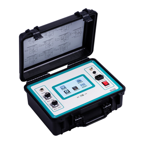
HVTest HT2533 User manual

1
Dear Client
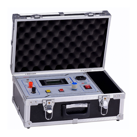
Thank you for Purchasing our HT2533 Pointer Insulation
Resistance Tester. Please read the manual in detail prior to first
use, which will help you use the equipment skillfully.
Our aim is to improve and perfect the company's
products continually, so there may be slight
differences between your purchase equipment and
its instruction manual. You can find the changes in
the appendix. Sorry for the inconvenience. If you
have further questions, welcome to contact with our service
department.
The input/output terminals and the test column
may bring voltage, when you plug/draw the test wire
or power outlet, they will cause electric spark.
PLEASE CAUTION RISK OF ELECTRICAL SHOCK!
Company Address:
T4,No. 41, High-tech 2 Road,East Lake High-tech Development
Zone,Wuhan
Sales Hotline: 86-27- 87457960
After Service Hotline:86-27- 87459656
Fax: 86-27- 87803129
E-mail: [email protected]
Website: www.hvtest.cc

2
SERIOUS COMMITMENT
All products of our company carry one year limited warranty
from the date of shipment. If any such product proves defective
during this warranty period we will maintain it for free. Meanwhile
we implement lifetime service. Except otherwise agreed by
contract.
SAFETY REQUIREMENTS
Please read the following safety precautions carefully to avoid
body injury and prevent the product or other relevant subassembly
to damage. In order to avoid possible danger, this product can only
be used within the prescribed scope.
Only qualified technician can carry out maintenance or repair
work.
--To avoid fire and personal injury:
Use Proper Power Cord
Only use the power wire supplied by the product or meet the
specification of this produce.
Connect and Disconnect Correctly
When the test wire is connected to the live terminal, please do
not connect or disconnect the test wire.
Grounding
The product is grounded through the power wire; besides, the
ground pole of the shell must be grounded. To prevent electric
shock, the grounding conductor must be connected to the ground.

3
Make sure the product has been grounded correctly before
connecting with the input/output port.
Pay Attention to the Ratings of All Terminals
To prevent the fire hazard or electric shock, please be care of
all ratings and labels/marks of this product. Before connecting,
please read the instruction manual to acquire information about the
ratings.
Do Not Operate without Covers
Do not operate this product when covers or panels removed.
Use Proper Fuse
Only use the fuse with type and rating specified for the
product.
Avoid Touching Bare Circuit and Charged Metal
Do not touch the bare connection points and parts of
energized equipment.
Do Not Operate with Suspicious Failures
If you encounter operating failure, do not continue. Please
contact with our maintenance staff.
Do Not Operate in Wet/Damp Conditions.
Do Not Operate in Explosive Atmospheres.
Ensure Product Surfaces Clean and Dry.

4
-Security Terms
Warning: indicates that death or severe personal injury may
result if proper precautions are not taken
Caution: indicates that property damage may result if proper
precautions are not taken.

5
Contents
Overview.............................................................................6
Product Introduction...................................................... 7
1. Performance characteristics.............................................7
2. Technique specifications................................................... 8
Instruction Method....................................................... 10
1. Preparation work...............................................................10
2. Startup test..........................................................................11
3. Instruction of guard terminal........................................ 13
Packing List......................................................................14

6
Overview
With the rapid development of China's power industry,
electrical equipment preventive experiment is an important part in
protecting the safety operation of power system and maintenance.
Insulation diagnosis is an important method to detect insulation
defects or failure. Pointer insulation resistance tester is the special
instrument to measure insulation resistance. JJG662-89
"insulation resistance meter (megger)" approved in May 1990
requires that insulation resistance meter is one of compulsory
verification instruments. Nowadays the development trend of
electrical equipment (such as transformers, generators, etc.) is that
high capacity, high voltage, diversified structure and better seal. So
insulation resistance meter (pointer) itself must have the
characteristics such as large capacity, strong anti-interference ability,
diversified measurement indexes, accurate measurement results,
easy and fast measurement process, easy to carry and so on. The
instrument produced by our company is equipped with ultra-thin
taut suspension meter. It is an ideal tester to measure insulation
resistance of these equipments such as transformer, instrument
transformer, generator, HV motor, power capacitors, power cables,
arrester, etc.

7
Product Introduction
1. Performance characteristics
1) The instrument is used to do insulation test: when the
voltage is 500V, the maximum tested value will up to 20GΩ; when
the voltage is 1000V, the value will up to 40GΩ.
2) When rated output voltage of HT2533 tester continuously
load, the resistance can be as low as 4MΩ/8MΩ/20M, which makes
the instrument can accurately measure lower insulation resistance.
3) Automatic conversion range, dual-scale display, and LED
display corresponding color, it is easy to read.
4) Equipped with ABS plastic casing using, the instrument has
strong anti-interference. Portable design, compact structure, and
attractive appearance.
5) The application of ultra-thin taut suspension meter to the
instrument makes it have strong shock resistance capability.
6) AC/DC dual-use, built-in rechargeable battery and smart
charging module, the whole output power is high (C type).
7) It is an ideal insulation resistance tester to measure these
equipments such as transformer, instrument transformer, generator,
high voltage motor, power capacitor, power cable, arrester, etc.

8
2. Technique specifications
Type no.
HT2533
The output voltage
500V DC
1000V DC
2500V DC
precision
The
temperature
23℃±5℃
Insulation
resistance
1MΩ~20GΩ±5%
2MΩ~40GΩ±5%
5MΩ~100GΩ±5%
The output
voltage
4MΩ~20GΩ0~+10%
8MΩ~40GΩ0~+10%
20MΩ~100GΩ0~
+10%
High voltage short
circuit current
≥1mA
Working power supply
8 AA batteries
Operating temperature
and humidity
-10℃~40℃,Maximum relative humidity 85%
Store temperature and
humidity
-20℃~60℃,Maximum relative humidity 90%
Insulation performance
Circuit between the shell and voltage of 1000 v DC, maximum
2000 m Ω
Compression
performance
When the voltage between the circuit and the housing is 2500V
AC, bear for 1 minute
size
230×190×90mm3(L×W×H)
The weight of the
2kg

9
3. Panel layou

10
The serial
number
The name says
Can work
1
To end(EARTH)
Connect to the housing or ground of the subject device
2
Line side(LINE)
The high voltage output port is connected to the high voltage
conductor of the tested equipment
3
Block end
(GUARD)
High pressure protection ring connected to the test equipment to
eliminate surface leakage Effect of current
4
Double row
calibration lines
The top gear is green:500V/0.2GΩ~20GΩ,
1000V/0.4GΩ~40GΩ,
2500V/1 GΩ~100 GΩ。
The bottom is red:500V/0~400MΩ,
1000V/0~800 MΩ,
2500V/0~2000 MΩ
5
Green light
emitting diode
Read the green (up) scale when lighting
6
Red led
Read the red (down) scale when glowing
7
Mechanical zero
Adjust the position of the mechanical pointer to the infinity scale
8
The band switch
Can realize the output voltage selection, battery detection, power
switch The function such as
9
Test key
Press down to start the test, press down if clockwise rotation can be
locked This button
10
Status display
lamp
Can display high voltage output, power supply working state,
charging state
Instruction Method
1. Preparation work
Note: When you first use the meter, please charge it for 6 hours.
Otherwise the meter does not work. Details refer to “battery charge”
relevant content.
1) Before test, please disconnect measured equipment power
supply and remove all external connections. Let the measured
target ground and discharge 1minute, the measured target with
larger capacitance should discharge at least 2min in order to avoid
electric shock and impact to the measurement results.

11
2) Check whether the pointer on ∞ scale, if not you need to
adjust the mechanical zero screw ⑦.
Note: When adjust the mechanical zero screw, you can
clockwise/ counter-clockwise adjust semi-circle.
3) Use a clean dry cloth to wipe off the surface dirt of measured
object, if necessary, you can wash the casing with gasoline to
eliminate the surface leakage currents to affect test results.
4) Connect HV test lead (red terminal) into line terminal ② , the
other terminal connect to or hang on HV conductor of measured
equipment; Connect green HV test lead to guard terminal ③, the
other terminal connect to HV protection rings of measured
equipment to eliminate the effect of surface leakage currents
(details see "shield terminal (GUARD) instruction" related content).
Connect black test lead to earth terminal (EARTH) ①, the other
terminal connect to the shell of measured device or the ground.
Note: As wiring, pay special attention to the connections of
LINE (red) and GUARD (green), do not let them short circuit.
2. Startup test
1) Adjust selection rotation to connect power supply, if power
supply is normal, the indicator light will become green; if not, it will
become red or yellow.
2) Adjust selection rotation to voltage gear, the instrument will
automatically connect power supply and test the battery capacity

12
for 3 seconds. When the pointer stop in BATT.GOOD area, the
battery is good, otherwise you need replace the battery.
3) Rotate selection rotation to the desired test voltage.
(500V/1000V/2500V).
4) Press or lock “test” key⑩ to start the test. At this time HV
output indicator light above “test” key will glow and built-in buzzer
will sound per 1 second interval which indicating LINE terminal ②
having high-voltage output.
Warning: During test, it is forbidden to touch the front exposed
part of probe to avoid the risk of electric shock.
5) When the green LED glows, read insulation resistance value
on the upper scale (high range); red LED glows, read value on the
lower scale. After test, release “test” key ⑩, the instrument stop test,
wait for a few seconds, and do not immediately remove the probe
from test circuit. At this time the instrument will automatically
release the remaining charge in the test circuit.
Warning: When test is completed or repeatedly do tests,
measured target must be shorted, and then be grounded to
discharge. (Meters also have built-in auto-discharge function, but
need a long time)
6) If you need consecutively do the second test, please refer to
the above 3-5 items.

13
Note: If left unused for a long period, please remove the
batteries from the compartment to prevent battery leakage damage
the instrument.
3. Instruction of guard terminal
When measuring insulation resistance of power cables or
having external electromagnetic interference, in order to eliminate
the effect of surface leakage current and external electromagnetic
interference to the measurement results accuracy, in actual
measurement process, using guard terminal of the instrument to
eliminate leakage current and shielding interference.
For two or more measured objects such as arresters, coupling
capacitor, please wiring as shown in Figure 5. Connect guard
terminal to a flange of measured arrester, so that the interference
current caused by high voltage lines is shielded by guard terminal,
thus prevent interference on the main current. Connect the top
flange of arrester to earth terminal, then let the instrument earth, so
that interfere current can directly be connected to the earth. But the
latter cannot completely eliminated interference.

14
Packing List
1. Instrument host 1
2. Test lead 1
3. The instruction manual 1
4. Certificate 1

15
Table of contents
Other HVTest Test Equipment manuals

HVTest
HVTest HT2672 User manual

HVTest
HVTest HT-802 User manual

HVTest
HVTest HTYSZ-H User manual

HVTest
HVTest TAG-8000 User manual

HVTest
HVTest HTJS-M User manual

HVTest
HVTest HT2670 User manual

HVTest
HVTest HTYX-III User manual

HVTest
HVTest HT2571B User manual
HVTest
HVTest HTJS-V User manual

HVTest
HVTest HTZZ-2A User manual

HVTest
HVTest HTZZ-S10A User manual

HVTest
HVTest HTYZL-H User manual

HVTest
HVTest HTRG-H User manual

HVTest
HVTest HTYB-3H User manual
HVTest
HVTest HT2671 User manual

HVTest
HVTest HTZZ-1A User manual
HVTest
HVTest HT5600 User manual
HVTest
HVTest HTFZ-III User manual

HVTest
HVTest ETCR2000 User manual
HVTest
HVTest HTFZ-HI User manual