I. Product Overview
In order to reduce reactive power loss in power system, shunt capacitor
banks are usually used to improve power factor. In practical application, the
accident rate of capacitor compensation device is relatively high, which is
determined by the characteristics of the working state of capacitor device.
Therefore, it is very important to check the capacitor device regularly and find
capacitor defects early to avoid the expansion of the fault.
Capacitors in the capacitor bank are all in parallel in the field, so the leads
need to be removed when workers measure with a general capacitance meter,
which is a heavy workload and easy to cause wiring errors. The newly
developed capacitor and inductance tester of our company can measure a
single capacitor of a group of parallel capacitors without disconnecting the wire,
and can also measure the inductance and current. The wiring is convenient,
the operation is simple, which reduce the workload of the maintenance
personnel and greatly improves the testing efficiency of the site and provides
security for the normal operation of the power grid.
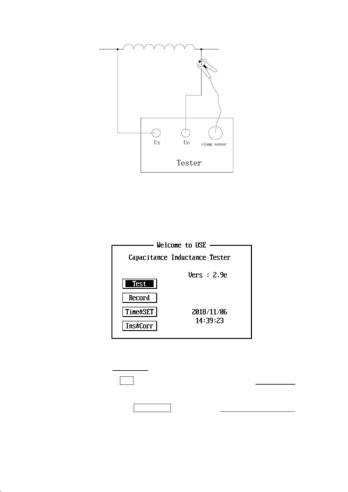
II. Function Features
The instrument can measure the single capacitor of a group of parallel
capacitors without disconnecting the line, which is convenient to test. At
the same time it can also display the measured voltage, current, loss,
capacity, frequency, impedance and other data.
The instrument displays the measured inductance value and also displays
the measured voltage, current, loss, capacity, frequency, impedance and
other data;