HVTest HTZZ-S10A User manual

1
Dear Client
Thank you for Purchasing our HTZZ-S10A Transformer DC
Winding Resistance Tester. Please read the manual in detail prior
to first use, which will help you use the equipment skillfully.
Our aim is to improve and perfect the
company's products continually, so there may be
slight differences between your purchase equipment
and its instruction manual. You can find the changes
in the appendix. Sorry for the inconvenience. If you have further
questions, welcome to contact with our service department.
The input/output terminals and the test column
may bring voltage, when you plug/draw the test wire or
power outlet, they will cause electric spark. PLEASE
CAUTION RISK OF ELECTRICAL SHOCK!
Company Address:
T4,No. 41, High-tech 2 Road,East Lake High-tech Development Zone,
Wuhan
Sales Hotline: 86-27- 87457960
After Service Hotline:86-27- 87459656
Fax: 86-27- 87803129
E-mail: [email protected]
Website: www.hvtest.cc

2
SERIOUS COMMITMENT
All products of our company carry one year limited warranty
from the date of shipment. If any such product proves defective
during this warranty period we will maintain it for free. Meanwhile
we implement lifetime service. Except otherwise agreed by
contract.
SAFETY REQUIREMENTS
Please read the following safety precautions carefully to avoid
body injury and prevent the product or other relevant subassembly
to damage. In order to avoid possible danger, this product can only
be used within the prescribed scope.
Only qualified technician can carry out maintenance or repair
work.
--To avoid fire and personal injury:
Use Proper Power Cord
Only use the power wire supplied by the product or meet the
specification of this produce.
Connect and Disconnect Correctly
When the test wire is connected to the live terminal, please do
not connect or disconnect the test wire.
Grounding
The product is grounded through the power wire; besides, the

3
ground pole of the shell must be grounded. To prevent electric
shock, the grounding conductor must be connected to the ground.
Make sure the product has been grounded correctly before
connecting with the input/output port.
Pay Attention to the Ratings of All Terminals
To prevent the fire hazard or electric shock, please be care of
all ratings and labels/marks of this product. Before connecting,
please read the instruction manual to acquire information about the
ratings.
Do Not Operate without Covers
Do not operate this product when covers or panels removed.
Use Proper Fuse
Only use the fuse with type and rating specified for the product.
Avoid Touching Bare Circuit and Charged Metal
Do not touch the bare connection points and parts of energized
equipment.
Do Not Operate with Suspicious Failures
If you encounter operating failure, do not continue. Please
contact with our maintenance staff.
Do Not Operate in Wet/Damp Conditions.
Do Not Operate in Explosive Atmospheres.
Ensure Product Surfaces Clean and Dry.

4
-Security Terms
Warning: indicates that death or severe personal injury may result
if proper precautions are not taken
Caution: indicates that property damage may result if proper
precautions are not taken.

5
Contents
I. General................................................................................................... 6
II. Performance Index............................................................................ 7
III. Panel Description..............................................................................7
IV. Testing and Operating Method..................................................... 9
V. Precautions....................................................................................... 14
VI. Troubleshooting............................................................................. 15
VII. Transportation and Storage....................................................... 15
VIII. Unpacking and Inspection........................................................ 16
IX. Others................................................................................................ 16

6
Thank you very much for selecting our products!
For your better use of this instrument, you are kindly requested to
read this manual carefully before you use it, so as to understand its
major performances and operation method.
Caution:①It is not allowed to remove the wiring and directly switch off the
power supply during the measurement.
②For the no-load voltage regulating transformer, it is not allowed to
switch the tapping switch during the measurement.
③In case of a sudden power failure during the measurement, this
instrument can discharge automatically. Please do not remove
the wiring immediately. Wait for at least 30 seconds before the
connection can be removed.
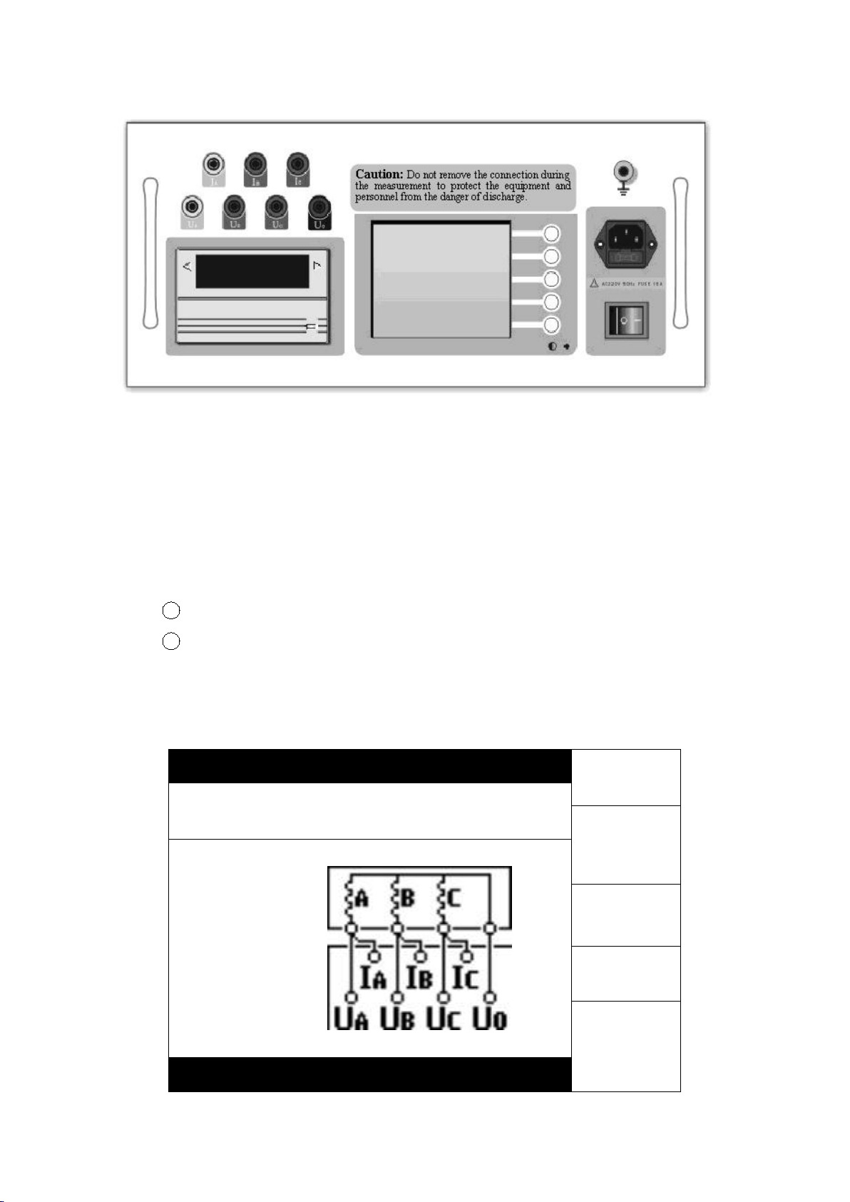
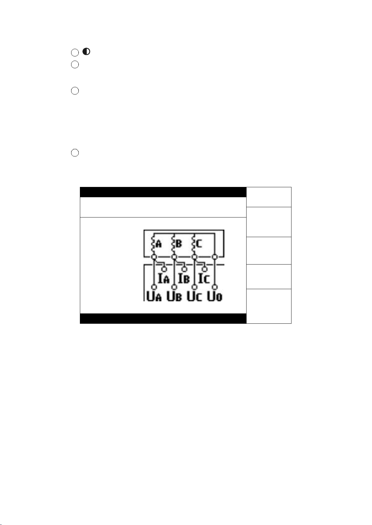
④The three-phase measurement applies to the windings of YN
connection. For the windings of yn connection, since difference
exists between the three-phase and single-phase measurement
results due to the effect of the resistance of the copper bus
connected, the single-phase measurement is recommended.
⑤Caution: The three-phase measurement result doses not include
the resistance value of the neutral lead. Therefore, it is
suggested to at least verify one data using the single-phase
testing method for each phase after completing the
measurement of three-phase resistance value, so as to
determine if the neutral lead is normal.
I. General
This fast DC resistance tester (hereinafter referred to as DC resistance
tester) is the product of the latest generation for measuring the DC resistance
of transformer and is optimally designed for measuring the DC resistance of
the three-phase winding of the large-capacity transformer. It can measure the
DC resistance of the three-phase winding at the same time. In case of the
on-load voltage regulating transformer, it is not required to discharge but to
directly adjust the tapping switch. The measurement time is one third of the
traditional single-phase measurement, greatly shortening the working time and
labor intensity. As the DC resistor tester is provided with large-screen LCD and
the graphical interfaces in Chinese, the operation is visual, clear and easy.

7
Besides, it is provided with panel type printer and large-capacity non-volatile
memory, so the measurement results can be stored and printed out easily.
With good stability in data testing, speediness and perfect repeatability, it is the
best choice for the on-site measurement of DC resistance of transformer.
II. Performance Index
Testing current
Single phase: 1A 5A 10A 20A
Three phase: 1A 5A 10A
Measurement
scope
Single phase: 1A 10 mΩ~20Ω 5A 1 mΩ~4Ω
10A 1 mΩ~2Ω 20A 1 mΩ~1Ω
Three-phase: 1A 10 mΩ~6Ω (each phase)
5A 1 mΩ~1Ω (each phase )
10A 1 mΩ~0.6Ω (each phase )
Measurement
accuracy
± (0.2%Full span ± 2 words )
Maximum
resolution
0.1μΩ
Data storage
capacity
150 groups
Power supply
AC 220V±22V, 50Hz±2 Hz
Working
environment
Ambient temperature: 0℃~40℃ Relative humidity :≤80%RH
Overall
dimensions
440*205*455mm 3
The weight of
the
17kg
III. Panel Description
The panel of DC resistance tester is shown in the figure below:

8
①Ia Ib Ic: The dc current output. In case of single phase or two-phase
measurement, Ia and Ib are current output.
②Ua Ub Uc Uo: The input of measuring voltage. In case of single-phase
measurement, Ua and Ub are voltage input. In case of two-phase
measurement, Ua and Ub are the voltage input of the first channel; Uc and Uo
are the input of the second channel.
3Panel printer: Prints the output measurement results.
4LCD: displays the measurement results and operation prompting
information, with the function definition of the five multi-function key-presses
under the current state given in the key definition zone on the right, as shown
in the figure below :
2007.01.01
Set
Measurement mode: three phase
Measuring current: 10 A
View
Wiring Diagram
Mode
Current
Measure
1 4 : 0 2 : 5 1

9
5: Contrast regulation of LCD
6Power socket: the power input of the complete unit, with built-in fuse
tube. The fuse tube is 10A/250V.
7Earthing pole: The earthing pole on the enclosure of the complete unit.
Make sure that it is reliably grounded during measurement.
IV. Testing and Operating Method
1Connect with the power source and earth wire, switch on the power
supply to enter into the initial interface, as shown in the figure below:
2 0 0 7 . 0 1 . 0 1
Set
Measurement method: Three phase
Testing current: 10 A
View
Wiring Diagram
Mode
Current
Measure
1 4 : 0 2 : 5 1
“Set” key-press: Set the current date and time.
“View” key-press: View the data stored, including measurement results,
testing date, tapping number and etc.
“Mode” key-press: Sets the measurement mode, including “Single Phase”,
“Two-phase” and “Three-phase”, besides, corresponding schematic wiring
diagram will be displayed in the zone of “Schematic Wiring Diagram” as the
reference for actual wiring.
“Current” key-press: Sets the size of testing current. In case of the
single-phase or two- phase measurement, the current 1A, 5A, 10A and 20A
can be selected. You may select suitable measuring current by referring to the
related parameters listed in the technical indicators as the reference.
“Measure” key-press: After the testing wire is connected and the

10
measuring current is selected, press “Measure” key-press to start the test.
2Single-phase measurement:
The wiring method is shown in the figure below (Taking the measurement
as of RAB an example):
After the winding under test is wired and the suitable measuring current is
selected, press the “Measure” key-press to allow the tester to enter into its
measuring state and to start to supply power to the winding, and then it enters
into the interface as follows:
2 0 0 7 . 0 1 . 0 1
Tap
R
0. 0 A
Store
The battery is charging, please wait a moment!
Current tap: 01
Print
Re-test
Exit
1 4 : 0 2 : 5 1
At this time, the current of the winding starts to increase. If the charging
progress strip and the current display value stand still for a long time, it
indicates that the value of the resistance value to be measured is probably
beyond the measuring scope of the current, so it is not able to reach its set
value. At this time, press “Exit” key-press to return and re-select the current
and retry. When the set value is reached, it becomes constant. Then, enter into

11
the next interface.
2 0 0 7 . 0 1 . 0 1
Tap
R
351.2mΩ
Store
Current tap: 0 1
Print
Re-test
Exit
1 4 : 0 2 : 5 1
Now, the dc resistance tester starts to display the resistance value of the
winding under test and such value gradually becomes stable. At this time,
press the Tap button to adjust and set the current tap value or winding name so
as to mark the measurement result. After the Tap button is pressed down, the
multi-functional key on the right becomes “▲”“▼”“ ”“OK” and “Cancel”, and
the tap setting dialogue box is ejected. After setting, press “OK” button to save
it and press “Cancel” button to modify it. Then, press “Store” and “Print” button
to save or print the measurement result. In case of any doubt about the data,
press “Retest” button to carry out the measurement and calculation again.
When measuring the on-load voltage changing transformer, after the
testing data of one tapping position becomes stable, the on-load tapping
switch may be switched to the next tapping position, without discharging to
conduct the measurement over again. At this time, the resistance value of the
winding will change gradually until it becomes stable. You may also press
“Re-test” button to quickly refresh the data. Repeat the above-mentioned
procedure until all the tapping tests are completed.
③Three-phase measurement:
The three-phase measurement applies to the windings of YN star

12
connection with neutral lead. For the windings of yn connection, since
difference exists between the three-phase and single-phase measurement
results due to the effect of copper bus connected, single-phase measurement
is recommended.
The three-phase wiring is shown in the figure below:
After the winding under test is wired and the suitable measuring current is
selected, press the “Measure” key-press to allow the tester to enter into its
measuring state and to start to supply power to the winding, and then it enters
into the interface as follows:
2 0 0 7 . 0 1 . 0 1
Tap
A
0 . 0 A
B
0 . 0 A
Store
C
0 . 0 A
The battery is charging, please wait a moment !
Current tap: 0 1
Print
Re-test
Exit
1 4 : 0 2 : 5 1
At this time, the current of the winding starts to increase. If the charging
progress strip and the current display value stand still for a long time, it
indicates that the value of the resistance value to be measured is probably
beyond the measuring scope of the current, so it is not able to reach its set
Yellow
Green
Red
Black

13
value. At this time, press “Exit” key-press to return and re-select the current
and retry. When the set value is reached, it becomes constant. Then, enter into
the next interface.
2 0 0 7 . 0 1 . 0 1
Tap
A
351.2mΩ
B
350.6mΩ
Store
C
351.6mΩ
Imbalance rate: 0 0 . 2 8 %
Current tap : 0 1
Print
Re-test
Exit
1 4 : 0 2 : 5 1
Now, the dc resistance tester starts to display the resistance value of each
phase. With the resistance value of each phase becoming stable, the
imbalance rate will gradually decrease. Under such state, the “Tap” button may
be pressed to adjust and set the current tap value or winding name so as to
mark the measurement result. After the “Tap” button is pressed down, the
multi-functional key on the right becomes “▲”“▼”“ ”“OK” and “Cancel”, and
the tap setting dialogue box is ejected. After setting, press the “OK” button to
save it and press the “Cancel” button to modify it. Then, press “Store” and
“Print” button to save or print the measurement results. In case of any doubt
about the data, press “Retest” button to carry out the measurement and
calculation again. The maximum display scope of the imbalance rate is 50%. If
such scope is exceeded, only “50%” will be display.
When measuring the on-load voltage changing transformer, after the
testing data of one tapping position becomes stable, the on-load tapping
switch may be switched to the next tapping position, without discharging to
conduct the measurement over again. At this time, the resistance value and

14
imbalance rate of each phase will change gradually until they become stable.
You may also press “Re-test” button to quickly refresh the data. Repeat the
above-mentioned procedure until all the tapping tests are completed.
Upon the completion of the measurement, press the “Exit” key to
end the measurement. At this time, the DC resistance tester starts to
discharge and the display gives corresponding discharge indication and
the buzzer rings. After the discharge is completed and the tester returns
to the initial interface, the measurement wiring may be removed.
V. Precautions
1When measuring the no-load voltage changing transformer, be sure to
exit from the discharge before switching the tapping switch. Do not switch the
tapping switch before the discharge is completed according to the discharge
indication.
2Do not remove the wiring during the measurement.
3If the charging progress strip and the current display value stand still
for a long time, it indicates that the value of the resistance value to be
measured is probably beyond the measuring scope of the current, so it is not
able to reach its set value. At this time, press the “Exit” button to return and
reselect the current to retry.
4When replacing the fuse tube and the fittings, please use the same
model as this instrument.

15
VI. Troubleshooting
Fault phenomenon
Cause analysis
Solution
Remarks
There is no display
after switching on.
1) The power supply
is not switched on.
Switch on the
power supply
Replace with the
fuse tube of the
same model. Do
not substitute it
with the fuse
tubes of other
models.
2) The 10A fuse
tube of the
instrument is not
properly fitted or the
circuit is open.
Fit or replace the
fuse tube
There is no current
output
1) The equipment to
be tested is
open-circuited
Check the
equipment and
eliminate the
faults.
2) The test circuit is
open-circuited.
Check the test
circuit and
eliminate the
open-circuit fault.
VII. Transportation and Storage
■ Transportation
When transporting the equipment, it is suggested using the instrument
packing wood boxes and damping materials of our company to avoid any
unnecessary damage and loss during the transportation.
Do not stack the equipment if it is not transported in a wood box. If the
instrument packing box of our company is used, the maximum permissible
stacking layers are two layers.
The equipment shall be transported with the instrument panel facing
upward.
■ Storage
The equipment shall be stored in the dry, dust-free and well-ventilated
room without corrosive gas. Do not stack the equipment if it is not packed in
the wood box.
The equipment shall be stored with its panel facing upward. Besides,
damproof materials shall be provided at its bottom to protect it from dampness.

16
VIII. Unpacking and Inspection
■ Precautions for unpacking
Before unpacking, make sure that the arrow on the package of the
equipment is upward. When unpacking, do not knock it by force, otherwise the
equipment will be damaged. Unpack and take out the equipment. To protection
the environment, keep the equipment package and damping materials so that
you can use them for future transportation and storage.
■ Inspection content
Take out the equipment and check and count the equipment and fittings
against the packing list. In case of any shortage, please make contact with our
company. We will give serve you as soon as possible.
IX. Others
The warranty period for the whole set of this product is one year and
“Three-guarantees” (repair, return and exchange guarantees) is implemented.
Maintenance service can be provided throughout its service life. For any
quality problem of the equipment within the warranty period, free maintenance
will be provided. For the damages due to the improper operation or
carelessness of the user, services will be provided at favorable prices.
We are looking forward to your precious suggestions about our product. If
the address and contact information of your company are changed, please
keep us informed so that we can serve you in good time.
Table of contents
Other HVTest Test Equipment manuals

HVTest
HVTest HT5600 User manual

HVTest
HVTest HTZZ-1A User manual

HVTest
HVTest HTFZ-III User manual

HVTest
HVTest HTJY-80S User manual

HVTest
HVTest HTRG-H User manual

HVTest
HVTest ETCR2000 User manual

HVTest
HVTest HTJS-M User manual

HVTest
HVTest HTZZ-5A User manual

HVTest
HVTest HT-802 User manual

HVTest
HVTest HTFZ-HI User manual

HVTest
HVTest HT2670 User manual

HVTest
HVTest HT2671 User manual

HVTest
HVTest HTYZL-H User manual

HVTest
HVTest HTYX-III User manual

HVTest
HVTest HTYSZ-H User manual

HVTest
HVTest HTYB-3H User manual

HVTest
HVTest HT2533 User manual

HVTest
HVTest TAG-8000 User manual

HVTest
HVTest HTJS-V User manual

HVTest
HVTest HT2571B User manual