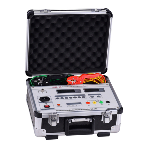
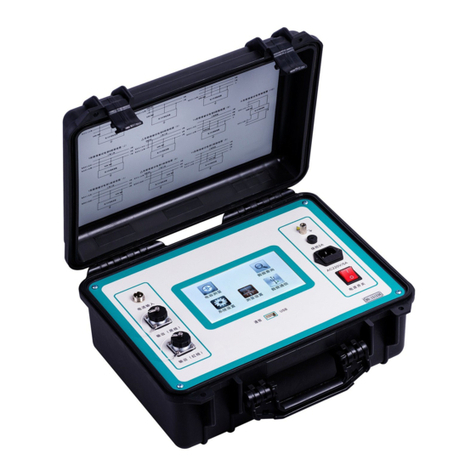
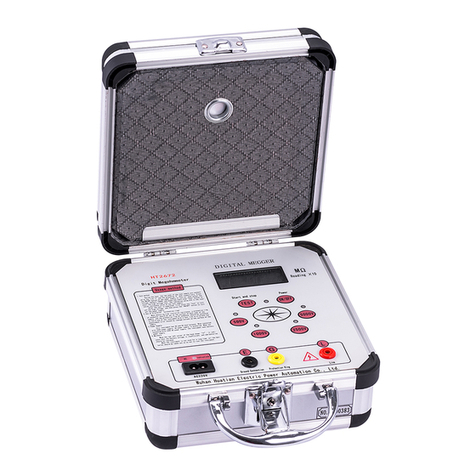
HVTest HTYB-3H User manual

Dear Client
Thank you for Purchasing our HTYB-3H Zinc Oxide Arrester Tester.
Please read the manual in detail prior to first use, which will help you use the
equipment skillfully.
Our aim is to improve and perfect the company's products
continually, so there may be slight differences between your
purchase equipment and its instruction manual. You can find
the changes in the appendix. Sorry for the inconvenience. If
you have further questions, welcome to contact with our service
department.
The input/output terminals and the test column may bring
voltage, when you plug/draw the test wire or power outlet, they
will cause electric spark. PLEASE CAUTION RISK OF
ELECTRICAL SHOCK!
Company Address:
T4,No. 41, High-tech 2 Road,East Lake High-tech Development Zone,Wuhan
Sales Hotline: 86-27- 87457960
After Service Hotline:86-27- 87459656
Fax: 86-27- 87803129
E-mail: [email protected]
Website: www.hvtest.cc

SERIOUS COMMITMENT
All products of our company carry one year limited warranty from the date
of shipment. If any such product proves defective during this warranty period
we will maintain it for free. Meanwhile we implement lifetime service. Except
otherwise agreed by contract.
SAFETY REQUIREMENTS
Please read the following safety precautions carefully to avoid body injury
and prevent the product or other relevant subassembly to damage. In order to
avoid possible danger, this product can only be used within the prescribed
scope.
Only qualified technician can carry out maintenance or repair work.
--To avoid fire and personal injury:
Use Proper Power Cord
Only use the power wire supplied by the product or meet the specification
of this produce.
Connect and Disconnect Correctly
When the test wire is connected to the live terminal, please do not
connect or disconnect the test wire.
Grounding
The product is grounded through the power wire; besides, the ground
pole of the shell must be grounded. To prevent electric shock, the grounding
conductor must be connected to the ground.
Make sure the product has been grounded correctly before connecting

with the input/output port.
Pay Attention to the Ratings of All Terminals
To prevent the fire hazard or electric shock, please be care of all ratings
and labels/marks of this product. Before connecting, please read the
instruction manual to acquire information about the ratings.
Do Not Operate without Covers
Do not operate this product when covers or panels removed.
Use Proper Fuse
Only use the fuse with type and rating specified for the product.
Avoid Touching Bare Circuit and Charged Metal
Do not touch the bare connection points and parts of energized
equipment.
Do Not Operate with Suspicious Failures
If you encounter operating failure, do not continue. Please contact with
our maintenance staff.
Do Not Operate in Wet/Damp Conditions.
Do Not Operate in Explosive Atmospheres.
Ensure Product Surfaces Clean and Dry.

-Security Terms
Warning: indicates that death or severe personal injury may result if proper
precautions are not taken
Caution: indicates that property damage may result if proper precautions
are not taken.

HTYB-3H Zinc Oxide Lightning Arrester Tester
Table of Contents
I. Overview:.....................................................................................................................1
II. Structure Diagram for Instrument Panel:................................................................. 1
III. Main Technical Indexes:............................................................................................1
IV. Wiring Diagrams:.......................................................................................................1
V. Instrument Operation:............................................................................................... 2
VI. Measurement Principle and Data Analysis:............................................................ 4
VII. Precautions: ..........................................................................................................5
VIII. Packing List of Instrument:.....................................................................................6

1
Metal Oxide Arrester Tester
Operating Manual
I. Overview:
The metal oxide arrester tester is used for the measurement and analysis of metal oxide
arrester [MOA] leakage. It is mainly used for measuring the resistive current to analyze the degree
of zinc oxide aging and damp. The field charged test shall conform to Electric Power Industry
Standard of the People's Republic of China DL474.5-92 Guide for Insulation Test on Site - Lightning
Arrester Tests. The metal oxide arrester tester can be also used for factory and acceptance tests.
II. Structure Diagram for Instrument Panel:
Figure 1
III. Main Technical Indexes:
Range of reference voltage input (peak): 10V-200V Customizable (0-250V)
Measurement range of full leakage current (peak): 100uA-8mA Customizable (0-20mA)
Measurement range of resistive current (peak): 100uA-8mA Customizable (0-20mA)
Measurement range of capacitive current (peak): 100uA-8mA Customizable (0-20mA)
Measurement range of angle: 0°~ 90°
Power consumption: 4W
System measurement accuracy: (reading 5% + 5 words) (not more
than 2mA for harmonic current)
AC power supply: AC 220V 10%,50Hz 1%
IV. Wiring Diagrams:
1. Laboratory wiring diagram
Precautions: the lower end of the arrester and the ground terminal are marked on the current
line. Please wire according to the marks.

2
Figure 2
In this method, the adjustable high voltage power supply shall be provided, the voltage
signal input is connected to the end of the measuring meter for the testing transformer, one end
of the metal oxide arrester is connected to the high voltage, the other end is grounded through
the protector to be connected with the ground of the instrument and the ground of the high
voltage power supply. The AC signal input is connected to the lower end of the arrester and the
ground.
Boosting value: ≤10KV/1.5 ≥35KV/
3
2. Online wiring diagram (live test)
Figure 3
In the online measurement, the voltage signal input is connected to the secondary side of
PT located at the same phase as the measured arrester, the current signal input is connected to
two ends of the arrester counter, and the ground terminal of the instrument is connected to the
lower end of the counter and is connected with the ground.
Refer to the above wiring method for correct wiring according to the field requirements.
V. Instrument Operation:
1. Connect the line and the instrument power supply, and turn on the power supply, then the
screen displays as shown in Figure 4.

3
Arrester characteristics tester
System Settings
Data Measurement
Data View
Instrument Calibration
Time Calibration
↑↓ Move YEnter NEsc
Figure 4 Main Menu
2. Click System Settings to display the menu as shown in Figure 5:
Arrester characteristics tester
Compensation Angle +0.000
Transformation Ratio 01000
Device No 0000-A
↑↓ Move YEnter NEsc
Figure 5 System Settings Menu
In this menu, you can set the transformation ratio and the compensation angle.
The entry of digits is - 1 2 3 4 5 6 7 8 9 0. Cycle. The transformation ratio cannot be
negative, the first digit of the compensation angle is only -, and other entry is wrong. One
decimal point is only used between the data.
↑: cycle the digit. ↓: move to the right. After the digits are entered, press Return to save.
* Note the correct algorithm of the transformation ratio:
Determination method for transformation ratio of testing transformer: the transformation
ratio herein should be turns ratio or voltage ratio of high voltage winding and measuring
instrument winding. For example, for the testing transformer with AC output rated voltage of
50KV, the rated voltage of the measuring instrument winding is usually 100V, so the
transformation ratio is 50KV/100V=500. Determination method for online transformation ratio:
for example, the transformation ratio of 110KV arrester is (110KV/ )/(100KV/ )=1100.
*Algorithm of input compensation angle:
When the compensation angle is 0, firstly measure the angle φ{φA and φC} for phase A and
phase C, and use {φC-φA}/2=compensation angle, wherein φA is positive, and φC is negative.
3. Click the menu “Data Measurement” to display the menu as shown in Figure 6:
Figure 6 Data Test Main Menu
Compensation angle: for the stored data, the compensation angle can be modified, but the
modified value only influences the currently displayed/printed data and cannot be saved.
Transformation ratio: PT or transformation ratio of testing transformation, the displayed test
0000-A Arrester Test Interface
Full V
0.000KV
Full I
0.000mA
Fund V
0.000KV
Res I
0.000mA
Cap I
0.000mA
Res Fund I
0.000mA
Freq
50.00Hz
Res I3
0.000mA
A Power
0.000W
Res I5
0.000mA
R Power
0.000W
Res I7
0.000mA
Ratio
0.000
Res IMax
0.000mA
Angle
0.000
Diff Phase
0.00
Wave Save Print Esc
3
3

4
voltage U is the product of input reference voltage Uref and K. As K does not affect the
measurement of angle or current magnitude, it can be set to 1, directly displayed as U1. Note that
the correct measurements cannot be obtained when there is no U1 input. For the stored data, the
voltage transformation ratio can be modified, but the modified value only influences the currently
displayed/printed data and cannot be saved.
Test phase difference: the phase difference of the leading fundamental voltage at the
fundamental current includes the compensation angle. MOA performance can be evaluated
according to the angle, and shall be evaluated by deducting the interference angle in case of
interphase interference.
Waveform display Full voltage waveform
Full current waveform
Resistive current waveform
4. Click “Data View” to display the menu as shown in Figure 7:
0000-A January 5, 2015 08:08:08 001-001
Full V
0.000KV
Full I
0.000mA
Fund V
0.000KV
Res I
0.000mA
Cap I
0.000mA
Res fund I
0.000mA
Freq
50.00Hz
Res I3
0.000mA
A Power
0.000W
Res I5
0.000mA
R Power
0.000W
Res I7
0.000mA
Ratio
0.000
Res IMax
0.000mA
Angle
0.000
Diff Phase
0.00
↑Prev ↓Next YPrint NEsc
Figure 7 Data View Main Menu
5. Printout
To print, directly operate according to the screen prompt. In order to facilitate the user to
analyze and save the test data, the instrument saves 100 sets of test data for the user to print.
(After measurement, the user can save the data as required.)
6. Instrument calibration
Enter the password to enter the instrument calibration. Enter the instrument calibration
only when the instrument accuracy is wrong. Do not enter at other times.
7. Time calibration
January 5, 2015 08:08:08
↑ Change digits ↓ Move cursor
VI. Measurement Principle and Data Analysis:
The instrument inputs PT secondary voltage as a reference signal and inputs MOA current
signal to obtain the fundamental voltage U1, the fundamental current peak and the current and
voltage angle Φ (Figure 8) by Fourier transformation. The voltage cophase component is resistive
current fundamental value (Ir1p), and the quadrature component is apacitive current fundamental
value (Ic1p):
Ir1p=Ix1pCOSΦ Ic1p=Ix1pSINΦ

5
Considering δ=90°, Φ is equivalent to the dielectric loss angle, so it is very simple to evaluate
MOA with Φ; Φ is 81° to 86° if there is no interphase interference. According to the requirement
that the resistive current cannot exceed 25% of the total current, Φ cannot be less than 75.5°. refer
to the following table for the segmented evaluation of MOA performance:
Φ
<75°
75°~77
°
78°~80°
81°~83°
84°~88°
>89°
Performance
Very poor
Poor
Average
Good
Excellent
With interference
In fact, consider in case of Φ<80°
Figure 8 Projection Method Figure 9 Interphase Interference of In-line Arresters
2.2 Interphase Interference
In the field measurement, the intermediate B phase of the in-line arresters impacts the
leakage currents A and C through the stray capacitance: A phase φ is reduced by 2° or so and the
resistive current is increased; C phase φ is reduced by 2° or so and the resistive current is reduced
to the negative; B phase is not changed. This phenomenon is called interphase interference (Figure
9).
2.3 Performance Evaluation of MOA with Interference
1. It is suggested that the same phase PT secondary voltage should be used to measure the
same phase MOA current. The compensation angle is 0, and the interphase interference is not
considered in the measurement. For the laboratory measurement, the compensation angle (Φ0=0)
should not be used.
The interphase interference can be considered when MOA performance is evaluated. Based on
B phase Φ, the reduced value of A phase Φ is basically equal to the increased value of C phase Φ
according to the symmetry of interphase interference, so as to evaluate the interphase
interference angle. For example, if A phase Φ is 2° less than the normal value, and C phase Φ is 3°
more than the normal value, the interphase interference will be approximately 2.5°. When MOA
performance is evaluated, A is +2.5°, B phase Φ is not changed, and C phase Φ is 2.5°.
2. If the interphase interference is considered in the measurement, the compensation angle
can be set for A/C phase and is added to Φ. Considering the interphase interference of B phase to
A/C phase is symmetrical, if the angle Φca for the leading Ia of Ic is measured, A/C phase will be
respectively compensated, the same phase PT secondary voltage will be used to measure the same
phase MOA current, and the above compensation angle will be added. MOA performance will be
evaluated directly according to Φ.
VII. Precautions:
1. When measure the reference voltage from PT or the measuring end of the testing
transformer, carefully check wiring to avoid the PT secondary or test voltage short circuit.
2. Be careful not to wrongly connect the current and voltage sampling lines in the connecting
process.
3. In the laboratory experiment, the high voltage power supply cannot use the series excitation
testing transformer.
A phase
B phase
C phase
Stray
capacitance
With
interference
With
interference
Without
interference
Without
interference

6
VIII. Packing List of Instrument:
1. Host 1
2. Voltage signal sampling line 1
3. Current signal sampling line 1
4. Power line 1
5. Fuse 2
6. Special protector 1
7. Operating manual 1
8. Product certificate 1
Appendix:
I. Main Problems of Metal Oxide Arrester in Operation
1. As the series gap of the the metal oxide arrester is eliminated, the metal oxide arrester
withstands the system voltage for a long time, and the current flows through it. The active
component valve disc in the current heats to cause the change to volt-ampere characteristics.
After long-term action, the valve disc will be aged, even thermally broken down.
2. If the metal oxide arrester is used under the surge voltage, the valve disc will be aged under
the action of surge voltage energy.
3. If the inside of the metal oxide arrester is affected with damp or its insulation performance
is poor, the power current and the power consumption will be increased, and the internal
discharge will be caused in severe case.
4. If the metal oxide arrester is polluted by rain, snow, condensation or dust, the radial
discharge will be caused by the large potential difference between the internal valve disc and the
external insulator due to the distribution difference of internal and external voltages.
II. Tasks Completed by the Instrument
To judge whether the valve disc of the metal oxide arrester is aged or affected with damp,
usually observe the change of resistive leakage current flowing through the zinc oxide valve disc in
the normal operation, i.e., observe whether the resistive current is increased as the judgment
basis.
III. Main Failures of the Instrument
1. The metal oxide arrester has thermal breakdown
The final reason for the thermal breakdown of the metal oxide arrester is that its heating
power is larger than the heat dissipation power. The heating power of the zinc oxide valve disc
depends on its current and voltage (the current is the active component of the current flowing
through the valve disc).
2. The metal oxide arrester is internally affected with damp
Untight sealing will cause the arrester to be internally affected with damp, or internal water
immersion in the installation will also cause the total current of the arrester to be increased under
the voltage. If the arrester is affected with damp to a certain degree, the discharge will occur along
the surface of the zinc oxide valve disc or the inner wall surface of the insulator to cause the
explosion of arrester.
The increase of total current caused by the damp of metal oxide arrester results from the
increase of resistive leakage current. Whether the arrester is affected with damp can be judged by
detecting the amplitude of angle variation.
To sum up, the above failures can be reflected by the change of resistive leakage current. If

7
you understand the change to the resistive leakage current of the metal oxide arrester, you can
predict whether the above failures occur.
Table of contents
Other HVTest Test Equipment manuals

HVTest
HVTest HTZZ-5A User manual

HVTest
HVTest HT2533 User manual

HVTest
HVTest HTJY-80S User manual

HVTest
HVTest HTZZ-1A User manual

HVTest
HVTest HT2672 User manual

HVTest
HVTest ETCR2000 User manual

HVTest
HVTest TAG-8000 User manual

HVTest
HVTest HTZZ-2A User manual

HVTest
HVTest HTFZ-HI User manual

HVTest
HVTest HTJS-V User manual

HVTest
HVTest HT2670 User manual

HVTest
HVTest HT5600 User manual

HVTest
HVTest HTYX-III User manual

HVTest
HVTest HTFZ-III User manual

HVTest
HVTest HTYSZ-H User manual

HVTest
HVTest HTYZL-H User manual

HVTest
HVTest HT2571B User manual

HVTest
HVTest HTRG-H User manual

HVTest
HVTest HTZZ-S10A User manual

HVTest
HVTest HTJS-M User manual