HVTest HT-802 User manual

1
Dear Client
Thank you for Purchasing our HT-802 Protection Relay Test Set. Please
read the manual in detail prior to first use, which will help you use the equipment
skillfully.
Our aim is to improve and perfect the company's products
continually, so there may be slight differences between your
purchase equipment and its instruction manual. You can find the
changes in the appendix. Sorry for the inconvenience. If you
have further questions, welcome to contact with our service department.
The input/output terminals and the test column may bring
voltage, when you plug/draw the test wire or power outlet, they will
cause electric spark. PLEASE CAUTION RISK OF ELECTRICAL
SHOCK!
Company Address:
T4,No. 41, High-tech 2 Road,East Lake High-tech Development Zone,Wuhan
Sales Hotline: 86-27- 87457960
After Service Hotline:86-27- 87459656
Fax: 86-27- 87803129
E-mail: [email protected]
Website: www.hvtest.cc

2
SERIOUS COMMITMENT
All products of our company carry one year limited warranty from the date
of shipment. If any such product proves defective during this warranty period we
will maintain it for free. Meanwhile we implement lifetime service. Except
otherwise agreed by contract.
SAFETY REQUIREMENTS
Please read the following safety precautions carefully to avoid body injury
and prevent the product or other relevant subassembly to damage. In order to
avoid possible danger, this product can only be used within the prescribed
scope.
Only qualified technician can carry out maintenance or repair work.
--To avoid fire and personal injury:
Use Proper Power Cord
Only use the power wire supplied by the product or meet the specification of
this produce.
Connect and Disconnect Correctly
When the test wire is connected to the live terminal, please do not connect
or disconnect the test wire.
Grounding

3
The product is grounded through the power wire; besides, the ground pole
of the shell must be grounded. To prevent electric shock, the grounding
conductor must be connected to the ground.
Make sure the product has been grounded correctly before connecting with
the input/output port.
Pay Attention to the Ratings of All Terminals
To prevent the fire hazard or electric shock, please be care of all ratings
and labels/marks of this product. Before connecting, please read the instruction
manual to acquire information about the ratings.
Do Not Operate without Covers
Do not operate this product when covers or panels removed.
Use Proper Fuse
Only use the fuse with type and rating specified for the product.
Avoid Touching Bare Circuit and Charged Metal
Do not touch the bare connection points and parts of energized equipment.
Do Not Operate with Suspicious Failures
If you encounter operating failure, do not continue. Please contact with our
maintenance staff.
Do Not Operate in Wet/Damp Conditions.
Do Not Operate in Explosive Atmospheres.
Ensure Product Surfaces Clean and Dry.

4
-Security Terms
Warning: indicates that death or severe personal injury may result if proper
precautions are not taken
Caution: indicates that property damage may result if proper precautions are
not taken.

5
Contents
CHAPTER 1 INSTRUMENT CHARACTERISTICS AND TECHNIQUE PARAMETERS.................................. 6
Section 1 Main characteristics..................................................................................................... 6
Section 2 Technique parameters.................................................................................................7
CHAPTER 2 HARDWARE STRUCTURE..................................................................................................9
Section 1 hardware components................................................................................................. 9
Section 2 Instruction of panel.....................................................................................................11
CHAPTER 3 USE THE TESTER........................................................................................................... 13
Section 1 General Rules for Use............................................................................................... 13
Section 2 Procedures of starting up/shutdown........................................................................14
Section 3 relay protection test item........................................................................................... 15
CHAPTER 4 INTRODUCTION OF SOFTWARE OPERATION.................................................................18
Section 1 Software and driver installation................................................................................18
Section 2 AC Test........................................................................................................................ 19
Section 3 DC Test........................................................................................................................ 25
Section 4 Frequency Test...........................................................................................................27
Section 5 Synchronous Test...................................................................................................... 29
Section 6 Current&Voltage Test................................................................................................ 32
Section 7 Differential Test...........................................................................................................33
Section 8 Impedance Characteristic......................................................................................... 41
Section 9 Harmonic Test.............................................................................................................43
Section 10 Power Direction Test............................................................................................... 44
Section 11 Impedance Test........................................................................................................45
Section 12 Zero Sequence Protection......................................................................................48
Section 13 Group Test................................................................................................................ 50
Section 14 State Sequence Test............................................................................................... 54
Section 15 Inverse Time Overcurrent Relay Test...................................................................56
Section 16 Differential Relay Test............................................................................................. 57
Section 17 Intermediate relay.................................................................................................... 59
Section 18 Frequency Variation Test........................................................................................61
Section 19 Failure Recurrence.................................................................................................. 62
Section 20 System Vibration...................................................................................................... 63
Section 21 Measuring Instruments............................................................................................65
Section 22 BZT Test.................................................................................................................... 66
BEGINNER’S GUIDE......................................................................................................................... 74
APPENDIX A DRIVER INSTALLATION INSTRUCTIONS.......................................................... 74
APPENDIX B COMMON FAILURE EXCLUSION OF USB COMMUNICATION......................76
APPENDIX C PACKING LIST.......................................................................................................... 77
6
Chapter 1 Instrument characteristics and
technique parameters
Section 1 Main characteristics
1. Meets all the requirement of field tests. This tester with standard 4 phase voltage, 3
phase current output, voltage 125V/phase, current 40A/phase, 3 phases in parallel can up to
120A. Digital Signal Processor Microcomputer. Not only test the traditional relays and
protectors, but also test the modern micro computer replays, special for transformer
differential protection and transfer equipments
2. All technical indicators fully meet the standard DL/T624-1997: Technical condition of
the relay computer test device.
3. Classic Windows XP operating interface, friendly man-machine interface, easy and
fast to operate; High-performance embedded industrial control computer and 8.4 inch 8.4 -
inch resolution of 800 × 600 TFT true color display which provides rich visual information,
includes the current working condition and all kinds of help information.
4. The Windows XP system comes with the restore function; avoid system crashes
caused due to illegal shutdown, or malfunction, etc.
5. Equipped with ultra-thin industrial keyboard and optical mouse, complete a variety of
operations using keyboard or mouse the same as ordinary PC.
6. The main control board is DSP + FPGA architecture, 16 bit DAC output, generates
high - density sine wave 2000 points each circle to fundamental wave, which greatly improve
the wave quality and the accuracy of the test instrument.
7. Using high-fidelity linear amplifier. Both to ensure the accuracy of a low current, but
also guarantee the stability of the high current.
8. USB directly connect with PC, without any adapter cable, easy to use.
9. Can be connected to a laptop computer (optional).Laptop computers and industrial
machines use the same software, no need to re-learn the methods of operation.

7
10. With GPS synchronization test function. The device can be built-in GPS
synchronization card (optional) connects with PC by RS232; people can do remote
synchronization swap test for the two testers.
11. With a separate DC auxiliary voltage source, output voltage 110V(1A),220V(0.6A),
provides relays or protective devices which require DC power.
12. The software with self calibrating function, which avoid to calibrate accuracy by
adjusting relays after open the case, greatly improve the stability of the accuracy.
Section 2 Technique parameters
1. AC current source
Phase current output (effective value): 0~40A/phase, accuracy 0.5%.
3 phase parallel current output (effective value): 0~120A/3 phase parallel output in same
phase
Phase current working value for allowed long time (effective value): 10A
Maximum output power of each Phase: 420VA
Maximum output power of 3 parallel current: 900VA
Maximum permitted work time of 3 parallel current: 10S
Frequency range: 0~1000Hz; accuracy: 0.001Hz
Harmonic time: 2~20; phase: 0--360°; accuracy: 0.1°
2. DC current source
Current output: 0~±30A / phase, accuracy:0.5%
3. AC voltage source
Phase voltage output (effective value): 0~125V/phase, accuracy: 0.5%
Line voltage output (effective value): 0~250V
Phase voltage / Line voltage output power: 75VA / 100VA
Frequency range: 0~1000Hz accuracy: 0.001Hz
Harmonic time: 2~20; phase: 0--360°; accuracy: 0.1°
4. DC voltage source

8
Phase voltage output range: 0~±150V accuracy: 0.5%
Line voltage output range: 0~±300V
Phase voltage / Line voltage output power: 970VA / 180VA
5. Switch terminal
Switch input terminals: 8 pairs
Dead contact: 1-20mA, 24V active output inside the device.
Potential flip: 0--6V DC low level
15-250V DC high level
Switch output terminals: 4 pairs, dead contact, rupturing capacity: 110V/2A, 220V/1A
6. Time measurement range
Range: 1ms-9999s; accuracy: 1ms
7. Dimension & weight
Dimension: 455 (mm)×530 (mm)×220 (mm)
Weight: 30kg.
8. Power
AC220V±10% 50Hz 15A

9
Chapter 2 Hardware structure
Section 1 hardware components
1. Built-in high-performance industrial control computer
This device uses high - performance IPC control computer, with self- restore the CF card,
8.4 " 800 × 600 resolution TFT color LCD. This machine with special high-performance
industrial keyboard and mouse can directly use no need connect other instruments, software
running under Windows XP operating system, easy to operate. There are 3 USB interface on
the panel, convenient to save and review data, data communicate and software update.
2. DSP digital signal processing system
Take 6000 Series DSP controller as the core, EPGA programmable logic devices output
waveform, as a result of the technology of DDS hardware output waveform, the waveform
frequency and phase in high accuracy, meanwhile, the system and IPC communication with
USB2.0 interface, making data communication stable and reliable.
3. D/A and A/D conversion
Uses high precision D/A converter, adopts active low-pass filter, to sooth the output
waveform, good amplitude-frequency characteristics. The control system also retains the 12
circuit and 12 bits A / D converter, can real time sample the output waveform of 12 circuit
analog and display the real output waveform, amplitude and phase on the LCD by software.
4. High precision liner voltage and current amplifier
For phase current and voltage, we persist in adopting high performance linear amplifier
output mode in order to make the current and voltage source to directly output DC and AC
waveform, and calculate the square wave, combined waveform of all the harmonics, fault
transient waveform, etc, can simulate current, voltage characteristics of short-circuit fault. For
power amplifier circuit, we adopt imported power parts with high-power and high-fidelity
module style as power output, combining with heat dissipation structure; it has enough power
redundancy and thermal capacity. The power amplifier circuit has overheat, overflow,

10
overvoltage and short circuit protection functions. Current loop allows open circuit, will not
damage the device. There is current open circuit indicator on the panel for users to check if
wiring corrected. The panel also with over-voltage or short circuit indicators, when there was
short circuit on voltage circuit (if with output), the indicator will be on and start the buzzer
alarm. The high current limits use a unique hardware, limit circuit, overcome the shortcomings
of traditional software, and make it more safe and reliable.
5. Switch input and output
This tester with 8 pairs input terminals and 4 pairs output terminals.
Both switch input and output are composed by optoelectronic isolator and 24V DC relays,
its working power is independent 24V working power, so there is 24V DC voltage between
COM and switch input.
The followings are wiring diagram for common switch input:
(1) Charged dead contact
(2) Potential flip

11
(3) Dead contact
6. Independent DC power output
This device with 2 circuits 110V DC power output, end to end compose to +110V、0V、
-110V three terminals output, only can be the power of the protection device, not be the DC
operating power. +110V, -110V can output 220V DC voltage.
Section 2 Instruction of panel
1. Switch input: 8 pairs, compatible dead contact and (0-250V DC) potential contact;
2. Current output: IA, IB, IC, IN;
3. Voltage output: UA, UB, UC, UN; UX, Un
4. Switch output: 4 pairs;

12
5. Fixed output: +110V, 0V, -110V;
6. Amplifier switch: open this when the device need output current, voltage;
7. Reset
8. Grounding terminal: well grounded during test;
9. Fuse : fixed output +110V, -110V;
10. LCD: 8.4”;11.0 Host switch: power of the IPC;
12. PC interface: connect with PC;
13. USB: standard USB interface can connect with keyboard, mouse or USB flash disk.

13
Chapter 3 Use the tester
Section 1 General Rules for Use
1. This tester with IPC and Windows operating system, please do not power on/off
frequently.
2. There are USB interfaces on the panel or backboard, which allow hot-swap USB
equipment (such as flash disk, etc), but this must be done after the data transmission
completed.
3. In order to avoid operating system corrupted caused by illegal shutdown, deleting,
altering the words of the disk or icon on the desktop, this tester equipped with special self –
restore CF card. If need store to this tester, please keep it in D drive. When using the USB to
copy data, please do ensure that the flash disk is clear without virus; please do not use the
flash disk to install other software programs in this system.
4. When connecting keyboard or mouse, please do not connect wrong terminal;
otherwise the Windows operating system won’t be started up normally.
5. Please do not power off directly during outputting condition so as to avoid the wrong
protection action due to wrong output.
6. Switch input compatible dead contact and electric potential (0~DC250V), when
using charged contact, its positive electrode should connect with COM terminal.
7. During the test make sure that the air slots are not unobstructed, the instrument should
be laid uprightly, or unfold the bracket for slightly tilted.
8. Do not lead external AC/DC power into the voltage and current output sockets of tester.
Or else, the tester will be damaged.
9. If the disturbance is stronger or high safety is required of the field test, before doing the
test, please well grounded the power cord or ground hole of the tester.

14
10. If there were data error, can not connect the device or other problems during use , it
can be solved: exit back to the main menu and re-run the program , then all the data are
restored to default values.
Section 2 Procedures of starting up/shutdown
1. Starting up
(1) Connect the tester power cord with 220V outlet, start main power, after IPC start the
Windows XP system, the tester auto enter software main interface.
(2) Turn on the power amplifier, connect the current, voltage circuit, connect switch input
if necessary, and choose the appropriate software module to test.
Note:
①When connecting the current loop, sparking phenomenon may occur, this is normal.
There is 20V DC voltage on the current loop. It will disappear when the loop short circuit. If
power on the amplifier power switch after connects the circuit loop wire, there will not be
sparking phenomenon.
②Check the wiring is correct. If the current open circuit indicator lights on, it means the
corresponding current loop wrong wiring. If the voltage short circuit indicator lights on, it
means the corresponding voltage loop wrong wiring. The voltage short circuit indicator cannot
return to normal condition itself. After the voltage circuit failure settled, turn off the power
amplifier for 20 seconds, then re-start it, there will not be red indicator on voltage loop, wiring
correctly.
2. Turn off
(1) Turn off the power amplifier switch first.
(2) Close the test software menu. At the “start” column press “shutdown”, when the
Window system indicates “safe to shutdown”, turn off the main power, disconnect the test
wires, and put the tester into the case.

15
Section 3 relay protection test item
1. Relay test
Relay type
Test item
Test module
Note
Signal relay
Relative test item
AC test
Intermediate relay
DC test
If the relay with AC/DC input, please
choose “AC/DC test”.
For the signal relay with small rated
current, please choose voltage loop test
of the device.
Time relay
Intermediate relay
Reclosing relay
Current relay
Relative test item
AC test
Current voltage
extremely inverse
current relay
DC test
Test sequence component relay at
sequence component module of “AC
test”.
Test the extremely inverse current relay
at “extremely inverse current”.
Over (less) voltage
relay
Sequence component
relay
Synchronism-check(or
phase comparison)
relay
Extremely inverse
current relay
Differential relay
DC magnetic
properties
Differential relay
Differential test
Harmonic test
Please wire correctly according the
method of “differential test”.
Harmonic brake
characteristics
Proportional brake
characteristics
Differential test
Differential relay
AC test
Power ( direction )
Relay
Relative test item
Power direction
AC test
Please choose wiring method and
protect the approximate action boundary
before test.
Impedance relay
Synchronous relay
Relative test item
Synchronous test
AC test
During the test, UA as the system side
and UB as test side at “synchronous
test” module, can test operating
frequency, operating voltage, operating
phase, and automatically make pene-
contemporaneous test.

16
2. Microprocessor-based protection device
Types of relay protection
Test item
Test module
Note
Line protection
Multi-stage over-current
Relative test item
AC Test
Frequency Test
Power direction
Can do most of the relay and
micro computer test at “AC test”
module.
Over (less ) voltage
Sequence components
voltage and current
Frequency devices
Power directional
protection
Reclosing and
conversion failure
Relative test item
Group test
State series
Required synchronous and no
voltage test, Ux as shunt side
voltage output
Distance and zero
sequence
Distance and
zero sequence
set value
calibration
Stepped
impedance
Zero-sequence
protection
“Stepped impedance” and “zero
sequence protection” can
one-time automatic test
multi-stage , various fault
types , distance and zero
sequence value of various
phase
Impedance
characteristics
Impedance
phase
characteristics
Power frequency variation
distance
Set value
calibration
Power
frequency
variation
distance
The fault current should be set
enough, for example 10~15A.
Composite voltage
Locking (direction)current
Over-current, low
voltage, negative
sequence
voltage,latching
over-current.
AC test
Some of the “low voltage” and
“negative sequence voltage”
injected by different terminal,
you should change it during the
test.
Low cycle, low voltage load
shedding device
Relative test item
Synchronous low
cycle
Frequency Test
AC Test
If other conditions meet the
requirements, the device did
not operate, check if the device
need input current and switch
contacts.
Generator transformer
protection
Differential protection
Proportional
braking
characteristics
Differential relay
Differential
protection
AC test
Generator differential
protection, “differential
protection” when tested, it can
be regarded as the wiring Y / Y,
high and low voltage side
balance coefficients (=1) are a
transformer protection.
The " differential test " focus on
Harmonic brake
characteristics
Differential test
Differential
protection

17
curve characteristics search,
includes Proportion of braking
border search , proportion of
braking designated test,
harmonic brake border search
and harmonic restraint
sentinel test , comprehensive
test differential protection .
Harmonic test
Field loss protection
Relative test item
AC test
Please note the angle
between output current and
voltage.
Excitation protection
Composite voltage locking
( direction) over-current
(Reserve)
Relative test item
AC test
Others
Automatic synchronizing
device
Relative test item
Synchronous
test
Wiring correctly according the
instruction manual.
Protection device
Action logic and
action time for
each switch
State series
Wiring correctly is important.
Bus bar differential
protection
Fiber-optic lines differential
protection
Relative test item
AC test
Please see Appendix 6 "Nari
part protection" on BP - 2B and
RCS - 915 show
Before the test, make sure that
the device forms a “self-loop”, if
yes, the protection action value
should be equal to half the
setting value.

18
Chapter 4 Introduction of Software Operation
Section 1 Software and driver installation
1. Software installation
Each tester is equipped with a software U-disk which includes 3 files: SETUP.EXE, driver,
instruction manual. IPC and PC are installed application software and USB driver before
delivery, double click SETUP.EXE to re-install, follow the prompts, the program will
automatically complete the installation.
2. Driver Installation
Insert the USB, the computer automatically detect the new USB device, select the
specified directory to install, enter into the browser, find the location of the driver, click OK you
can automatically install, after the installation is complete, the bottom right of the screen will
pop up like U disk mark, then move the mouse to view detailed information, the screen will
show the words USB FOR DSP, driver installation is successful, you can use the device. If
industrial control confidential need re – install,the program files on the disc can be copied to
the U disk which connects the USB1 port of the IPC to finish installation. (Detailed operation,
see Appendix A)
3. Main menu

19
4. Report management
Can choose from a variety of test report to preview, print arrange, delete, and copy.
Section 2 AC Test
1. Interface Instruction

20
[AC test] module is a general, integrated test modules, it consists of a separate 3 -phase
current and 4 phase voltage (this instrument). By setting the corresponding voltage or current
as a variable, assigned a certain change to the variable step length, and selects the
appropriate test methods ( e.g. , manual, automatic, operation stop , operation return ) , easily
test the action value of various voltage, current protection, return value and action time ,
automatically calculate the return coefficient .
(1) Variable selection
Select a single variable or multiple variables simultaneously variable, marking [variable]
column with "√” is OK.
(2) The step length of the variable
The step length can be selected in accordance with the requirements of accuracy. Such
as: voltage step length, such as the current step length.
(3) [each step time]
It is the time interval of each step length for automatic test. Manual test do need to set
this parameter.
(4) [Automatic test ( stop action ) ]
During the output procedures the involved variable change according the set step length
and time, other fixed value not change. Until the relays act, record the action value and action
time. Stop the output, the program automatically returns.
(5) [ Automatic test (action returns ) ]
During the output procedures the involved variable change according the set step length
and time, other fixed value not change. Until the relays act, record the action value and action
time, this moment the device also maintain the output state, and then make the step length
and time interval changes in the opposite direction, until the relay contacts return, the device
terminate the output, recorded return value , the program automatically returns .
(6) [Manual test ( action to stop ) ]
The program continuous output current value, click【▲】button the variable amount
that increments a step, click [ ▼ ] button the variable amount that is descending a step . If the
Table of contents
Other HVTest Test Equipment manuals

HVTest
HVTest HTYZL-H User manual

HVTest
HVTest HTYSZ-H User manual

HVTest
HVTest HTFZ-III User manual

HVTest
HVTest HTZZ-2A User manual

HVTest
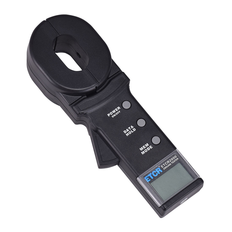
HVTest ETCR2000 User manual

HVTest
HVTest HTFZ-HI User manual

HVTest
HVTest HTRG-H User manual

HVTest
HVTest HT2533 User manual

HVTest
HVTest HTZZ-S10A User manual

HVTest
HVTest HT2671 User manual

HVTest
HVTest HTZZ-5A User manual

HVTest
HVTest HT2670 User manual

HVTest
HVTest HTZZ-1A User manual

HVTest
HVTest HTYX-III User manual

HVTest
HVTest HTJS-M User manual

HVTest
HVTest HTJY-80S User manual

HVTest
HVTest HT2672 User manual

HVTest
HVTest HTYB-3H User manual

HVTest
HVTest TAG-8000 User manual

HVTest
HVTest HTJS-V User manual