Mat –Nr. 669983 / Stand: 09.03.2017 D
9
10 Glossar
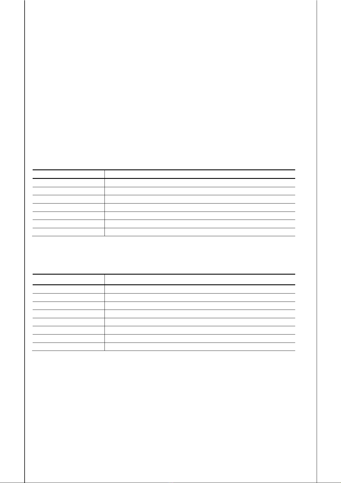
10.1 Begriffe aus der DIN EN ISO 13849
Abkürzung Bedeutung
MTTFDMean time to dangerous failure
Mittlere Zeit bis zum
efahrbrin
enden Ausfall
DCavg Average diagnostic coverage
Durchschnittlicher Diagnose-Deckungsgrad
CCF Common Cause Failure
Fehler gemeinsamer Ursache
PL Performance Level
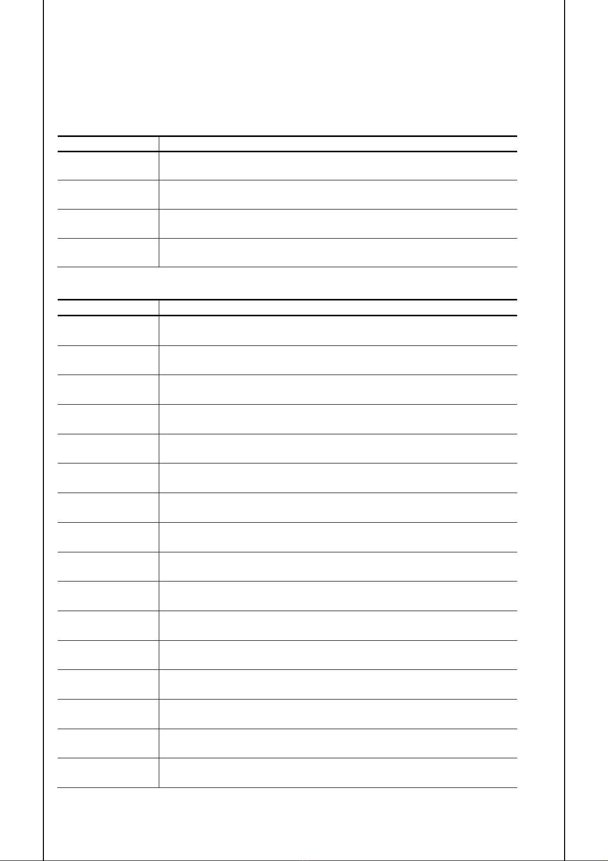
10.2 Begriffe aus der DIN EN 61508
Abkürzung Bedeutung
SIL Safety Integrity Level
Sicherheits-Integritätslevel
HFT Hardware failure tolerance
Hardware Fehler Toleranz
SFF Safe failure fraction
Anteil sicherer Fehler
MooN M out of N architecture
M aus N Architektur
PFH Probability of a Dangerous Failure per Hour
Wahrscheinlichkeit eines gefährlichen Fehlers pro Stunde
FMEDA Failure Mode, Effects and Diagosis Analysis
Fehler Modus, Effekt und Diagnose Analyse
λsd Rate for safe detected failures
Anteil sicherer, erkannter Fehler
λsu Rate for safe undetected failures
Anteil sicherer, nicht erkannter Fehler
λdd Rate for dangerous detected failures
Anteil gefährlicher, erkannter Fehler
λdu Rate for dangerous undetected failures
Anteil gefährlicher, nicht erkannter Fehler
DCsDiagnostic coverage of safe failures
Diagnoseabdeckung für sichere Fehler
DCdDignaostic coverage of dangerous failures
Diagnoseabdeckung für gefährliche Fehler
FIT Failure in time (1 FIT = 1 failure / 10
hours)
Fehler pro Zeiteinheit (1 FIT = 1 Fehler in 109 Stunden)
MTBF Mean time between failure
Mittlere Zeit zwischen dem Auftreten von Fehlern
MTTF Mean time to failure
Mittlere Zeit bis zum Auftreten eines Fehlers
MTTR Mean time to repair
Mittlere Zeit bis zur Reparatur