Hydrolevel Company CycleGard CG470 Series User manual

1/4"
Automatically shuts off burn r, aft r d lay, in a low wat r
condition to pr v nt dry firing.
Enhanc d Int rmitt nt L v l T st t chnology – activ only
wh n wat r is at boiling t mp ratur . Provid s add d prot c-
tion in foaming and volatil wat r conditions.
Tim d lay s qu ncing pr v nts burn r short-cycling caus d
by mom ntary dips in wat r l v l and allows a wat r f d r
to r pl nish wat r to a l v l abov th prob .
Int gral t mp ratur s nsor provid s High Limit Lock-Out
f atur for an unpr c d nt d l v l of boil r prot ction.
The probe may be
installed in the boiler
above the lowest safe
water level established by
the boiler manufacturer.
Most manufacturers pro-
vide a suitable tapping in
the side of the boiler.
STEP 2 Loos n th two control cov r scr ws and r mov th cov r.
Ass mbl th chassis to th prob flang and s cur with th scr ws provid d.
STEP 3 Plug th wir l ad from th prob into th
mating conn ction on th circuit board.
STEP 1 Scr w th prob
into th LWCO tapping in th boil-
r. Allow 1/4" cl aranc from th
prob to any boil r surfac , tub
or baffl . NOTE: Exc ssiv us of
T flon tap to s al prob piping
thr ads may insulat th control
from boil r ground. This could
r sult in th control not op rating.
Low Wate Cut-Offs
Fo Steam Boile s
120 VAC Operating Voltage
Max. Pressure 15 psi
U.S. Patent Nos. 5,739,504 & 6,390,027
CG470 Series
WARNING Electrical shock hazard. To pr v nt l ctrical shock, d ath or
quipm nt damag , disconn ct pow r supply b for
installing or s rvicing control. Only qualifi d p rsonn l may install or s rvic this control in
accordanc with local cod s and ordinanc s. R ad instructions compl t ly b for proc ding.
CAUTIONTo pr v nt s rious
burns, boil r
should b thoroughly cool d b for installing or
s rvicing control.
WARNING Frozen pipes/water da age. C ntral h ating syst ms ar pron to shut down as a r sult of pow r or fu l outag s,
saf ty r lat d fault conditions or quipm nt failur . Installation of fr z prot ction monitoring or oth r pr cautions
is r comm nd d for unatt nd d dw llings in climat s subj ct to sustain b low-fr zing t mp ratur s.
83 Water Street • New Haven, CT 06511 • Phone (203) 776-0473 • FAX (203) 773-1019 • www.hydrolevel.com
1
MOUNTING THE CONTROL
SAFE
WATER
LINE

Conn ct input voltag (120 VAC, 60 HZ) to
t rminals 1 and 2.
Conn ct t rminal 2 to burn r circuit n utral.
Conn ct t rminal P2 to burn r Circuit in
s ri s with oth r limit controls. Consult boil-
r manufactur r instructions for prop r t r-
minal conn ctions. Control should b wir d
in s ri s with and b for oth r limit controls.
Optional water feeder connection.
Conn ct f d r N to t rminal 2. Conn ct F d r
H to t rminal 1. Conn ct f d r “FEED” or “W”
to t rminal A. For wat r f d rs with 2 l ads,
conn ct f d r n utral to t rminal 2 and f d r
hot to t rminal A.
NOTE: Use of a solenoid valve or McDonnell &
Miller Model 1 1A water feeder may cause
flooding and is not recommended for use with
this low water cut-off.
OPTIONAL ACTIVATION
Conn ct “SMTCYC” t rminal on th
Cycl Gard control to th orang burn r wir
(120VAC) locat d und r th primary. S
d tail illustration at th right.
See SmartCycle description on next page.
1 2 3
4
Detail of SmartCycle Connection
Model CG470
2
WIRING – Model CG470

OPERATING TEST PROCEDURE
1. Aft r installation, bring th boil r wat r to
a saf op rating l v l, turn on pow r and
s t th th rmostat to call for h at. Th
amb r LED lamp should b off. T e boiler
will fire immediately.
2. Slowlylow r th boil r wat r to a point
b low th prob . Th amb r LED lamp on
th control will light. Th lamp may b gin
to flick r with th bouncing wat r l v l.
Stop draining th boil r wh n th lamp
glows st adily. NOTE: Th wat r should
not b low r d b yond a visibl point in
th gaug glass.
3. Th boil r will shut down within 15
s conds.
TEST BUTTON
Th CG470 is quipp d with a button to t st
wiring and control op ration. To us th t st
button, r mov th cov r and pr ss th but-
ton locat d on th circuit board. Th burn r
will shut off for th l ngth of tim th button
is pr ss d. If th burn r do s not shut off,
r mov pow r and r ch ck wiring. Not :
Hydrol v l r comm nds low ring th wat r
l v l (as d scrib d in “Op rating T st
Proc dur ”) to functionally t st th control
and prob op ration on an annual basis.
IF BURNER DOES NOT SHUT DOWN IN
LOW WATER
1. Ch ck t rminal block wiring to insur that
all conn ctions ar corr ct.
2. Ch ck th prob installation to insur that
th r is 1/4" cl aranc from any surfac
within th boil r or pip . (R f r to St p 1
on pag 1 of this instruction sh t.
3. Cl an th boil r in accordanc with th
manufactur r’s instructions. Machining
oils, gr as , rust and oth r contaminants
in th boil r wat r can caus foaming or
surging and mak a low wat r condition
difficult to d t ct during burn r op ration.
IF THE AMBER LED LAMP IS ON
Th amb r LED lamp indicat s that th wat r
is b low th prob . If th gaug glass shows
that th wat r is at th corr ct op rating l v l
and th amb r LED is lit, ch ck th following:
1. Ch ck for plugg d gaug glass.
2. Mak sur prob l ad wir is prop rly
s cur d to th t rminal.
3. Ch ck for prop r ground b tw n prob
and boil r sh ll. Exc ssiv us of T flon
tap or s aling compound may isolat th
prob from th boil r sh ll.
4. R mov prob and xamin for oily
r sidu . Cl an prob with st l wool and
skim boil r.
IF THE RED LED LAMP IS ON
Th r d LED lamp indicat s that th boil r
has xp ri nc d an unsaf t mp ratur
(250°F). Th control will lock out th burn r
circuit and illuminat th LED wh n this
occurs. DANGER: Adding wat r to an ov r-
h at d boil r can caus an xplosion. Th
boil r must b allow d to fully cool b for
adding wat r. Th boil r should b valuat d
by a qualifi d s rvic t chnician b for
r storing op ration. Th Cycl Gard control
should b r plac d.
IF THE RED LED LAMP IS BLINKING
A blinking r d LED lamp indicat s that th
control has b n lock d out on an unsaf
t mp ratur at som point in its history. Th
Cycl Gard control should b r plac d.
IF THE GREEN LED LAMP IS ON
Th gr n LED lamp indicat s that th control
is conducting an Int rmitt nt L v l T st. Th
burn r do s not fir during th t st p riod.
S Int rmitt nt L v l T st F atur on this
pag for mor d tails.
Enhanced Intermittent
Level Test Feature
To provid add d prot ction to today’s small-
r boil rs, Cycl Gard Mod l CG470 is
quipp d with an nhanc d Int rmitt nt L v l
T st (ILT) f atur . Fift n minut s aft r th
boil r r ach s boiling t mp ratur , th ILT
f atur r mov s pow r from th burn r for
60 s conds. During this ILT t st, foam dissi-
pat s and th wat r l v l quickly stabiliz s,
allowing th CG470 to monitor th tru wat r
l v l in th boil r. If th wat r in th boil r is
at a saf l v l, th control will r - n rgiz th
burn r. If th wat r l v l has dropp d to a
l v l b low th prob , th control will k p
th burn r off (and s nd pow r to an optional
wat r f d r) until th wat r l v l is r pl n-
ish d. Th 60 s cond ILT t st will r p at
v ry 15 minut s as long as th boil r
r mains at boiling t mp ratur . Th ILT f a-
tur dis ngag s wh n th boil r t mp ratur
is b low th boiling point.
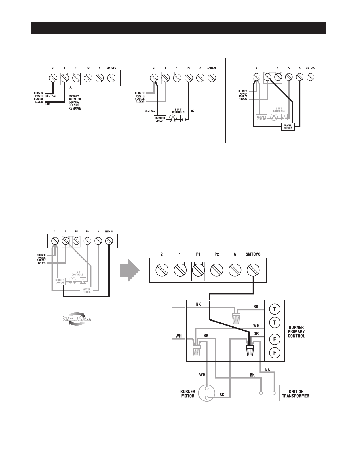
Th optional Smart Cycl f atur is d sign d to
pr v nt unn c ssary ILT t sts in th v nt th
burn r cycl s off for oth r r asons ( x. pr s-
sur limit or th rmostat calls). Wh n activat d
(s wiring on pr vious pag ), th Smart Cycl
f atur r starts th 15 minut timing s qu nc
ach tim th burn r fir s. So, for xampl , if
th pr ssur control shuts down th burn r,
th Smart Cycl f atur will r s t th 15
minut clock onc th pr ssur control r -
n rgiz s th burn r. This pr v nts an ILT
from occurring soon r than is n d d as th
control was abl to monitor th s ttl d wat r
l v l during th pr ssur limit int rruption.
Hi Temp Lock-Out
Unlik any oth r st am low wat r cut-off, th
CG470 monitors boil r t mp ratur in addi-
tion to wat r l v l. This f atur will shut
down and lock out th burn r circuit if th
boil r r ach s an unsaf l v l (250°F).
3
OPERATING INSTRUCTIONS
NOTE: For prop r low wat r cut-off op ration, th boil r should b cl an d at initial installation and p riodically th r aft r. R f r to th boil r
manufactur r’s instructions for cl aning proc dur s.

The Pro e Makes the Difference Th prob us d in all Hydrol v l controls off rs you distinctiv advantag s. Unlik float
d vic s, th r ar no moving parts to w ar stick, or “hang-up” th in harsh boil r nvironm nt. A stuck or “hung-up” float can caus dang rous
low wat r conditions. And if sudd nly r l as d, a float can f d cold wat r into ov rh at d tub s or plat s and caus xplosiv r sults. Th
Hydrol v l control has no float bowl so s dim nt cannot coll ct. Th r liabl microproc ssor-bas d d sign and low maint nanc prob ar
d sign d to provid y ars of troubl fr op ration.
EL1230 – STANDARD MODEL – 3/4" NPT EL1232-P – 3/4" NPT
4CG470-1012
MAINTENANCE
PROBES
DIMENSIONS SPECIFICATIONS
To nsur optimum p rformanc r mov and insp ct prob annually. Cl an any s dim nt or scal from th prob using a scouring pad or st l
wool. R -install th prob and p rform th Op rating T st Proc dur d scrib d on pag 3.
83 Water Street • New Haven, CT 06511 • Phone (203) 776-0473 • FAX (203) 773-1019 • www.hydrolevel.com
LIMITED MANUFACTURERʼS WARRANTY
W warrant products manufactur d by Hydrol v l Company to b fr from d f cts in
mat rial and workmanship for a p riod of two y ars from th dat of manufactur or
on y ar from th dat of installation, which v r occurs first. In th v nt of any claim
und r this warranty or oth rwis with r sp ct to our products which is mad within
such p riod, w will, at our option, r pair or r plac such products or r fund th pur-
chas pric paid to us by you for such products. In no v nt shall Hydrol v l
Company b liabl for any oth r loss or damag , wh th r dir ct, indir ct, incid ntal or
cons qu ntial. This warranty is your EXCLUSIVE r m dy and shall b IN PLACE OF
any oth r warranty or guarant , xpr ss or impli d, including, without limitation, any
warranty of MERCHANTABILITY or fitn ss for a particular purpos . This warranty
may not b assign d or transf rr d and any unauthoriz d transf r or assignm nt
th r of shall b void and of no forc or ff ct.
MAXIMUM PRESSURE: 15 PSI
INPUT VOLTAGE: 120 VAC, 60 HZ
SWITCH RATINGS: 5.8 FLA, 34.8 LRA
SWITCH CONTACTS: SPDT
ALARM CIRCUIT: 125 VA @ 120 VAC
Pilot Duty
Other Hydrolevel Company Boiler Supplies manuals