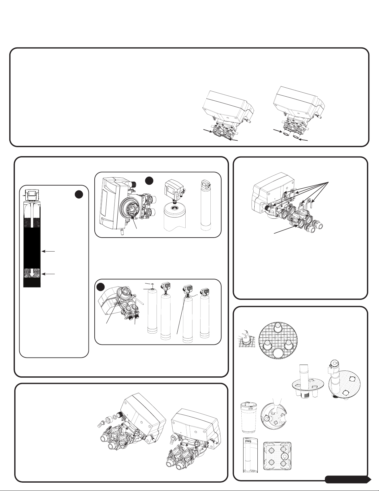
manuals.online logo
Brands
  1. Home
  2. •
  3. Brands
  4. •
  5. Hydrotech
  6. •
  7. Water Dispenser
  8. •
  9. Hydrotech 89HE Instruction manual

Hydrotech 89HE Instruction manual

Inlet Outlet
Outlet Inlet
Upflow Valve Downflow Valve
Resin
Support Bed
Gravel
O-ring
1. Media Installation
CAUTION: Make sure the power cord of the valve
doesnt get caught between the threads
Grease port Orings using brush
(not included) or your finger
(Make sure to wear protective
gloves)
Attach
Upper
Basket
1
2
3
Clips
Bypass
Unscrew Spill Cap
D-Tube
89 Softener Quick Start Manual
STEP 1 –INSTALLATION STEPS
Determine the best location for your water Softener, bearing in mind the location of your water supply lines, drain line and 120 volt AC electrical outlet. Subjecting the Softener to freezing or
temperatures above 43°C (110°F) will void the warranty.
Please notice the inlet and outlet labels on the valve as shown here to determine
the position of the equipment:
For UF Softener - The inlet should be on the right hand side of the valve and out
on the left hand side
For DF Softener - The inlet should be on the left hand side of the valve and out
on the right hand side
STEP 2 –PREPARATIONS
1. Fill tank one quarter full of
water to protect distribution
during gravel installation.
Place the media into the
tank in the order indicated
above. Slowly and carefully
add the gravel support bed
and the ltration media
leveling each layer as it is
placed into the tank.
2. Unplug the riser tube, carefully position the valve over it and turn the
valve into the threads in the berglass tank, tightening securely into
tank. Note: Ensure that the internal O-ring in the valve ts securely
over the riser tube. Silicone grease (part # 92360) or other food grade
lubricant may be applied to the O-ring to ease installation of the riser
tube.
3. Lube the bottomValve Orings with the grease supplied, Attach the
Upper Basket. Unscrew the spill cap. Carefully Slide the D-Tube inside
the Valve and Screw theValve inside the Tank such that the power
cord doesnt get caught between the valve and the tank.
STEP 3 –ATTACHING BYPASS TO VALVE
Make sure the bypass is attached well to the control valve. Connect the
elbow connectors to the bypass with red clips. Connect the inlet and
outlet of the water Softener to the plumbing of the house. The control
valve must not be submitted to temperatures above 43°C (110°F). When
sweat ttings are used, to avoid damaging the control valve, solder the
threaded copper adapters to the copper pipe and then, using Teon
tape, screw the assembly into the bypass valve.
Do not use pipe thread compound as it may attack the material in the
valve body.
STEP 4 –DRAIN LINE CONNECTION
UsingTeon tape,screw the 1/2”hose barb
and attach oring into the drain port in the
valve. Attach 1/2”drain hose (Supplied with
some models and brands) to the hose barb
and tighten securely with a hose clamp
(Supplied with some models and brands).
Run the drain line to a oor drain or a
laundry drain. Complete any necessary
plumbing.
STEP 5 –ASSEMBLING BRINE TANK
a) Attach the three brine grid
legs to grid plate. The legs will
snap on to the tabs of the salt
plate making a“click”sound.
For square brine tank there are
four legs.)
c) Drop the brine grid with brine well
inside the brine tank such that the
nut tting faces the hole on the brine
tank. Then press the grid evenly inside
the brine tank until the brine grid legs
touches the bottom of the brine tank.
b) Insert the brine well
assembly inside the grid
plate
IMPORTANT: IN ROUND BRINE TANK, IT IS
IMPORTANT TO ALIGN THE HANDLE TO THE BRINE
WELL AS SHOWN
The hole in the brine tank should line up with
the brine line as shown for round and square
brine tank.
CONTINUED ON NEXT PAGE
Insert Sleeve inside the Tubing
The new versions of 89 Valve have Quick
Connect Brine Fitting
STEP 6. ATTACHING BRINE TUBING TO
THE BRINE LINE OF THE VALVE
Insert Sleeve
Optional
Overow
Assembly
Brine Valve
Connector Detail
AC120V/10A
Current Protect Socket Brine Elbow
Assembly
Water Pipe Outlet
Main tank
5/8”Drain Line
Bypass assembly
5/8”Overow Line
Floor drain
Optional
Pipes Fixed
Structure
Drain Elbow
Assembly
Outlet
Brine Tank
3/8” Brine Tube
Inlet
Water Pipe Inlet
Cold (Raw water)
Cold (Filtered water) Cold (R
aw water)
Check Valve
Water Heater
Hot (Soft Water)
Upow Water Softener
Filter
InIn OutInOut
Out
Cold (Soft Water)
T
o Outside Faucet
Upflow Water Softener Installation Downflow Water Softener Installation
NOTICE - THERE ARE INLET
AND OUTLET LABELS
ON THE VALVE. PLEASE
MAKE SURE TO PLUMB AS
SHOWN HERE
Outlet
Inlet
NOTICE - THERE ARE INLET
AND OUTLET LABELS
ON THE VALVE. PLEASE
MAKE SURE TO PLUMB AS
SHOWN HERE
Inlet
Outlet
Overow
Assembly
Brine Valve
Connector Detail
AC120V/10A
Current Protect Socket Brine Elbow
Assembly
Water Pipe Inlet
Main tank
5/8” Drain Line
Bypass assembly
5/8” Overow Line
Floor drain
Optional
Pipes Fixed
Structure
Drain Elbow
Assembly
Inlet
Brine Tank
3/8” Brine Tube
Outlet
Water Pipe Outlet
Cold (Raw water)
Cold (Filtered water) Cold (Raw water)
Check Valve
Water Heater
Hot (Soft Water)
Downow Water Softener
Filter
In In Out
Out
Cold (Soft Water)
T
o Outside Faucet
OutIn
STEP 5 –ASSEMBLING BRINE TANK CONTINUED
STEP 7 –CONNECT SOFTENER TO THE HOUSE PLUMBING
d) Take the brine tube and insert the nut and plastic sleeve
as shown below.
e) Insert the tube in the oat assembly elbow and hand tighten the nut. In
many cases the brine line already come installed from the factory. Leave the
other end of the brine line tube inside the brine tank
f)For installation of brine tank at the installation site, pull the other end of
the brine tube from the hole on the brine tank. The completed assembly
is shown on right.
Any solder joints near the valve must be done before connecting any piping to the valve. Always leave at least 6”(152 mm) between the valve and joints when soldering pipes that are connected to
the valve. Failure to do this could cause damage to the valve.
Sample
Connection
Sample
Connection
SERVICE
BYPASS
Sample
Connection
Sample
Connection
SERVICE
BYPASS
Date and Time
Hardness
Manual Regen.
Dealer Information
Main Menu
Regen. Now?
Regen. Tonight?
Press To Cancel
Press To Conrm
Backwashing ...
Any Key 3sTo Next
13:59
18%
Brine Draw ...
Any Key 3sTo Next
18%
Rinse ...
Any Key 3sTo Next
18%
Brine Rell ...
Any Key 3sTo Next
18%
3”
Date and Time
Hardness
Manual Regen.
Dealer Information
Main Menu
= = Date and Time = =
17-Feb-2016 12:25pm
Press To Cancel
Press To Conrm
Setting Complete
Press To Return
Auto On
Date and Time
Hardness
Manual Regen.
Dealer Information
Main Menu
= Main Menu =
Regen. Time Setting
System Capacity
Salt Mode Setting
Advanced Menu
= = Regen. Time = =
02:25AM
Press To Cancel
Press To Conrm
Setting Complete
Press To Return
Date and Time
Hardness
Manual Regen.
Dealer Information
Main Menu
QUALITY WATER
666 3 AVE
CHIGAGO IL
TEL 12345678
Setting Complete
Press To Return
Date and Time
Hardness
Manual Regen.
Dealer Information
Main Menu
=Hardness =
25 GPG
Press To Cancel
Press To Conrm
Setting Complete
Press To Return
Dealer
information
input letter
by letter
Set up Regeneration Time:
Press Set
Key till
you hear
“Beep”
Set up Current Time of the Day
and hardness:
STEP 8 –START UP INSTRUCTIONS
1.Connect the transformer to the
valve. Plug the 12-volt transformer
into a 120VAC 60 Hz outlet.
2.Open the brine tank/cabinet salt lid and
add water until there is approximately
3”(75 mm) of water in the tank. Do not
add salt to the brine tank at this time.
3.When power is supplied to the control,
the screen will display“INITIALIZING
WAIT PLEASE”while it nds the service
position.
5.Please set up date and time of day and hardness.The Valve is already programmed from factory for Softener Models.
4.Manually regenerate the valve. If screen is locked, press Menu Key
for 5 seconds to unlock.
6.Add Salt to the brine tank/cabinet
Put 40 kgs of crystal water softener salt in
the brine tank. The unit will automatically
ll the water to the correct level when it
regenerates.
MENU
SET
MENU
SET
MENU
SET
MENU
SET
This function is to accept the values if changed and advance to the next page in the menu.
These buttons are used to increase or decrease the value of the settings while in the
programming mode.
This function is to enter the basic set up information required at the time of installation.
Key Pad Configuration:
Manual Regeneration
Manually Regenerate theValve and move it to backwash position. Press Menu Key
and Scroll down using Up and Down Arrow buttons to“Manual Regen”.
Press“SET” Select“Regen Now”
Set Up Current Time of Day and Regeneration Time
When Softener Should Regenerate When No one
uses Water in House.
Press Menu Key and Select“Date andTime”using “Set” button
and set For setting the regeneration time, Press Menu Key and Select
Main Menu till you hear a beep and select Regen time
Familiarize with Button Configuration:
MENU
SET
Date and Time
18-Apr-2016 10:35AM
Gal Remain 1400
Flow Rate 3 gpm/min
MENU
SET
System initializing
Please wait
The controller will show the following on the
screen - Time, Date and Gallons Remaining for
Regeneration
TOLL-FREE: 1-877-288-9888
Regina, SK • Cambridge, ON • Whitestown, IN
Phoenix, AZ • Houston, TX • Guadalajara, MX55244 2023-10-18
Follow the Instruction Manual to Complete
the Installation of the Product

This manual suits for next models

1

Other Hydrotech Water Dispenser manuals

Hydrotech 89UF Series User manual

Hydrotech

Hydrotech 89UF Series User manual

Hydrotech 785 DF User manual

Hydrotech

Hydrotech 785 DF User manual

Hydrotech 89DF Series User manual

Hydrotech

Hydrotech 89DF Series User manual

Hydrotech 6700XTR Series User manual

Hydrotech

Hydrotech 6700XTR Series User manual

Hydrotech NRV TO-150 User manual

Hydrotech

Hydrotech NRV TO-150 User manual

Hydrotech 89 Instruction manual

Hydrotech

Hydrotech 89 Instruction manual

Hydrotech 89 Valve User manual

Hydrotech

Hydrotech 89 Valve User manual

Hydrotech 785UF Specification sheet

Hydrotech

Hydrotech 785UF Specification sheet

Hydrotech 89DF HIM User manual

Hydrotech

Hydrotech 89DF HIM User manual

Hydrotech 785 MBTO User manual

Hydrotech

Hydrotech 785 MBTO User manual

Hydrotech 785 Series Specification sheet

Hydrotech

Hydrotech 785 Series Specification sheet

Hydrotech 765 Specification sheet

Hydrotech

Hydrotech 765 Specification sheet

Hydrotech 785HE Specification sheet

Hydrotech

Hydrotech 785HE Specification sheet

Hydrotech 565 Specification sheet

Hydrotech

Hydrotech 565 Specification sheet

Hydrotech 7000 SXT Valve User manual

Hydrotech

Hydrotech 7000 SXT Valve User manual

Hydrotech 5600 Calendar Clock Valve User manual

Hydrotech

Hydrotech 5600 Calendar Clock Valve User manual

Hydrotech 565BM-75 User manual

Hydrotech

Hydrotech 565BM-75 User manual

Hydrotech 89 HIMTLC Series User manual

Hydrotech

Hydrotech 89 HIMTLC Series User manual

Popular Water Dispenser manuals by other brands

Soleus Air Aqua Sub WA2-02-50 instruction manual

Soleus Air

Soleus Air Aqua Sub WA2-02-50 instruction manual

Elkay EWA14 3GJO Series Installation, care & use manual

Elkay

Elkay EWA14 3GJO Series Installation, care & use manual

InSinkErator HOT100 Installation and replacement instructions

InSinkErator

InSinkErator HOT100 Installation and replacement instructions

CASO DESIGN HW 500 Touch Original operating manual

CASO DESIGN

CASO DESIGN HW 500 Touch Original operating manual

Watts OneFlow OF120-2 Installation, operation and maintenance manual

Watts

Watts OneFlow OF120-2 Installation, operation and maintenance manual

Animo WKT 3 HA manual

Animo

Animo WKT 3 HA manual

APURO K711-A instruction manual

APURO

APURO K711-A instruction manual

Crystal Mountain Everest POU Series Service manual

Crystal Mountain

Crystal Mountain Everest POU Series Service manual

Ispring UVF11A Installation and maintenance manual

Ispring

Ispring UVF11A Installation and maintenance manual

Viva 7LIECH-SC-SSF user manual

Viva

Viva 7LIECH-SC-SSF user manual

Follett 25FB425A Operation and service manual

Follett

Follett 25FB425A Operation and service manual

Bunn ThermoFresh SERVER Use & care instructions

Bunn

Bunn ThermoFresh SERVER Use & care instructions

KitchenAid INSTANT-HOT KHWC160 Installation instructions and use and care manual

KitchenAid

KitchenAid INSTANT-HOT KHWC160 Installation instructions and use and care manual

Kenmore Elite INTELLISOFT 420 SERIES 625.38426 owner's manual

Kenmore

Kenmore Elite INTELLISOFT 420 SERIES 625.38426 owner's manual

Bradley S19-210DC Installation

Bradley

Bradley S19-210DC Installation

Culligan Aqua-Cleer CC Basic Installation & operation manual

Culligan

Culligan Aqua-Cleer CC Basic Installation & operation manual

Kenmore 7146611 installation manual

Kenmore

Kenmore 7146611 installation manual

GE GNCF04H/GXCF05D owner's manual

GE

GE GNCF04H/GXCF05D owner's manual

manuals.online logo
manuals.online logoBrands
  • About & Mission
  • Contact us
  • Privacy Policy
  • Terms and Conditions

Copyright 2025 Manuals.Online. All Rights Reserved.