6 7
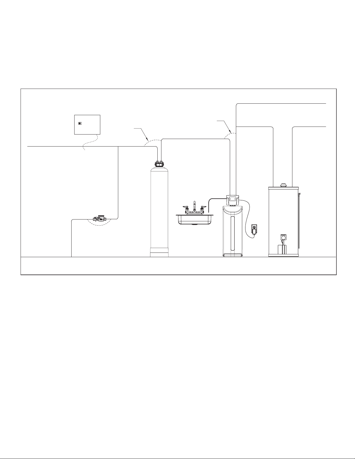
OUTLET
INLET
8QILOWHUHG:DWHU%\SDVV
/RRS&XW&DSSHG
*URXQG6WUDS5HTXLUHG%HFDXVH
RI%UHDNLQ&RQWLQXLW\
)LOWHUHG:DWHU/LQHLQ+RPH
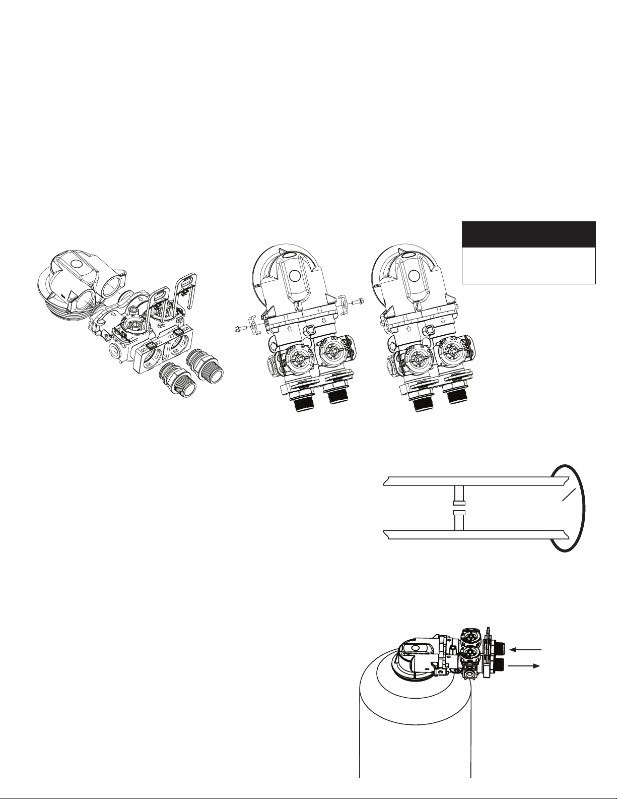
NOTE
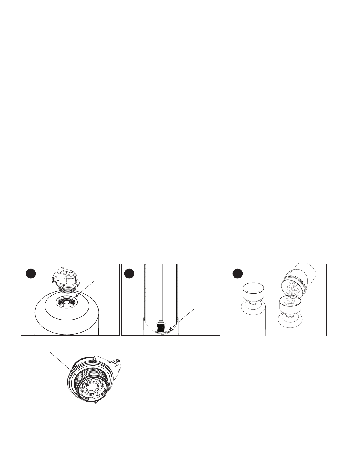
Be sure to use silicone
grease on the O-rings
(Provided)
s Place the filter tank as close as possible to the pressure tank (well
system) or water meter (city water).
s Connect the filter to the main water supply pipe BEFORE the water
heater. DO NOT RUN HOT WATER THROUGH THE FILTER.
Temperature of water passing through the filter must be less than
100 deg. F
s Do not install the filter in a place where it could freeze. Damage
caused by freezing is not covered by the warranty.
s Put the filter in a place where water damage is least likely to occur
if a leak develops. The manufacturer will not repair or pay for water
damage.
s If installing in an outside location, you must take the steps
necessary to assure the filter, installation plumbing, wiring, etc.,
are as well protected from the elements, contamination,
vandalism, etc., as when installed indoors.
s Keep the filter out of direct sunlight. The sun’s heat may
soften and distort plastic parts.
Where To Install The Filter
INSTALLATION INSTRUCTIONS
1.If your hot water tank is electric, turn off the power to it to avoid damage to the element in the tank.
2.If you have a private well, turn the power off to the pump and then shut off the main
water shut off valve. If you have municipal water, simply shut off the main valve. Go
to the faucet, (preferably on the lowest floor of the house) turn on the cold water until
all pressure is relieved and the flow of water stops.
3.Connect the inlet and outlet of the filter using appropriate fittings.
Perform all plumbing according to local plumbing codes.
•ON COPPER PLUMBING SYSTEMS BE SURE TO INSTALL A GROUNDING WIRE
BETWEEN THE INLET AND OUTLET PIPING TO MAINTAIN GROUNDING.
The Inlet and Outlet should be as per below illustration. this will ensure that
water will flow through the filter under upflow configuration
Any solder joints near the valve must be done before connecting any piping to
the valve. Always leave at least 6”(152 mm) between the valve and joints
when soldering pipes that are connected to the valve. Failure to do this could
cause damage to the valve.
4.Using the Allen Key (included), place the unit in the bypass position. Slowly
turn on the main water supply. At the nearest cold treated water tap nearby
remove the faucet screen, open the faucet and let water run a few minutes or
until the system is free of any air or foreign material resulting from the
plumbing work.
INSTALL BYPASS TO THE FILTER
The Inlet and Outlet should be as per below
illustration. This will ensure that water will
flow through the filter in an upflow
configuration