manuals.online logo
Brands
  1. Home
  2. •
  3. Brands
  4. •
  5. Hytronik
  6. •
  7. Accessories
  8. •
  9. Hytronik HMW34 Quick guide

Hytronik HMW34 Quick guide

1. Technical Specifications
Product type High bay microwave DALI sensor (Daylight harvest)
Operating voltage 220~240VAC 50/60Hz
Switched power Maximum 20pcs DALI devices Maximum 40mA
Power consumption < 0.5W
Detection angle 360o
Detection area (Max.)*
Detection range 10% / 50% / 75% / 100%
Hold time 2s / 30s / 1min / 5min / 10min / 15min / 20min / 30min
Stand-by time 0s / 10s / 1min / 5min / 10min / 30min / 1h / +
Stand-by dimming level 10% / 20% / 30% / 50%
Daylight threshold 50 ~ 500Lux , Disable
Warmming-up time 20s
Operating temperature -20oC ~ +50oC
IP rating IP65
3. Rotary Switch Settings
Detection
range
Channel
0
1
2
3
4
5
6
7
8
9
A
B
C
D
E
F
100%
100%
100%
100%
100%
100%
100%
100%
100%
100%
100%
100%
100%
100%
100%
100%
5s
1min
5min
5min
5min
5min
10min
10min
10min
10min
20min
20min
30min
30min
30min
5s
10s
5min
10min
+∞
+∞
+∞
30min
+∞
+∞
+∞
1h
+∞
+∞
+∞
+∞
10s
10%
10%
10%
10%
10%
30%
10%
10%
10%
30%
10%
30%
10%
30%
50%
10%
Disable
50Lux
50Lux
75Lux
100Lux
200Lux
50Lux
75Lux
100Lux
200Lux
100Lux
200Lux
100Lux
200Lux
400Lux
100Lux
Hold
time
Stand-by
time
Stand-by
dimming level
Daylight
threshold
A rotary switch is built inside the sensor for
scene selection / fast programming. Total
16 channels available:
Note: settings can also be changed by remote control HRC-11. The last action controls.
8
HIGH BAY MICROWAVE DALI SENSOR HMW34
Installation and Instruction Manual
Rotary switch preset (Please
see the location in 2. Installation)
The built-in daylight sensor can read ambient natural light and switch off the fixture automatically
whenever artificial light is not required (natural light lux level exceeds daylight threshold).
Note: if the stand-by time is preset at "+∞", the fixture never switches off even when natural light
is sufficient.
4.2 Lux Off Function
4. Functions
Daylight sensor measures the available natural light of the surrounding, calculates how much electrical
light is needed to reach the total lux expected. The demand is given to the LED driver by DALI signal, so as
to deliver the needed amount of electric light.
4.1 Daylight Harvest (Daylight Regulating)
0 24
Light level
Time (hrs)
Normal Electric Light
Daylight controlled light
Energy Saving Zone
Natural light
Hold time
Stand-by time
HMW34-20181126-A1
2. Installation
Warnings:
1. Installation of the sensor involves connecting it to the mains supply. This work must be
carried out by a specialist in accordance with electrotechnical regulations.
2. Disconnect power supply before installing.
The light will flash ONCE rapidly after receiving the command from the remote controller.
Note: There is no load indication (the light will not flash) when button ON/OFF, POWER 100%
or POWER 80% is pressed.
4.3 Load Indication
A. Ceiling mount
B. Screw to the Luminaire by conduit
C. Attach to the shade by clamp
91.5
59.3
57.3
47.5
4.1
80.7
75
4.1
66.6
81.5
59.6
66.6
89.9
0.825”
75
64
59.3
57.3
35.2
47.5
84.5
59.3
ぶ
29
163.2
66.6
75
33.7
15
28.5
4.5
ぶ
4.5
59.6
Sensor module
Photocell
LED indicator
Infrared receiver
Rotary switch
Cable entry
Installation rack
Photocell
Sensor module
LED indicator
Infrared receiver
Rotary switch
Cable entry
Sensor module
Photocell
LED indicator Infrared receiver
Rotary switch
Angle adjustment
Luminaire clamp
Note:We recommend the mounting distance between sensor to sensor
should be more than 2m to prevent sensors from false-triggering.
Installation Height : 20m (forklift) 15m (person)
Detection Range (Ø) :20m
24.5
8. Troubleshooting
Descriptions of the
Button Functions
(remote control HRC-11)
MALFUNCTION CAUSE REMEDY CAUSE REMEDY
The fixture does not light up
The fixture is always on
Check detection area setting
The fixture is on when it should not
Incorrect daylight threshold setting
Continous movement in the detection zone
Sudden change in temperature due to weather (wind, rain, snow) or air
expelled from fans, open windows
Detection zone not targeted
Faulty fixture
No power supply
Adjust daylight threshold setting
Replace fixture
Check power to sensor
Check detection area setting
Adjust zone, change installation site
7.
Dual tech & RF mode [ zone ]
All buttons in zone are disabled.
14
14
Detection range [ zone ]
Press buttons in zone to set detection range at 100% / 75% /
50% / 10%.
8
8
RESET[ button ]
Press button , all settings go back to the rotary switch settings.
2
2
Shift [ button ]
Press button , the LED on the top left corner is on for indication.
All values / settings in RED are valid for 20 seconds.
3
3
Auto Mode [ button ]
Press button to initiate automatic mode.The sensor starts working
and all settings remain as before the light was switched ON/OFF.
Note: the function of Semi-auto is disabled.
4
4
Scene prog. [ zone ] (One-key-commissioning)
1. Press button “Start” to program.
2. Select the buttons in “Detection range”, / “Daylight threshold”,
“Hold time”, “Stand-by time”, “Stand-by dimming level” to
set all parameters.
3. Press button “Memory” to save all the settings programmed in the
remote control.
4. Press button “Apply” to set the settings to each sensor unit(s).
For example, to pre-set detection range 100%, daylight threshold
Disable, hold time 5min, stand-by time +∞, stand-by dimming level
30%, the steps should be as follows:
Press button Start, button 100%, Disable, Shift, 5min,
Shift, +∞, 30%, Memory. By pointing to the sensor unit(s)
and pressing Apply, all settings are passed on the sensor(s).
7
7
7
7
3
3
8
8 9
10
10 11
1312
11 12 13
Brightness +/- [ button ]
Press button to adjust the light brightness to reset the target lux level.
6
6
Power output [ button ]
Press button , the light output shifts between 80% and 100%.
Note: the function of “Sensor off” and “Twilight” are disabled.
5
5
Permanent ON/OFF [ ]
Press button ,to select permanent ON or permanent OFF mode.
* Press button / to resume automatic operation.
The mode will change to AUTO Mode after power failure.
button
1
1
2 4
Stand-by dimming level [ zone ]
Press buttons in zone to set the stand-by dimming level at 10% /
20% / 30% / 50%.
13
13
Stand-by time [ zone ]
Press buttons in zone to set the stand-by period at 0s / 10s /
1min / 5min / 10min / 30min / 1h / +∞.
Note: “0s” means on/off control; “+∞” means bi-level control, 100%
on when motion detected, and remains at the stand-by dimming
level when no presence is detected after hold-time.
12
12
Ambient daylight threshold [ button ]
1. Press button Shift, the red LED is on for indication.
2. Press button , the ambient lux level is sampled and set as
daylight threshold / target Lux level.
3
10
10
Daylight threshold [ zone ]
Press buttons in zone to set the daylight sensor at 50Lux / 100Lux
/ 300Lux / 500Lux or Disable as threshold / target Lux level.
Note: 2Lux / 10Lux are disabled.
To set daylight sensor at 100Lux / 300 Lux / 500Lux, press
button Shift at first.
9
9
3
Hold time [ zone ]
Press buttons in zone to set the hold time at 2s / 30s / 1min /
5min / 10min / 15min / 20min / 30min.
Note: 1.To set hold-time at 30s / 5min / 15min / 30min, press button
Shift at first.
2. 2s is for testing purpose only, stand-by period and daylight
sensor settings are disabled in this mode.
* To exit from Test mode, press button or any button in zone .
3
11
11
11
2
HMW34-20181126-A1
5. Wiring Diagram
L
N
DALI
+
DALI
-
L
N
Brown
LED
Driver
Blue
Red
Black
HMW34
Hytronik Industrial Ltd. | www.hytronik.com
3rd Floor, block C, complex building, 155#, Bai'gang road south,
Bai'gang village, Xiao Jin Kou town, Huicheng district, Huizhou 516023
Tel: 86-752-2772020 Fax: 86-752-2777877
HRC-11
&
A
4 hh
4h
1
3
7
9
6
8
10
11
12
13
14
2
4
5
Daylight harvest auto-configuration function
1. Press button “Shift”, the red LED is on for indication.
2. Select a time period and the sensor will do light level measurement
and determine/save the lowest light level (commission line) with
100% light on, so as to set the target lux level automatically.
Note: 1. Make sure the light level measurement covers the night time.
2. The fixture will go into sensor mode after the measurement,
all sensor settings remain unchanged.
10%
30%
75%
50%
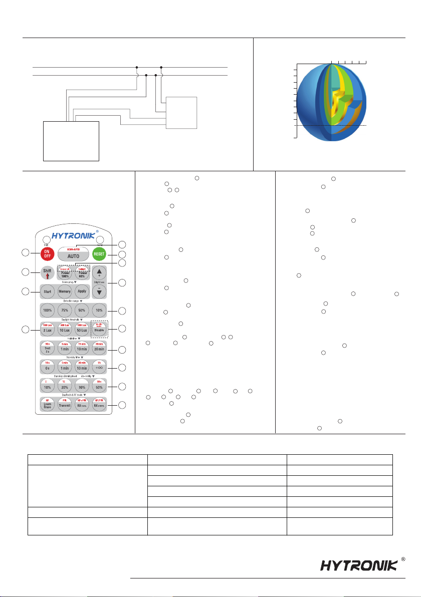
Ceiling mounted detection pattern (m)
Ceiling mounted height(m)
10
0
20
Detection Pattern6.
* For single person walking across, the detection range is reduced by 1/3.
(forklift)

Other Hytronik Accessories manuals

Hytronik HC005S/BT Quick guide

Hytronik

Hytronik HC005S/BT Quick guide

Hytronik DS05 User manual

Hytronik

Hytronik DS05 User manual

Hytronik HMW31 Quick guide

Hytronik

Hytronik HMW31 Quick guide

Hytronik HMW32 User manual

Hytronik

Hytronik HMW32 User manual

Hytronik HIM32 Quick guide

Hytronik

Hytronik HIM32 Quick guide

Hytronik HIR28 Quick guide

Hytronik

Hytronik HIR28 Quick guide

Hytronik HMW20 Quick guide

Hytronik

Hytronik HMW20 Quick guide

Hytronik HIM39/RF Quick guide

Hytronik

Hytronik HIM39/RF Quick guide

Hytronik DS05 Quick guide

Hytronik

Hytronik DS05 Quick guide

Hytronik HIR32 Quick guide

Hytronik

Hytronik HIR32 Quick guide

Hytronik HBIR30/CA Quick guide

Hytronik

Hytronik HBIR30/CA Quick guide

Hytronik HIR27 Quick guide

Hytronik

Hytronik HIR27 Quick guide

Hytronik HMW12 Quick guide

Hytronik

Hytronik HMW12 Quick guide

Hytronik HEC9025/I Quick guide

Hytronik

Hytronik HEC9025/I Quick guide

Hytronik HIM38/RF User manual

Hytronik

Hytronik HIM38/RF User manual

Hytronik HCD418/DH User manual

Hytronik

Hytronik HCD418/DH User manual

Hytronik HCD418 User manual

Hytronik

Hytronik HCD418 User manual

Hytronik HC005S/IR Quick guide

Hytronik

Hytronik HC005S/IR Quick guide

Hytronik HC419VRC/R User manual

Hytronik

Hytronik HC419VRC/R User manual

Hytronik HEC7028 User manual

Hytronik

Hytronik HEC7028 User manual

Hytronik HC428V/RF User manual

Hytronik

Hytronik HC428V/RF User manual

Hytronik Dual Sense HIM11 User manual

Hytronik

Hytronik Dual Sense HIM11 User manual

Hytronik HC005S/BT Quick guide

Hytronik

Hytronik HC005S/BT Quick guide

Hytronik HIM34 User manual

Hytronik

Hytronik HIM34 User manual

Popular Accessories manuals by other brands

FlexiForce LiftMaster 773E manual

FlexiForce

FlexiForce LiftMaster 773E manual

NOVAK REACTOR REVERSIBLE operating instructions

NOVAK

NOVAK REACTOR REVERSIBLE operating instructions

Alpha Alpha CombiMax Installation and servicing instructions

Alpha

Alpha Alpha CombiMax Installation and servicing instructions

Heitronic 500662 Installation and operating instructions

Heitronic

Heitronic 500662 Installation and operating instructions

inventum HNL4111L instruction manual

inventum

inventum HNL4111L instruction manual

Philips HF3507 quick start guide

Philips

Philips HF3507 quick start guide

SICK MPS-M operating instructions

SICK

SICK MPS-M operating instructions

MidNite Solar Whizbang Jr Installation instructions manual

MidNite Solar

MidNite Solar Whizbang Jr Installation instructions manual

DOMUS LINE IR 2.0 12-24Vdc installation manual

DOMUS LINE

DOMUS LINE IR 2.0 12-24Vdc installation manual

Milwaukee M12 AXIS 334 Series Operator's manual

Milwaukee

Milwaukee M12 AXIS 334 Series Operator's manual

netvox R718J user manual

netvox

netvox R718J user manual

Gallet CCH 81 instruction manual

Gallet

Gallet CCH 81 instruction manual

KITMA FCB23F instruction manual

KITMA

KITMA FCB23F instruction manual

ekwb EK-Vector RTX Aorus 2080 installation manual

ekwb

ekwb EK-Vector RTX Aorus 2080 installation manual

MAMAC SYSTEMS TE-701 Series technical information

MAMAC SYSTEMS

MAMAC SYSTEMS TE-701 Series technical information

Endress+Hauser Deltapilot S DB50 technical information

Endress+Hauser

Endress+Hauser Deltapilot S DB50 technical information

UGT UMP-2 operating manual

UGT

UGT UMP-2 operating manual

B&C Speakers Hf Compression Drivers DE 25 Specification sheet

B&C Speakers

B&C Speakers Hf Compression Drivers DE 25 Specification sheet

manuals.online logo
manuals.online logoBrands
  • About & Mission
  • Contact us
  • Privacy Policy
  • Terms and Conditions

Copyright 2025 Manuals.Online. All Rights Reserved.