manuals.online logo
Brands
  1. Home
  2. •
  3. Brands
  4. •
  5. Hytronik
  6. •
  7. Accessories
  8. •
  9. Hytronik HIM39/RF Quick guide

Hytronik HIM39/RF Quick guide

1. Technical Specifications
Product type RF wireless dual sense independent DALI sensor (tri-level control)
Operating voltage 220-240VAC 50/60Hz
Rated load Maximum 20pcs DALI devices, Maximum 40mA
Power consumption < 1.5W
Detection angle 360o
Detection area (Max.)*
Detection range 10% / 50% / 75% / 100%
Hold time 2s / 30s / 1min / 5min / 10min / 15min / 20min / 30min
Stand-by time 0s / 10s / 1min / 5min / 10min / 30min / 1h / +∞
Stand-by dimming level 10% / 20% / 30% / 50%
Daylight threshold 2 ~ 500Lux, Disable
RF transmission distance 30 meters in the open area
RF frequency 868MHz (FSK mode)
Warming up time 30s
Operating temperature -20oC ~ +50oC
IP rating IP65
Sensor mode HF, PIR, HF+PIR, HF / PIR
3. Rotary Switch for RF grouping
4. Functions
The built-in daylight sensor can read ambient natural light and switch off the fixture automatically
whenever artificial light is not required (natural light lux level exceeds daylight threshold).
Note: if the stand-by time is preset at "+∞", the fixture never switches off even when natural light
is sufficient.
4.2 Lux Off Function
Hytronik builds this function inside the motion sensor to achieve tri-level control, for some areas it requires
a light change notice before switch-off.
It offers 3 levels of light: 100%-->dimmed light-->off; and 2 periods of selectable waiting time: motion
hold-time and stand-by period; Selectable daylight threshold and freedom of detection area.
4.1 Tri-level Control (Corridor Function)
2. Installation
Warnings:
1. Installation must be carried out by a qualified engineer in accordance with
local regulations.
2. Disconnect power supply before installing.
3. Install to a solid surface - vibrations may cause mis-triggering.
4. Ensure environmental conditions are suitable for electronic equipment
Rotary switch for RF grouping
(Please see the location in 2. Installation)
15 channels are available for fast grouping via rotary switch. By simply selecting the same channel on each
unit, the grouping is automatically completed.
Noted: channel "0" is not for fast grouping, and sensors can only be grouped by remote control.
The light will flash ONCE rapidly after receiving the command from the remote controller.
Note: There is no load indication (the light will not flash) when button ON/OFF, POWER 100% or POWER
80% is pressed.
4.3 Load Indication
Rotary switch
for RF grouping
HC
034RF
(
RF receiver
)
RF antenna
Infrared remote receiver
1-10V+
1-10V- L’ NNL
71.5
4.2
37.5
38.3
25
11.8
78.2
87
Installation hole
Product type RF wireless receiver
Operating voltage 220-240V 50Hz
Rated load Capacitive:400W; Resistive:1200W
IP rating IP20
HC034RF
RF WIRELESS DUAL SENSE SENSOR FOR HIGH BAY HIM39/RF AND HC034RF
Installation and Instruction Manual
TM
HIM39/RF-20190104-A1
A. Ceiling mount
B. Screw to the Luminaire by conduit
C. Attach to the shade by clamp
Sensor module
PIR
LED indicator
Infrared receiver Rotary switch for RF grouping
Cable entry
Installation rack
Daylight sensor
81.5
4.1
66.6
91.5
80.7
75
4.1
59.3
73.5
57.3
47.5
24.5
Cable entry
Sensor module
PIR
LED indicator
Infrared receiver Rotary switch for RF grouping
Daylight sensor
59.6
66.6
89.9
0.825”
75
64
43.8
43
59.3
73.5
35.2
57.3
47.5
163.2
33.7
28.5
4.5
15
96.8
66.6
ぶ4.5
93.8
84.5
59.3
ぶ29
Sensor module
PIR
LED indicator
Infrared receiver
Rotary switch for RF grouping
Angle adjustment
Luminaire clamp
Daylight sensor
Installation Height : 15m
Detection Range (Ø) :18m
HIM39/RF-20190104-A1
7. Three Options for PIR Lens and Detection Patterns
5. RF grouping by remote controller
Step1
Short press “Learn/Erase” button on RC to the receiver to activate pairing mode, and the LED
indicator on receiver unit will flash slowly.
Note: up to 30 units can be paired.
Step2
The commander unit
LED indicator flash 3 times Beeper beeps rapidly 3 time in 1s when
RF signal is received successfully
Step3
The receiver unit
Beeper is on
Short press “Transmit” button on RC to the commander, the LED indicator on commander unit
will flash for 3 times to send the transmission signal.
Erase:
Long press “Learn/Erase” button for 3s to the sensor unit, the indicator rapidly flashes 12
times, all commands it has received before will be erased.
The receiver unit
The receiver unit
Beeper is on for 3min
Upon receiving the transmission signal, the indicator on receiver unit will flash quickly then
slowly to indicate the success of pairing. One more short press on “Learn/Erase” button to the
receiver unit to complete the pairing process, the receiver unit will quit the pairing mode.
6. Wiring Diagram
HC034RF
HC034RF
1-10V
L N N L’
+
-
1-10V
+
-
LED Driver
L N
+
-
L
N
DALI
+
DALI -
L
N
Brown
LED
Driver
Blue
Red
Black
HIM39/RF
123
(End user can choose the suitable lens in real application for various requirements)
* For single person walking across, the detection range is reduced by 1/3.
&
A
4hh
4
h
Short press ”Learn
/Erase” button
Short press
”Transmit” button
&
A
4hh
4
h
Short press ”Learn
/Erase” button
&
A
4hh
4
h
PIR
HF
PIR detection: L x W x H:5 x 18 x 15m (max.)
HF detection: H x D:15 x 14m (max. )
15m
5m
14m
18m
PIR detection: H x D:15 x 18m (max.)
HF detection: H x D:15 x 14m (max.)
PIR
HF
PIR tangential movement 18m
HF walking across 14m
15m
PIR detection: L x W x H:18 x 5 x 15m (max.)
HF detection: H x D:15 x 14m (max. )
PIR
HF
15m
18m
14m
5m
HIM39/RF-20190104-A1
Hytronik Industrial Ltd. | www.hytronik.com
3rd Floor, block C, complex building, 155#, Bai'gang road south,
Bai'gang village, Xiao Jin Kou town, Huicheng district, Huizhou 516023
Tel: 86-752-2772020 Fax: 86-752-2777877
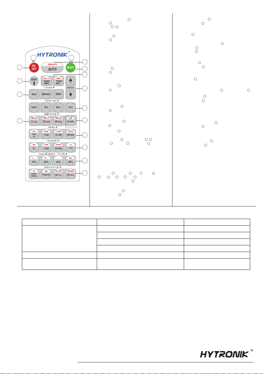
8.
Descriptions of the
Button Functions
(remote control HRC-11)
9. Troubleshooting
MALFUNCTION CAUSE REMEDY CAUSE REMEDY
The fixture does not light up
The fixture is always on
Check detection area setting
The fixture is on when it should not
Incorrect daylight threshold setting
Continous movement in the detection zone
Sudden change in temperature due to weather (wind, rain, snow) or air
expelled from fans, open windows
Detection zone not targeted
Faulty fixture
No power supply
Adjust daylight threshold setting
Replace fixture
Check power to sensor
Check detection area setting
Adjust zone, change installation site
Detection range [ zone ]
Press buttons in zone to set detection range at 100% / 75%
/ 50% / 10%.
8
8
Scene prog. [ zone ] (One-key-commissioning)
1. Press button “start” to program.
2. Select the buttons in “Detection range”, / “Daylight
hreshold”, “Hold time”, “Stand-by time”, “Stand-by
dimming level” to set all parameters.
3. Press button “Memory” to save all the settings programmed
in the remote control.
4. Press button “Apply” to set the settings to each sensor unit(s).
For example, to pre-set detection range 100%, daylight
threshold Disable, hold time 5min, stand-by time +∞,
stand-by dimming level 30%, the steps should be as follows:
Press button Start, button 100%, Disable, Shift,
5min, Shift, +∞, 30%, Memory. By pointing to
the sensor unit(s) and pressing Apply, all settings are
passed on the sensor(s).
7
7
7
7
3
3
8
8 9
10
10
11 1312
11 12 13
RESET[ button ]
2
2
Shift [ button ]
Press button , the LED on the top left corner will flash to indicate
mode selection.
All values / settings in RED are valid for 20 seconds.
3
3
Auto Mode [ button ]
Press button to initiate automatic mode. The sensor starts
working and all settings remain as before the light was switched
ON/OFF.
Note: the function of semi-auto is disabled.
4
4
Brightness +/- [ button ]
Press button to adjust the light brightness between 10%~100% .
6
6
Power output [ button ]
Press button , the light output shifts between 80% and 100%.
Note: the function of “Sensor off” and “Twilight” are disabled.
5
5
Permanent ON/OFF [ ]
Press button ,to select permanent ON or permanent OFF mode.
* Press button / to resume automatic operation.
The mode will change to AUTO Mode after power failure.
button
1
1
24
Press buttons in zone to set the daylight sensor at 2Lux / 10Lux /
50Lux / 100Lux / 300Lux / 500Lux or Disable.
Note: To set daylight sensor at 100Lux / 300 Lux / 500Lux, press
button Shift at first.
Daylight threshold [ zone ]
9
9
3
Ambient daylight threshold [ button ]
1. Press button Shift, the red LED is on for indication.
2. Press button , the ambient lux level is sampled and set as
the new daylight threshold.
3
10
10
Press buttons in zone to set the stand-by period at 0s / 10s /
1min / 5min / 10min / 30min / 1h / +∞.
Note: “0s” means on/off control; “+∞” means bi-level control,
100% on when motion detected, and remains at the stand-by
dimming level when no presence after hold-time.
Stand-by time [ zone ]
12
12
3
11
Hold time [ zone ]
Press buttons in zone to set the hold time at 2s / 30s / 1min /
5min / 10min / 15min / 20min / 30min.
Note: 1.To set hold-time at 30s / 5min / 15min / 30min, press
button Shift at first.
2. 2s is for testing purpose only, stand-by period and
daylight sensor settings are disabled in this mode.
*To exit from Test mode, press button or any button in zone .
11
11
2
Stand-by dimming level [ zone ]
Press buttons in zone to set the stand-by dimming level at
10% / 20% / 30% / 50%.
Note.the function of 24h / 12h / 4h / 30s are disabled.
13
13
Dual tech & RF mode [ zone ]
1. Press buttons in zone to select sensor technology.
HF+PIR: Light is on when both HF and PIR sensors are activated.
HF/PIR: Light is on when HF or PIR sensors are activated.
2. Short press button "Learn/Erase" to activate pairing mode on all
receiver (slave) units to be paired.
Note:up to 30 units can be paired.
3. Short press button "Transmit" at the commander unit(master), the
LED will flash for 3 times to indicate that the transmission signal has
been sent. The receiver units flashes slowly to indicate the success
of pairing. Repeat this process for two way communications, a single
sensor may act as both commander and receiver.
4. Long press “Learn/Erase” button for 3s, and the receiver unit
clears all commands it has received before.
5. Press button RX100%, the light on receiver unit is 100% on upon
receiving RF on signal; Press “RX STBY%” button, the light(s) goes
to presset stand-by dimming level directly.
14
14
6
8
11
12
13
2
4
1
3
7
9
5
HRC-11
&
A
4 hh
4
h
10
14
Press button , all settings go back to the default setting:
HIM39RF:Detection range:100%, hold time:1min,
stand-by time:5min,stand-by dimming level:20%,
daylight sensor:lux disable, RX 100%
HC034RF: Detection range:100%, hold time:10min,
stand-by time:30min,stand-by dimming level:20%,
daylight sensor:lux disable, RX 100%

Other manuals for HIM39/RF

1

This manual suits for next models

1

Other Hytronik Accessories manuals

Hytronik HBHC25 Quick guide

Hytronik

Hytronik HBHC25 Quick guide

Hytronik HC005S/IR Quick guide

Hytronik

Hytronik HC005S/IR Quick guide

Hytronik HC419VRC User manual

Hytronik

Hytronik HC419VRC User manual

Hytronik HC419VRC/R User manual

Hytronik

Hytronik HC419VRC/R User manual

Hytronik HC419V User manual

Hytronik

Hytronik HC419V User manual

Hytronik HIR28 User manual

Hytronik

Hytronik HIR28 User manual

Hytronik HC005S/BT Quick guide

Hytronik

Hytronik HC005S/BT Quick guide

Hytronik HC403VRC-KD/I User manual

Hytronik

Hytronik HC403VRC-KD/I User manual

Hytronik HN020-01V User manual

Hytronik

Hytronik HN020-01V User manual

Hytronik HC005S/I Quick guide

Hytronik

Hytronik HC005S/I Quick guide

Hytronik HMW35 Quick guide

Hytronik

Hytronik HMW35 Quick guide

Hytronik HIM32 Quick guide

Hytronik

Hytronik HIM32 Quick guide

Hytronik HIR23 Quick guide

Hytronik

Hytronik HIR23 Quick guide

Hytronik HCD418/DH User manual

Hytronik

Hytronik HCD418/DH User manual

Hytronik HC403VRC-KD User manual

Hytronik

Hytronik HC403VRC-KD User manual

Hytronik HMW24 User manual

Hytronik

Hytronik HMW24 User manual

Hytronik HMW12 Quick guide

Hytronik

Hytronik HMW12 Quick guide

Hytronik HC005S/BT Quick guide

Hytronik

Hytronik HC005S/BT Quick guide

Hytronik HEC7028 User manual

Hytronik

Hytronik HEC7028 User manual

Hytronik HIM31 Quick guide

Hytronik

Hytronik HIM31 Quick guide

Hytronik HC005S/BT Quick guide

Hytronik

Hytronik HC005S/BT Quick guide

Hytronik HIM38/RF Quick guide

Hytronik

Hytronik HIM38/RF Quick guide

Hytronik HIM30 User manual

Hytronik

Hytronik HIM30 User manual

Hytronik HEC7428 User manual

Hytronik

Hytronik HEC7428 User manual

Popular Accessories manuals by other brands

Bogen ZPM-3 install guide

Bogen

Bogen ZPM-3 install guide

CONCORD Slider Instruction for attachment and use

CONCORD

CONCORD Slider Instruction for attachment and use

National Instruments WSN-3230 USER GUIDE AND SPECIFICATIONS

National Instruments

National Instruments WSN-3230 USER GUIDE AND SPECIFICATIONS

Siko MSAC506 quick start guide

Siko

Siko MSAC506 quick start guide

Pitney Bowes F680 Operator's manual

Pitney Bowes

Pitney Bowes F680 Operator's manual

Black Nova ARIA user manual

Black Nova

Black Nova ARIA user manual

Orno OR-AE-1310 Operating and instalation instructions

Orno

Orno OR-AE-1310 Operating and instalation instructions

GE PRV02 Owner's Manual & Installation Instructions

GE

GE PRV02 Owner's Manual & Installation Instructions

Bosch PRS-1AIP1 operating manual

Bosch

Bosch PRS-1AIP1 operating manual

PCB Piezotronics ICP 137B22A Installation and operating manual

PCB Piezotronics

PCB Piezotronics ICP 137B22A Installation and operating manual

fontastic Kari 10 user manual

fontastic

fontastic Kari 10 user manual

American Standard Acrylux Shower Base 4834Y1.ST Product features

American Standard

American Standard Acrylux Shower Base 4834Y1.ST Product features

Gin Gliders Camino Assembly manual

Gin Gliders

Gin Gliders Camino Assembly manual

Pivot Breath Sensor quick start guide

Pivot

Pivot Breath Sensor quick start guide

MESTIC MAC-40 Instructions for use

MESTIC

MESTIC MAC-40 Instructions for use

GS STAUFF OCS manual

GS

GS STAUFF OCS manual

Atom AT4100/PIR instruction manual

Atom

Atom AT4100/PIR instruction manual

Safety Technology International STI-3610 quick start guide

Safety Technology International

Safety Technology International STI-3610 quick start guide

manuals.online logo
manuals.online logoBrands
  • About & Mission
  • Contact us
  • Privacy Policy
  • Terms and Conditions

Copyright 2025 Manuals.Online. All Rights Reserved.