I. Specifications
Rated Voltage: 12V (9-16V)
Rated Current: 20mA~200mA
Detecting Distance: Rear (0’ – 5’) Front (0’- 2.5’)
Ultrasonic Frequency: 40Khz
Working Temperature: -22°~176°F
II. Connection
1) Sensors should be 1.5 to 2.5 feet from the ground, and
4” to 7” inches apart from each other (depending on
vehicle application).
2) Install parking sensors by drilling holes out of the front
and back bumper with the supplied 18.5mm hole saw
bit (make sure when using the angle adapters the
thicker side is facing down, level with the ground and
the UP arrow on the back of the sensor is facing up),
and install parking assist sensors.
3) The rear sensors A/B/C/D should be installed from left
to right (looking at the bumper). This is also how they
should be plugged into the control box. (Example A:
left, B: mid-left, C: mid-right, D: right)
4) The front sensors E/F/G/H should be installed from
right to left (looking at the bumper). This is also how
they should be plugged into the control box. (Example
E: right, F: mid-right, G: mid-left, H: left)
5) Connect the RED wire to the +12 volt accessory wire.
6) Connect the BLUE wire to the +12 volt reverse light wire.
7) Connect the GRAY wire to the +12 volt brake light wire.
8) Connect the BLACK wire to a ground (a metal, non-
painted surface).
9) Plug that wiring harness into the parking sensor control
box (labeled power)
10) Plug the LED display into the parking sensor control box
(labeled display) and run the cable through the vehicle
and mount the LED display on the dashboard. (Avoid
placing cable where it can get pinched or damaged).
11) Mount the control box in rear of vehicle in a safe place
away from rain, heat or humidity.
NOTE:
1) The sensitivity of the sensors can be increased or
decreased. Turning the dial clockwise to turn down sensitivity
and turn counter-clockwise to turn up the sensitivity.
2) The parking sensors are not designed to be used in
vehicles with metal bumpers.
3) The parking sensors are paintable. There are small rings
included that will fit in the groove on the front of the
sensor. When painting, be sure to use these rings so
paint
does get into the grooves otherwise the sensors will not
work properly.
4) The parking sensor kit is used as a parking aid. Please use
your mirrors and look around to avoid hitting any object.
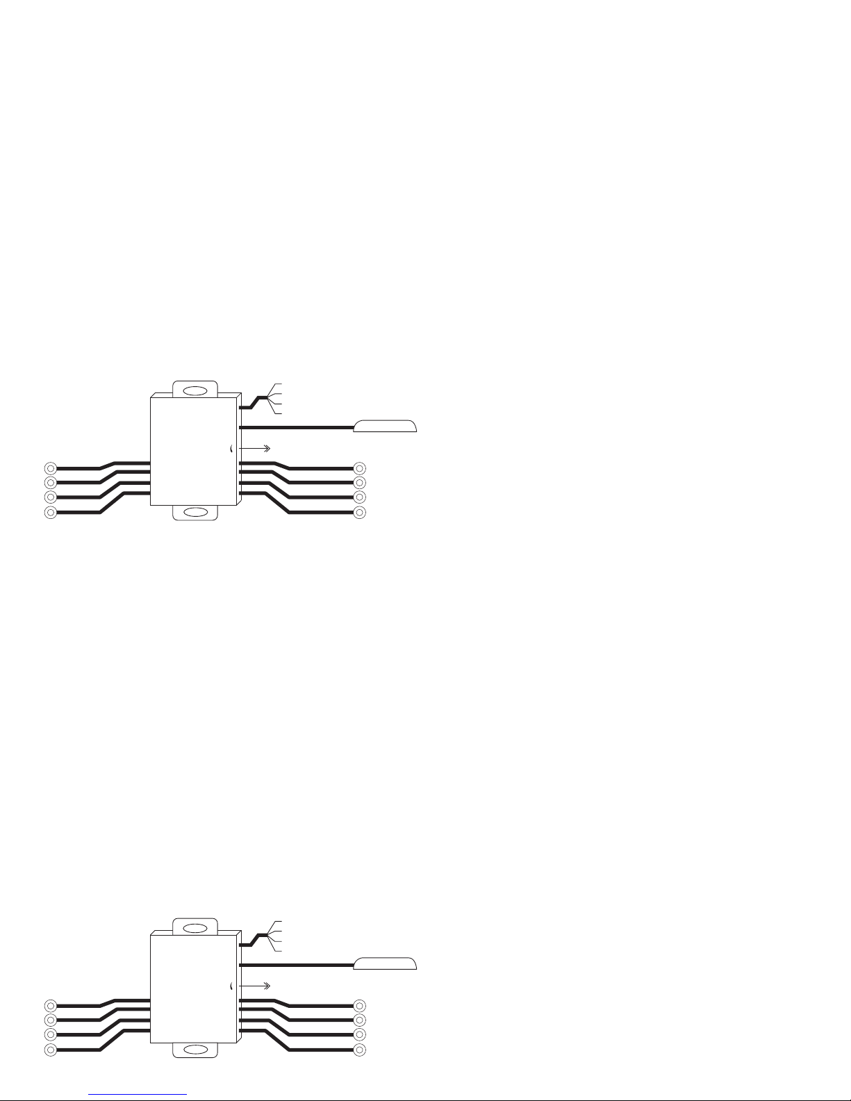
H G F E
A B C D
Display Power
Red Wire: 12 Volt Accessory (+)
Blue Wire: Reverse Light (+)
Gray Wire: Brake Light (+)
Black Wire: Ground
Detection Sensitivity Adjustable
Adj
Display
H G F E
H G F E
Display Power
Red Wire: 12 Volt Accessory (+)
Blue Wire: Reverse Light (+)
Gray Wire: Brake Light (+)
Black Wire: Ground
Detection Sensitivity Adjustable
Adj
Display
H G F E


