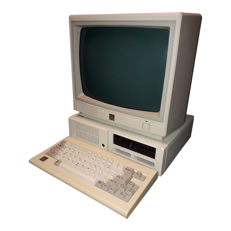
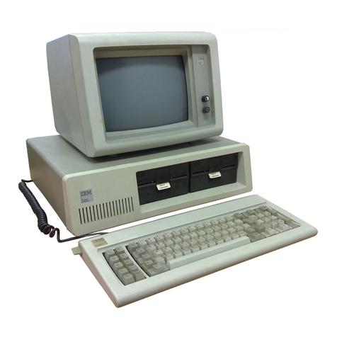
IBM AT 5170 Use and care manual


----
--
---
-
---
- -
---
-----
---
-Personal Computer
---
---
Hardware Reference
--_.-
Library
Technical
Reference

First Edition (September, 1985)
The following paragraph does not apply to the United
Kingdom
or
any country where such
provisions are inconsistent
with
local
law:
INTERNATIONAL BUSINESS MACHINES
CORPORATION PROVIDES THIS PUBLICATION "AS IS" WITHOUT WARRANTY
OF
ANY KIND,
EITHER
EXPRESS
OR
IMPLIED, INCLUDING, BUT NOT
LIMITED TO,
THE
IMPLIED WARRANTIES
OF
MERCHANTABILITY
OR
FITNESS
FOR
A PARTICULAR PURPOSE. Some states do not allow disclaimer of
express
or
implied warranties
in
certain transactions, therefore, this statement may not
apply to you.
This publication could include technical inaccuracies
or
typographical errors. Changes are
periodically made
to
the information herein; these changes will be incorporated
in
new
editions of the publication. IBM may make improvements
and/or
changes in the
product(s)
and/or
the program(s) described in this publication
at
any time.
It
is
possible that this publication may contain reference to, or information about, IBM
products (machines and programs), programming,
or
services that are not announced in
your country. Such references
or
information must not be construed to mean that IBM
intends to announce such IBM products, programming,
or
services in your country.
Products are not stocked at the address below. Requests for copies
of
this publication and
for technical information about IBM Personal Computer products should be made to your
authorized IBM Personal Computer dealer,
mM
Product Center, or your IBM Marketing
Representative. .
The following paragraph applies only to the United States and Puerto Rico: A Reader's
Comment
Foml
is
provided at the back of this publication.
If
the form has been removed,
address comments to: IBM Corporation, Personal Computer, P.O. Box
l328-C,
Boca
Raton, Florida 33432. IBM may use or distribute any
of
the information you supply in
any way it believes appropriate without incurring any obligations whatever.
~
© Copyright International Business Machines Corporation 1985
Federal Communications Commission
Radio Frequency Interference Statement
Warning: The equipment described herein has
been
certified to comply with
the
limits for a Class B computing
device, pursuant to Subpart J
of
Part
15
of
the
FCC
rules.
Only peripherals (computer
input/output
devices, terminals,
printers, etc.) certified
to
comply with the Class B limits may
be
attached to
the
computer. Operation with non-certified
peripherals
is
likely
to
result in interference to radio and
TV
reception.
If
peripherals not offered by
mM
are used with
the
equipment, it
is
suggested
to
use shielded grounded cables
with in-line filters if necessary.
CAUTION
This product described herein
is
equipped with a grounded
plug for
the
user's safety.
It
is
to
be
used in conjunction with
a properly grounded receptacle
to
avoid electrical shock.
iii

Notes:
iv

Preface
This manual describes the various units of the IBM Personal
Computer AT and how they interact.
It
also has information
about the basic
input/output
system (BIOS) and about
programming support.
The information in this publication
is
for reference, and
is
intended for hardware and program designers, programmers,
engineers, and anyone else who needs to understand the design
and operation
of
the IBM Personal Computer AT.
This manual consists
of
nine sections:
• The first three sections describe the hardware aspects of the
IBM Personal Computer AT including signal charts and
register information.
• Section 4 describes keyboard operation, the commands to
and from the system, and the various keyboard layouts.
• Section 5 contains information about the usage of BIOS and
a system BIOS listing.
• Section 6 contains instruction sets for the 80286
microprocessor and the 80287 math coprocessor.
• Section 7 provides information about characters, keystrokes,
and colors.
• Section 8 has general communications information.
• Section 9 contains information about the compatibility of the
IBM Personal Computer AT and the rest of the IBM
Personal Computer family.
A glossary of terms and a bibliography of related publications are
included.
v

Prerequisite Publications
Guide to Operations for the IBM Personal Computer AT
Suggested Reading
•
BASIC
for the IBM Personal Computer
• Disk Operating System (DOS)
•
MA
CR
0 Assembler for the IBM Personal Computer
vi

Contents
SECTION 1. SYSTEM BOARD
.....•..•............
1-1
Memory
....................................
1-4
Microprocessor
...............................
1-4
System Performance
...........................
1-7
Direct Memory Access
.........................
1-9
System Interrupts
............................
1-12
Hardware Interrupt Listing
.................
1-13
Interrupt Sharing
.........................
1-14
System Timers
..............................
1-22
System Clock
...............................
1-23
ROM
Subsystem
.............................
1-23
RAM Subsystem
.............................
1-24
I/OChannel
................................
1-24
Connectors
.............................
1-25
I/O
Channel Signal Description
.............
1-31
NMI and Coprocessor Controls
.............
1-38
Other Circuits
...............................
1-40
Speaker
................................
1-40
RAM Jumpers
...........................
1-40
Display Switch
..........................
1-41
Variable Capacitor
.......................
1-41
Keyboard Controller
......................
1-42
Real-Time
Clock/CMOS
RAM Information
...
1-56
Specifications
...............................
1-69
System Unit
............................
1-69
Connectors
.............................
1-71
Logic Diagrams -Type 1
..................
1-76
Logic Diagrams -Type 2
..................
1-98
SECTION 2.
COPROCESSOR
......................
2-1
Description
..................................
2-3
Programming Interface
.........................
2-3
Hardware Interface
............................
2-4
SECTION 3.
POWER
SUPPLY
..•....•.........•....
3-1
Inputs
......................................
3-3
vii

Outputs
.....................................
3-4
DC
Output Protection
.........................
3-4
Output Voltage Sequencing
.....................
3-4
No-Load Operation
...........................
3-5
Power-Good Signal
............................
3-5
Connectors
..................................
3-7
SECTION 4. KEYBOARD
..........................
4-1
Description
..................................
4-3
Power-On Routine
............................
4-4
Commands from the System
.....................
4-5
Commands to the System
.......................
4-9
Keyboard Scan-Code Outputs
..................
4-11
Clock and
Data
Signals
........................
4-12
Keyboard Layouts
...........................
4-15
Specifications
...............................
4-22
Logic Diagram
..............................
4-23
SECTION 5. SYSTEM BIOS
..•.................•...
5-1
System BIOS Usage
...........................
5-3
Keyboard Encoding and Usage
..................
5-13
Quick Reference
.............................
5-24
SECTION 6. INSTRUCTION SET
...................
6-1
80286 Instruction Set
..........................
6-3
Data Transfer
............................
6-3
Arithmetic
...............................
6-6
Logic
...................................
6-9
String Manipulation
......................
6-11
Control Transfer
.........................
6-13
Processor Control
........................
6-17
Protection Control
.......................
6-18
80287 Coprocessor Instruction Set
...............
6-22
Data Transfer
...........................
6-22
Comparison
............................
6-23
Constants
..............................
6-24
Arithmetic
..............................
6-25
Transcendental
..........................
6-26
SECTION 7. CHARACTERS, KEYSTROKES, AND
COLORS
•..............••.....•••..•......•...
7-1
Character Codes
..............................
7-3
Quick Reference
.............................
7-14
viii

SECTION 8. COMMUNICATIONS
.•.••.....•..••.••
8-1
Hardware
...................................
8-3
Establishing a Communications Link
..............
8-5
SECTION 9. IBM PERSONAL COMPUTER
COMPATIBILITY
..........•.••..••.......••.•••
9-1
Hardware Considerations
.......................
9-3
System Board
............................
9-3
Fixed Disk Drive
..........................
9-5
Diskette Drive Compatibility
................
9-5
Copy Protection
..........................
9-5
Application Guidelines
.........................
9-7
High-Level Language Considerations
..........
9-7
Assembler Language Programming Considerations 9-8
Multitasking Provisions
....................
9-16
Machine-Sensitive Code
...................
9-19
Glossary
••.••.•..•..••••.•••..•..••••.••.••
Glossary-l
Bibliograpby
..•••••••••.••.•••••••••••...•
Bibliograpby-l
Index
........................................
Index-l
ix

Notes:
x

INDEX
TAB LISTING
Section
1:
System Board
...............................
.
Section 2: Coprocessor
................................
.
Section 3: Power Supply
...............................
.
Section 4: Keyboard
..................................
.
Section 5: System BIOS
...............................
.
Section 6: Instruction Set
..............................
.
xi

Notes:
xii

Section 7: Characters, Keystrokes, and Colors
..............
.
Section
8:
Communications
............................
.
Section 9: Compatibility
...............................
.
Glossary
...........................................
.
Bibliography
........................................
.
Index
..............................................
.
xiii

SystemBlockDiagram
System
Unit
System Board
80286 80287 Osci
llator
Power
Supply
Microprocessor
Coprocessor
115/230
16
Interrupt
ROM
Speaker Speaker
Levels
Connector
7 Channel
RAM
Keyboard Keyboard
DMA
Controller
CMOS
Real-Time
Battery
Battery
Clock Connector
Fixed
Diskette
Disk
Drives
Drives
I/O
Channel Fixed Disk and
00000000
Diskette
Adapter
DDDDD
D
xiv

SECTION
1.
SYSTEMBOARD
Contents
Memory
.................•...•............•.•..••
1-4
Microprocessor
................•..................
1-4
Real Address Mode
..........................
1-4'
Protected (Virtual Address) Mode
..............
1-5
System Performance
..•............•••.•....••.....
1-7
DirectMemory Access
.................•...•..•...•
1-9
System Interrupts
................................
1-12
Hardware Interrupt Listing
......................
1-13
Interrupt Sharing
..............................
1-14
Design Overview
...........................
1-14
Program Support
...........................
1-15
Precautions
...............................
1-17
Examples
.................................
1-18
System Tinters
.........•.........•.........••...•
1-22
System Clock
.......................••...........
1-23
ROM
Subsystem
1-23
RAM Subsystem
1-24
110 Channel
....................................
1-24
Connectors
..................................
1-25
110
Channel Signal Description
..................
1-31
NMI and Coprocessor Controls
..................
1-38
Other Circuits
.............•.•...........•...••..
1-40
Speaker
.....................................
1-40
RAM
Jumpers
................................
1-40
System Board 1-1

Display Switch
................................
1-41
Variable Capacitor
............................
1-41
Keyboard Controller
...........................
1-42
Keyboard Controller Initialization
..............
1-42
Receiving
Data
from
the
Keyboard
.............
1-43
Scan
Code
Translation
.......................
1-43
Sending
Data
to
the Keyboard
.................
1-48
Inhibit
...................................
1-48
Keyboard Controller System Interface
..........
1-48
Status Register
.............................
1-49
Status-Register Bit Definition
.................
1-49
Output
Buffer
.............................
1-50
Input
Buffer
...............................
1-51
Commands
(I/O
Address
Hex
64)
.............
1-51
I/O
Ports
.................................
1-54
Real-Time
Clock/CMOS
RAM
Information
........
1-56
Real-Time Clock Information
.................
1-57
CMOS
RAM
Configuration Information
.........
1-59
1/0 Operations
.............................
1-68
Specifications
•.......•.•........•....•........•.
1-69
System Unit
..................................
1-69
Size
.....................................
1-69
Weight
...................................
1-69
Power Cables
..............................
1-69
Environment
..............................
1-69
Heat
Output
...............................
1-70
Noise Level
...............................
1-70
Electrical
.................................
1-70
Connectors
..................................
1-
71
Logic Diagrams -Type 1
........................
1-76
Logic Diagrams -Type 2
........................
1-98
1-2
System Board

The type 1 system board
is
approximately 30.5 by 35 centimeters
(12 by 13.8 inches). The type 2 system board
is
approximately
23.8 by 35 centimeters (9.3 by 13.8 inches). Both types
of
system boards use very large scale integration (VLSI) technology
and
have the following components:
• Intel 80286 Microprocessor
• System support function:
Seven-Channel Direct Memory Access (DMA)
Sixteen-level interrupt
Three programmable timers
System clock
• 64K read-only memory (ROM) subsystem, expandable to
128K
• A 512K random-access memory (RAM) Subsystem
.~
• Eight
input/output
(I/O)
slots:
Six with a 36-pin and a 62-pin card-edge socket
Two with only the 62-pin card-edge socket
• Speaker attachment
• Keyboard attachment
• Complementary metal oxide semiconductor (CMOS)
memory
RAM
to maintain system configuration
• Real-Time Clock
• Battery backup for CMOS configuration table and
~
Real-Time Clock
System
Board
1-3

Memory
The
type 1 system
board
has four banks
of
memory sockets, each
supporting 9 128K-by-1-bit modules for a total memory size of
512K, with parity checking.
~
The type 2 system board has two banks of memory sockets, each
supporting 9 256K-by-1-bit modules for a total memory size of
512K, with parity checking.
Microprocessor
The Intel 80286 microprocessor has a 24-bit address, 16-bit
memory interface1,
an
extensive instruction set,
DMA
and
interrupt support capabilities, a hardware fixed-point mUltiply
and
divide, integrated memory management, four-level memory
protection,
1G
(1,073,741,824 bytes)
of
virtual address space for
each task,
and
two operating modes: the 8086-compatible real
~
address mode and the protected
or
virtual address mode. More
detailed descriptions of the microprocessor may be found in the
publications listed in the Bibliography
of
this manual.
Real Address Mode
In
the real address mode, the microprocessor's physical memory
is
acontiguous array
of
up
to
one megabyte. The microprocessor
addresses memory
by
generating 20-bit physical addresses.
The selector portion
of
the pointer is interpreted as the upper 16
bits
of
a 20-bit segment address. The lower 4 bits
of
the 20-bit
segment address are always zero. Therefore, segment addresses
begin
on
multiples
of
16 bytes.
In
this manual, the
tenn
interface refers
to
a device that carries signals between
functional units.
1-4
System Board
Table of contents
Other IBM Desktop manuals

IBM
IBM 7012 G Series User manual

IBM
IBM 3196 Manual

IBM
IBM 92296GU - IntelliStation M - Pro 9229 User manual

IBM
IBM PC 300

IBM
IBM NetVista A20 User manual

IBM
IBM 865951Y - Netfinity 5000 - 51Y Owner's manual

IBM
IBM NetVista A21 Service manual

IBM
IBM BRUGERVEJLEDNING 8184 Technical document

IBM
IBM NetVista A22p User manual

IBM
IBM NetVista A30 User manual

IBM
IBM PS/2 65 SX Use and care manual

IBM
IBM NetVista X40 User manual

IBM
IBM NetVista A22p Quick start guide

IBM
IBM NetVista A21 User manual

IBM
IBM Power775 Manual

IBM
IBM NetVista S42 User manual

IBM
IBM 6565 - PC 300 PL User manual

IBM
IBM NetVista X40

IBM
IBM IntelliStation Z Pro User manual

IBM
IBM NetVista 6049 User manual