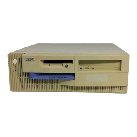
IBM PS/2 90 XP 486 Owner's manual

FRONT
PICTURE 1
Part Number 04G3388
Form Number S14F-2249-02
October 22, 1991
IBM PS/2 Model 90 XP 486 HMR
¦ Copyright IBM Corp. 1990, 1991
FRONT - 1

EDITION Edition Notice
Safety Information
Refer to the Hardware Maintenance Reference General Information
pamphlet for the following information:
General Safety
Electrical Safety.
Third Edition (October 1991)
The following paragraph does not apply to the United Kingdom or any
country where such provisions are inconsistent with local law:
INTERNATIONAL BUSINESS MACHINES CORPORATION PROVIDES THIS PUBLICATION
"AS IS" WITHOUT WARRANTY OF ANY KIND, EITHER EXPRESS OR IMPLIED,
INCLUDING, BUT NOT LIMITED TO, THE IMPLIED WARRANTIES OF
MERCHANTABILITY OR FITNESS FOR A PARTICULAR PURPOSE. Some states do
not allow disclaimer of express or implied warranties in certain
transactions, therefore, this statement may not apply to you.
This publication could include technical inaccuracies or typographical
errors. Changes are periodically made to the information herein;
these changes will be incorporated in new editions of the publication.
IBM may make improvements and/or changes in the product(s) and/or the
program(s) described in this publication at any time.
It is possible that this publication may contain reference to, or
information about, IBM products (machines and programs), programming,
or services that are not announced in your country. Such references
or information must not be construed to mean that IBM intends to
announce such IBM products, programming, or services in your country.
Requests for technical information about IBM products should be made
to your IBM Authorized Dealer or your IBM Marketing Representative.
IBM may have patents or pending patent applications covering subject
matter in this document. The furnishing of this document does not
give you any license to these patents. You can send license
inquiries, in writing, to the IBM Director of Commercial Relations,
IBM Corporation, Purchase, NY 10577.
¦ Copyright International Business Machines Corporation 1990, 1991.
All rights reserved.
Note to U.S. Government Users -- Documentation related to restricted
rights -- Use, duplication or disclosure is subject to restrictions
set forth in GSA ADP Schedule Contract with IBM Corp.
IBM PS/2 Model 90 XP 486 HMR
Edition Notice
¦ Copyright IBM Corp. 1990, 1991
EDITION - 1
FRONT_1 Special Notices
References in this publication to IBM products, programs, or services do
not imply that IBM intends to make these available in all countries in
which IBM operates. Any reference to an IBM product, program or service
is not intended to state or imply that only IBM's product, program, or
service may be used. Any functionally equivalent product, program, or
service that does not infringe any of IBM's intellectual property rights
or other legally protectible rights may be used instead of the IBM
product, program, or service. Evaluation and verification of operation in
conjunction with other products, programs, or services, except those
expressly designated by IBM, are the user's responsibility.
IBM may have patents or pending patent applications covering subject
matter in this document. The furnishing of this document does not give
you any license to these patents. You can send license inquiries, in
writing, to the IBM Director of Commercial Relations, IBM Corporation,
Purchase, NY 10577.
The following terms, denoted by an asterisk (*) in this publication, are
trademarks of the IBM Corporation in the United States and/or other
countries:
IBM
Personal System/2
Micro Channel
XP
XGA.
The following terms, denoted by a double asterisk (**) in this
publication, are trademarks of the Intel Corporation in the United States
and/or other countries:
486
487
SX.
IBM PS/2 Model 90 XP 486 HMR
Special Notices
¦ Copyright IBM Corp. 1990, 1991
FRONT_1 - 1

CONTENTS Table of Contents
EDITION Edition Notice
FRONT_1 Special Notices
CONTENTS Table of Contents
1.0 Product Description
1.1 Security
1.1.1 Cover Lock
1.1.2 Bolt-down Capability
1.1.3 Power-On Password
1.2 System Features
1.2.1 Processor Board
1.2.2 CMOS RAM and CMOS RAM Extension
1.2.3 IML, POST, and BIOS
1.2.4 Graphics Array
1.2.5 Serial Ports
1.2.6 Parallel Port
1.2.7 Diskette-Drive Controller
1.2.8 Keyboard Connector and Pointing Device Connector
1.3 System Memory
2.0 Option Compatibility
2.1 Drive and Diskette Compatibility
2.2 Hard Disk Drive
2.3 Terminators
3.0 Operating Requirements
3.1 Power Supply
4.0 Reference Diskette
4.1 Installing a New Version of the Reference Diskette
4.2 Making a Backup Copy of The System Partition
4.3 Diagnostic Programs and Information
5.0 Specifications
6.0 Special Tools
7.0 Removals and Replacements
7.1 1005 Cover
7.2 1010 Cover Lock
7.3 1015 Fan / Air Baffle
7.4 1020 Power Switch / Speaker Assembly
7.5 1025 Diskette Drive
7.6 1030 Hard Disk Drive
7.7 1035 Adapters
7.8 1040 487SX Processor (extended math capability)
7.9 1045 Memory-Riser-Card Bracket
7.10 1050 Memory-Riser Card
7.11 1055 Power Supply
7.12 1060 Battery
7.13 1065 System Board
7.14 1070 Video Memory
8.0 Locations
8.1 Front View
8.2 Rear View
8.3 Interior View
8.4 Internal Cables
8.5 System Board
8.6 Processor Board
9.0 Grounds
IBM PS/2 Model 90 XP 486 HMR
Table of Contents
¦ Copyright IBM Corp. 1990, 1991
CONTENTS - 1

1.0 Product Description
The IBM (*) Personal System/2 (*) Model 90 XP (*) 486 computers use the
IBM Micro Channel (*) architecture. The features of the various types of
the Model 90 are:
Security
- Cover lock
- Bolt-down capability
- Power-on password
System board
- Processor board (with a connector for L2 Cache)
- 80486 25-MHz processor board (math capability built in)
- 80486 33-MHz processor board (math capability built in)
- 80486 50-MHz processor board (math capability built in)
- Processor board (without a connector for L2 Cache)
- 80486SX (**) 20-MHz processor board (without math capability)
- 80487SX (**) 20-MHz processor board (math capability built in)
- 80486SX 25-MHz processor board (with an empty socket for an
80487SX processor with math capability)
- 64 byte complementary metal-oxide semiconductor (CMOS) random
access memory (RAM) with real-time clock and 2KB (KB = 1024 bytes)
CMOS RAM extension
- Two memory-riser cards: one card blank and one card with 4MB (MB
= 1 048 576 bytes) random access memory (RAM) (64MB total system
memory capacity)
- Graphics array
- Extended graphics array (XGA) (*) with 512KB expandable to 1MB
- Video graphics array (VGA) compatible
- Four expansion slots
- Three 32-bit expansion slots with matched memory extension
- One 32-bit expansion slot with auxiliary video extension
- Two serial ports
- Parallel port
- Diskette-drive controller
- Battery (to keep CMOS RAM active when power is off)
- Keyboard connector
- Initial Machine Loading (IML) supported
- Pointing-device connector
Power supply
- Automatically switches to the 100-125 V ac or the 200-240 V ac
range
- 50 or 60 Hz
Speaker and switch assembly
101/102-key keyboard
Small Computer System Interface (SCSI) adapter with internal and
external connectors
SCSI fixed disk drive (hard disk drive)
Diskette drive.
(*) IBM, Personal System/2, Micro Channel, XGA, and XP are
trademarks of the International Business Machines
Corporation.
(**) 486, 487, and SX are trademarks of the Intel Corporation.
Subtopics
1.1 Security
1.2 System Features
1.3 System Memory
IBM PS/2 Model 90 XP 486 HMR
Product Description
¦ Copyright IBM Corp. 1990, 1991
1.0 - 1

1.1 Security
Subtopics
1.1.1 Cover Lock
1.1.2 Bolt-down Capability
1.1.3 Power-On Password
IBM PS/2 Model 90 XP 486 HMR
Security
¦ Copyright IBM Corp. 1990, 1991
1.1 - 1

1.1.1 Cover Lock
The cover lock is in the middle of the rear panel of the system unit; the
cover can't be removed without the cover-lock key.
If the keys for the cover lock are lost, a new cover-lock assembly can be
ordered (see the parts section in the Hardware Maintenance Service for the
system you are servicing).
IBM PS/2 Model 90 XP 486 HMR
Cover Lock
¦ Copyright IBM Corp. 1990, 1991
1.1.1 - 1

1.1.2 Bolt-down Capability
The bolt-down capability allows you to attach the system unit to a table
or desk.
The table or desk must have holes drilled through it, and the bolts must
be inserted from below (the table or desk) into the holes in the base of
the system unit. There are three holes 1. The distance between the two
holes on the right side of the base is 165 mm
(6.5 in.).
Use 6 mm bolts. The length of the bolts should be 15 mm (0.60 in.) plus
the thickness of the table or desk.
PICTURE 2
IBM PS/2 Model 90 XP 486 HMR
Bolt-down Capability
¦ Copyright IBM Corp. 1990, 1991
1.1.2 - 1

1.1.3 Power-On Password
A power-on password denies access to the system by an unauthorized user
when the system is powered-on. When a power-on password is active, the
password prompt (which resembles a small key) appears on the screen each
time the system is powered-on (except when the system is in the Unattended
Start Mode). Access to the system occurs when the proper password is
entered.
To service a system with an active and unknown power-on password,
power-off the system and do the following:
1. Locate connector J10 on the system board (see "System Board" in
topic 8.5 for connector location).
2. Move the jumper on J10 so that it connects the center pin and the pin
on the opposite end of the connector.
3. Power-on the system.
The system detects the change and the password is erased from memory.
Leave the jumper in that position until the next time you need to reset
the password.
To reinstall a password, the user must start the system, select Set
features from the Main Menu, and follow the instructions.
IBM PS/2 Model 90 XP 486 HMR
Power-On Password
¦ Copyright IBM Corp. 1990, 1991
1.1.3 - 1

1.2 System Features
The major features of the system include:
Processor board
CMOS RAM and CMOS RAM Extension
Initial Machine Load (IML)
Power-On Self-Test (POST)
Basic Input/Output System (BIOS)
Graphics array (VGA and XGA)
Serial ports (2)
Parallel port
Diskette-drive controller
Keyboard connector
Pointing-device connector.
Subtopics
1.2.1 Processor Board
1.2.2 CMOS RAM and CMOS RAM Extension
1.2.3 IML, POST, and BIOS
1.2.4 Graphics Array
1.2.5 Serial Ports
1.2.6 Parallel Port
1.2.7 Diskette-Drive Controller
1.2.8 Keyboard Connector and Pointing Device Connector
IBM PS/2 Model 90 XP 486 HMR
System Features
¦ Copyright IBM Corp. 1990, 1991
1.2 - 1

1.2.1 Processor Board
The processor board is connected to the system through two dedicated
in-line system-board connectors. The major components on the processor
board are the system microprocessor, the system clock, the direct memory
access (DMA) controller, and the memory controller.
The system microprocessor is a 32-bit microprocessor that operates in the
real-address mode or in the virtual-address (protected) mode.
The amount of memory supported and the clock speed vary with the type of
processor board installed.
IBM PS/2 Model 90 XP 486 HMR
Processor Board
¦ Copyright IBM Corp. 1990, 1991
1.2.1 - 1

1.2.2 CMOS RAM and CMOS RAM Extension
The CMOS RAM provides 64 bytes of storage. Fifty bytes are used to store
system-configuration and security information. The real-time clock uses
the remaining 14 bytes to track the date, time, and battery level. A 2KB
CMOS RAM extension stores additional configuration and system-status
information.
The data stored in the CMOS RAM and CMOS RAM extension is kept active by
the battery when the system is powered-off. If the stored data is lost
due to a depleted or removed battery, the data can be restored using one
of the following methods:
If the user has a customized configuration that uses settings other
than the default, run Restore configuration from the system programs
stored on the default hard disk drive.
If default configuration settings are used, run Automatic
configuration from the system programs stored on the hard disk drive.
IBM PS/2 Model 90 XP 486 HMR
CMOS RAM and CMOS RAM Extension
¦ Copyright IBM Corp. 1990, 1991
1.2.2 - 1

1.2.3 IML, POST, and BIOS
The Model 90 uses Initial Machine Load (IML) to store the power-on
self-test (POST) and Basic Input/Output System (BIOS) code. With IML,
some of the code is stored in ROM and is used for preliminary testing
during power-on; but the balance of the POST and BIOS code, called the IML
image, is stored in a protected partition on the default hard disk drive.
This IML image is loaded onto the default hard disk drive at the time the
system is manufactured.
At power-on, the first stage of POST is started from ROM. During this
first stage, POST performs the following functions:
Checks some basic system-board and processor-board functions
Initializes the video function
Checks the memory subsystem
Verifies that the default hard disk drive is functioning
Verifies that the IML image is copied in the protected partition of
the default hard disk drive.
When the first stage of POST is complete, the IML image is loaded into RAM
from the protected partition on the default drive. The second stage of
POST is started from RAM. It performs additional tests of the hardware
and initializes the system. When the second stage of POST is complete,
system control is given to the operating system.
The partition also includes the system programs and the customer and
advanced diagnostic programs. The partition is not affected when the
drive is formatted using the operating system Format command.
Errors During POST: If the POST detects a problem, an eight-digit error
code is displayed.
Replacing the Default Hard Disk Drive: If you replace the default hard
disk drive, you must recopy all of the files onto the replacement hard
disk drive. To recopy the files:
1. Start the system using the customer's backup copy of the current
system partition.
Warning: This will write over all of the files in the system
partition. Before you do this, you must either have a complete
current backup copy of the system partition or all of the option
diskettes so you can recopy the option files.
2. Select Backup/Restore system programs from the Main Menu.
3. Run Restore System Partition to load the IML image, the system
programs, and the customer and advanced diagnostic programs onto the
system partition.
Notes:
1. If the user's backup copy of the system partition is incomplete, you
will not completely restore the system partition. If this is the
case, after you have recopied the IML image get the option diskettes
and use Copy an option to recopy the option files onto the partition.
2. If the IML image has been loaded onto the hard disk drive but the
customer's operating system has not been loaded, the Insert Diskette
icon will appear on the display.
For information on system programs, see the Diagnostic Information for
Micro Channel Computers pamphlet.
IBM PS/2 Model 90 XP 486 HMR
IML, POST, and BIOS
¦ Copyright IBM Corp. 1990, 1991
1.2.3 - 1

1.2.4 Graphics Array
The graphics array is located on the system board and operates in two
video modes:
1. VGA compatibility mode
2. XGA compatibility mode.
The system comes with at least four video-memory modules (512KB)
installed. Four additional sockets are available for installing
additional video-memory modules (maximum video memory is 1MB). When the
system is powered-on, the graphics array is in the VGA mode. In this
mode, all VGA alphanumeric text, and all-points-addressable (APA) graphics
video modes are supported. The maximum resolution in VGA compatibility
mode is 720-by-400 picture elements (PELS) in the text mode, and
640-by-480 PELS in the graphics mode. A maximum of 256 colors or 64
shades of gray is supported in VGA mode. Composite video is not
supported.
The graphics array is in the XGA mode only when enabled by the DOS Adapter
Interface or video device driver (example: MS Windows, OS/2 Presentation
Manager device drivers).
The XGA works with monochrome and color-analog direct-drive displays.
XGA supports the following:
+------------------------------------------------------------------------+
¦ System Board Video ¦ Resolution ¦ Colors ¦
¦ Memory ¦ ¦ ¦
+-----------------------+------------------------+-----------------------¦
¦ Four video modules ¦ 640 x 480 ¦ 256 16 ¦
¦ installed (512KB) ¦ or ¦ ¦
¦ ¦ 1024 x 768 ¦ ¦
+-----------------------+------------------------+-----------------------¦
¦ Eight video modules ¦ 640 x 480 ¦ 256 ¦
¦ installed (1MB) ¦ ¦ ¦
+------------------------------------------------------------------------+
The system board has a dedicated 32-bit expansion slot for video adapter
cards. This slot (J3) includes the auxiliary video connector (AVC) and
connects the VGA compatible video from the XGA (on the system board) to
video adapters (example: IBM PS/2 Image Adapter/A - 1MB).
IBM PS/2 Model 90 XP 486 HMR
Graphics Array
¦ Copyright IBM Corp. 1990, 1991
1.2.4 - 1

1.2.5 Serial Ports
The serial ports are fully programmable and support asynchronous
communications. The 9-pin and 25-pin D-shell connectors provide the
signals to drive devices with a standard RS-232 connector. The connected
device is identified by the system configuration as SERIAL 1 through
SERIAL 8. Conflicts occur when two or more devices have the same address.
Select the Set configuration option from the system programs stored on the
hard disk drive. Select View configuration to verify that no lines are
addressed the same.
IBM PS/2 Model 90 XP 486 HMR
Serial Ports
¦ Copyright IBM Corp. 1990, 1991
1.2.5 - 1

1.2.6 Parallel Port
The parallel port allows the attachment of devices that accept eight bits
of parallel data at standard transistor-transistor-logic (TTL) levels.
The port has a 25-pin D-shell connector and is designed primarily for
printers. However, the port can be used as an input/output port for any
device or application that matches the input/output capabilities of the
port. When adapters with additional parallel ports are installed, the
system can support these devices, each addressed separately as PARALLEL 1,
PARALLEL 2, PARALLEL 3, or PARALLEL 4.
Note: Conflicts occur when two or more devices have the same address.
Select the Set configuration option from the system programs stored
on the hard disk drive. Select View configuration to verify that
no lines have the same address.
IBM PS/2 Model 90 XP 486 HMR
Parallel Port
¦ Copyright IBM Corp. 1990, 1991
1.2.6 - 1

1.2.7 Diskette-Drive Controller
The diskette-drive controller is on the system board. The controller
connects to the diskette drives through a 34-pin cable connector (the
connector on the system board is a 40-pin cable-connector). Signals and
voltages are supplied through the diskette-drive cable that plugs into the
connector. These signals and voltages can operate a maximum of three
devices.
IBM PS/2 Model 90 XP 486 HMR
Diskette-Drive Controller
¦ Copyright IBM Corp. 1990, 1991
1.2.7 - 1

1.2.8 Keyboard Connector and Pointing Device Connector
The two 6-pin connectors in the rear of the system board are for a
keyboard and a pointing device (mouse). The keyboard connector is marked
on the back panel of the system unit with a small keyboard. The pointing
device connector is marked with a mouse symbol. The interface logic is
the same for both and they are interchangeable.
IBM PS/2 Model 90 XP 486 HMR
Keyboard Connector and Pointing Device Connector
¦ Copyright IBM Corp. 1990, 1991
1.2.8 - 1

1.3 System Memory
The figure below shows the location of the memory-module-kit connectors J4
to J1 on the memory-riser cards.
PICTURE 3
Two memory-riser cards plug into the system board; one in system-board
slot J11 and one in J14. Each memory-riser card has four slots numbered
J1 through J4, with J1 located at the bottom of the card. The system can
support up to 64MB of memory on the memory-riser cards, but the amount of
memory accessed may be limited by the operating system.
Memory Requirements and Limitations: Whenever memory is added or removed
from the system, run Set Configuration from the Main Menu. If memory
failed and then the customer runs customer diagnostics, the advanced
diagnostics will not detect the failing memory. After defective memory is
replaced, run the advanced diagnostic memory test or the system will not
not recognize the replacement memory.
The memory operates differently depending on which processor board is
installed. Systems can be upgraded with a different processor board than
the type indicated on the system serial number label. To verify which
board is installed, you must start the system programs and select Display
Revision Levels from the Main Menu. Make note of the submodel code
displayed on the screen.
The following indicates the memory configurations supported and which
system memory section to refer to.
+------------------------------------------------------------------------+
¦ Submodel Code ¦ Interleaved ¦ Noninterleaved ¦ System Memory ¦
¦ ¦ Supported ¦ Supported ¦ Type ¦
+-----------------+------------------+-----------------+-----------------¦
¦ ¦ ¦ ¦ ¦
¦ 11 ¦ Yes ¦ No ¦ Type 1 ¦
¦ 13 ¦ Yes ¦ No ¦ Type 1 ¦
¦ 2D ¦ Yes ¦ No ¦ Type 1 ¦
¦ 2F ¦ Yes ¦ No ¦ Type 1 ¦
¦ 2B ¦ Yes ¦ No ¦ Type 1 ¦
¦ 57 ¦ Yes ¦ Yes ¦ Type 2 ¦
¦ 59 ¦ Yes ¦ Yes ¦ Type 2 ¦
¦ ¦ ¦ ¦ ¦
+------------------------------------------------------------------------+
Interleaved Memory: An interleaved-memory configuration requires matched
pairs of memory-module kits (the size and the speed must be the same).
The kits must be installed in the following order: (starting with the J11
memory-riser card) pair J1, J3 then pair J2, J4. and so forth. This
technique of addressing memory in pairs enhances performance.
Noninterleaved Memory: A noninterleaved-memory configuration does not
require matched pairs of memory-module kits (the size and speed does not
have to be the same). Noninterleaved memory runs less efficiently than
interleaved memory but will allow mixed sizes of memory to be used.
Type 1 systems support interleaved-memory configurations only.
Type 2 systems support interleaved, noninterleaved, or a combination of
both configurations.
Memory Errors (Type 1 Systems): Some memory errors will cause a blank
display screen. If the display screen is blank, a POST error code can't
be displayed. The factory-installed 2MB kits (pair J1 and J3 on the
memory-riser card in slot J11) are divided into two banks and are
addressed as follows:
The first 1MB bank of J1 and the first 1MB bank of J3 are the first
block
The second 1MB bank of J1 and the second 1MB bank of J3 are the second
block.
Any other pairs of memory-module kits (for example J2, J4,) are addressed
in the same way; however, the block size depends on the memory kits
installed.
When any defective memory is detected in a bank, the entire block is
disabled.
The following figure shows an example of how memory disabling (after a
memory failure) varies depending on the memory configuration.
IBM PS/2 Model 90 XP 486 HMR
System Memory
¦ Copyright IBM Corp. 1990, 1991
1.3 - 1

+------------------------------------------------------------------------+
¦ Paired Memory ¦ Memory Bank Size ¦ Memory Block ¦ Memory Now ¦
¦ Kits ¦ ¦ Disabled ¦ Usable ¦
+-----------------+------------------+-----------------+-----------------¦
¦ ¦ ¦ ¦ ¦
¦ J1 J3 ¦ J1 J3 ¦ ¦ ¦
¦ 1MB 1MB ¦ 1MB 1MB ¦ 2MB ¦ 0MB ¦
¦ 2MB 2MB ¦ 1MB 1MB ¦ 2MB ¦ 2MB ¦
¦ 4MB 4MB ¦ 4MB 4MB ¦ 8MB ¦ 0MB ¦
¦ 8MB 8MB ¦ 4MB 4MB ¦ 8MB ¦ 8MB ¦
¦ ¦ ¦ ¦ ¦
+------------------------------------------------------------------------+
Minimum memory-block size is 2MB for 1MB and 2MB memory-module kits and
8MB for larger memory-module kits.
Note: If a system with only two 1MB kits (one 2MB block) or two 4MB kits
(one 8MB block) installed detects a memory problem, all
system-board memory will be disabled. (These are not standard
configurations and should be avoided.)
If the POST detects an error in the first block of system-board memory,
that block is disabled. If additional system-board memory is installed,
the addresses assigned to the deactivated blocks are reassigned to the
next usable block of system-board memory and a POST error code is
displayed.
If an additional block of system-board memory is installed, the
customer-level diagnostic programs (on the default hard disk drive) can be
run to deactivate the defective block and reassign the memory addresses.
The system can then operate with reduced memory capacity. The defective
block will then be ignored by POST during subsequent power-on operations.
If an additional block of system-board memory is not installed, no address
reassignment can occur and the system can't be used.
Memory Errors (Type 2 Systems): Some memory errors will cause a blank
display screen. If the display screen is blank, a POST error code can't
be displayed.
If the memory is installed in an interleaved configuration, the system
will operate as described under Memory (Type 1 systems); however, memory
errors are handled differently. If an error occurs in an interleaved
memory configuration, the pair of memory module kits containing the error
will automatically be switched to noninterleaved operation to keep the
maximum amount of memory active. Only the failing bank of memory will be
disabled.
The following figure shows how the amount of memory that is disabled
varies depending on the size of the memory-module kit installed.
+------------------------------------------------------------------------+
¦ Memory Module Kit installed ¦ Memory Bank Size Disabled ¦
+------------------------------------+-----------------------------------¦
¦ ¦ ¦
¦ 2MB ¦ 1MB ¦
¦ 4MB ¦ 4MB ¦
¦ 8MB ¦ 4MB ¦
¦ ¦ ¦
+------------------------------------------------------------------------+
Note: If a system with only one 1MB kit or one 4MB kit installed detects
a memory failure, all system-board memory will be disabled. (These
are not standard configurations and should be avoided.)
If the POST detects an error in the first bank of system-board memory,
that bank is disabled. If additional system-board memory is installed,
the addresses assigned to the deactivated banks are reassigned to the next
usable bank of system-board memory and a POST error code is displayed.
If an additional bank of system-board memory is installed, the
customer-level diagnostic programs (on the default hard disk drive) can be
run to deactivate the defective bank and reassign the memory addresses.
The system can then operate with reduced memory capacity. The defective
bank will then be ignored by POST during subsequent power-on operations.
If additional system-board memory is not installed, no address
reassignment can occur and the system can't be used.
IBM PS/2 Model 90 XP 486 HMR
System Memory
¦ Copyright IBM Corp. 1990, 1991
1.3 - 2
Other manuals for PS/2 90 XP 486
1
Table of contents
Other IBM Desktop manuals

IBM
IBM x3400 M2 7836 User manual

IBM
IBM NetVista A30 User manual

IBM
IBM PS/2 25 SX Owner's manual

IBM
IBM PC/2 Series Owner's manual

IBM
IBM IntelliStation 6836 Owner's manual

IBM
IBM IntelliStation Z Pro 6221 User manual

IBM
IBM Aptiva E2270 User manual

IBM
IBM IntelliStation Z Pro 6223 User manual

IBM
IBM 60 Use and care manual

IBM
IBM NetVista A22p User manual

IBM
IBM 3270 User manual

IBM
IBM NetVista X40 Setup guide

IBM
IBM PC 300 Mounting instructions

IBM
IBM 8863 - eServer xSeries 366 User manual

IBM
IBM System x3200 M3 User manual

IBM
IBM 265 User manual

IBM
IBM PC 300GL Types 6275 User manual

IBM
IBM NetVista A22p Service manual

IBM
IBM PC 300 User manual

IBM
IBM PC 300 User manual