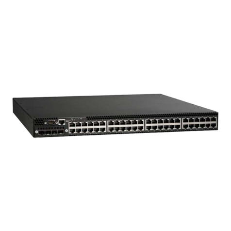
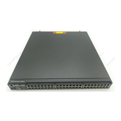
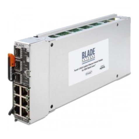
8271 NWAYS ETHERNET LAN SWITCH
MODELS E12 AND E24
QUICK REFERENCE GUIDE
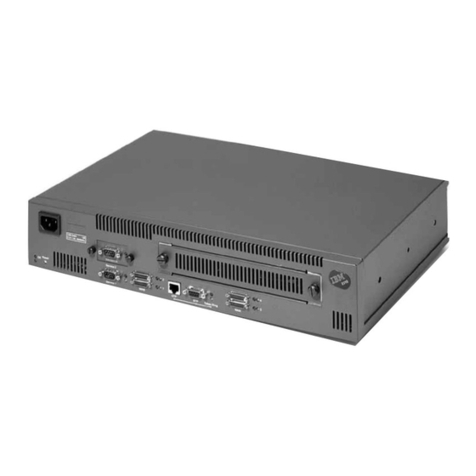
Hardware Features
Illustration shows Model E24 (24-port model). Port and
LED layout is different for Model E12 (12-port model).
110BASE-T Ports These ports provide a 10Mbps bandwidth
to Ethernet devices. The ports are configured as MDIX
(cross-over) and support a maximum segment length of
100m (328ft) over Category 3, 4 or 5 twisted pair cable.
2Status LEDs Status LEDs provide a quick method of diag-
nosing problems. See “LEDs” for more information.
310BASE-T/100BASE-TX Ports These auto-negotiating ports
can automatically detect the speed of a link and provide a
10Mbps connection to Ethernet devices or a 100Mbps con-
nection to Fast Ethernet devices. These ports are config-
ured as MDIX (cross-over) and support a maximum segment
length of 100m (328ft) over Category 5 twisted pair cable.
4Unit LEDs Unit LEDs indicate the position of this unit in the
stack.
5Power Socket Insert the power cord into this socket to
connect the Switch to the main power supply. Note that
there is no On/Off button.
6Redundant Power System (RPS) Socket Use this socket
to connect an RPS to the Switch, and protect against inter-
nal power supply failure.
7Console Port Use this port to connect a terminal or termi-
nal emulator to the Switch, and therefore allow out-of-band
management. The console port uses standard null modem
cable and is set to auto-baud, 8 data bits, no parity, and 1
stop bit.
8Expansion Module Slot Remove the blanking plate to
install an optional Expansion Module that provides an addi-
tional high-speed link, or a Matrix Module that provides
four matrix ports for stacking up to four units.
9Matrix Port Use this port to stack two units with a single
Matrix Cable, or use in conjunction with a Matrix Module
and multiple Matrix Cables to stack up to four units.
10 Transceiver Module Slot Remove the blanking plate to
install a transceiver module and provide a 10Mbps connec-
tion. Transceiver modules are available for a wide range of
media support. Contact your local supplier.
TCVR
green
flashinggreen
off
= enabled,linkOK
= disabled,linkOK
= linkfail
Status
Module
Unit
10BASE-T/100BASE-TX
3
3
4
4
5
56
6
7
7
8
8
9
9
10
10
11
11
12
12
1
1
2
23
5
1
4
7
6
8
2
13
13
14
14 15
15
16
16
17
17 18
18
19
19
20
20
21
21
22
22
23
23
24
24
25 26 PacketPacket
Packet
25 26 Status
Status
Status Power/Selftest
6x 7x
18x 19x
1x
13x
25x 26x
12x
24x
