manuals.online logo
Brands
  1. Home
  2. •
  3. Brands
  4. •
  5. IBM
  6. •
  7. Network Router
  8. •
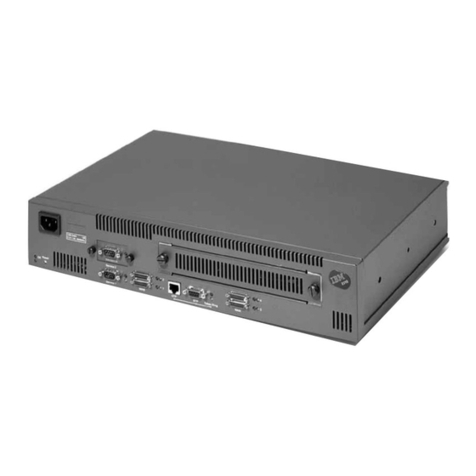
  9. IBM 2220 Nways 300 User manual

IBM 2220 Nways 300 User manual

This manual suits for next models

2

Other IBM Network Router manuals

IBM BC-201 User manual

IBM

IBM BC-201 User manual

IBM s-series User manual

IBM

IBM s-series User manual

IBM 51 User manual

IBM

IBM 51 User manual

IBM RackSwitch G7028 User manual

IBM

IBM RackSwitch G7028 User manual

IBM Bridge/ Heritage User manual

IBM

IBM Bridge/ Heritage User manual

IBM SAN04M-R Manual

IBM

IBM SAN04M-R Manual

IBM IBM 2212-40H User manual

IBM

IBM IBM 2212-40H User manual

IBM BBI User manual

IBM

IBM BBI User manual

IBM TotalStorage SAN16M-R SAN Manual

IBM

IBM TotalStorage SAN16M-R SAN Manual

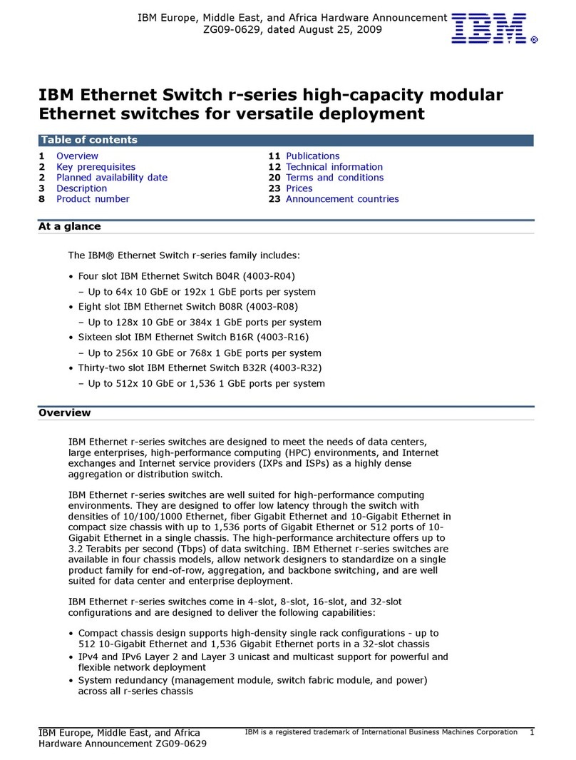
IBM Ethernet Switch r-series User manual

IBM

IBM Ethernet Switch r-series User manual

IBM RackSwitch G8000 User guide

IBM

IBM RackSwitch G8000 User guide

IBM SY27-0345-06 Installation and user guide

IBM

IBM SY27-0345-06 Installation and user guide

IBM B48Y User manual

IBM

IBM B48Y User manual

IBM RackSwitch G8264T User manual

IBM

IBM RackSwitch G8264T User manual

IBM Enterprise Console User manual

IBM

IBM Enterprise Console User manual

IBM 2210 User manual

IBM

IBM 2210 User manual

IBM J02M User manual

IBM

IBM J02M User manual

IBM SAN24B-R User manual

IBM

IBM SAN24B-R User manual

IBM F12 User manual

IBM

IBM F12 User manual

IBM BladeCenter 1/10 Gb Uplink Ethernet... User manual

IBM

IBM BladeCenter 1/10 Gb Uplink Ethernet... User manual

IBM J11M User manual

IBM

IBM J11M User manual

IBM Classic Series Planning guide

IBM

IBM Classic Series Planning guide

IBM m-series User manual

IBM

IBM m-series User manual

IBM 8364 E series User manual

IBM

IBM 8364 E series User manual

Popular Network Router manuals by other brands

TRENDnet TEW-435BRM - 54MBPS 802.11G Adsl Firewall M Quick installation guide

TRENDnet

TRENDnet TEW-435BRM - 54MBPS 802.11G Adsl Firewall M Quick installation guide

Siemens SIMOTICS CONNECT 400 manual

Siemens

Siemens SIMOTICS CONNECT 400 manual

Alfa Network ADS-R02 Specifications

Alfa Network

Alfa Network ADS-R02 Specifications

Barracuda Networks Link Balancer quick start guide

Barracuda Networks

Barracuda Networks Link Balancer quick start guide

ZyXEL Communications ES-2024PWR Support notes

ZyXEL Communications

ZyXEL Communications ES-2024PWR Support notes

HPE FlexNetwork 5510 HI Series Openflow configuration guide

HPE

HPE FlexNetwork 5510 HI Series Openflow configuration guide

Allied Telesis AT-AR236E quick start guide

Allied Telesis

Allied Telesis AT-AR236E quick start guide

ADTRAN NetVanta 3458-PoE quick start

ADTRAN

ADTRAN NetVanta 3458-PoE quick start

C&H Technologies EM405-8 manual

C&H Technologies

C&H Technologies EM405-8 manual

Huawei WiFi Mesh 3 Product description

Huawei

Huawei WiFi Mesh 3 Product description

Addonics Technologies ISC8P2G-S Quick install guide

Addonics Technologies

Addonics Technologies ISC8P2G-S Quick install guide

Atel W02 Arch+ Faqs

Atel

Atel W02 Arch+ Faqs

Allnet ALL0333AU user guide

Allnet

Allnet ALL0333AU user guide

Sercomm Genesis OC3505D Quick installation guide

Sercomm

Sercomm Genesis OC3505D Quick installation guide

Billion BIPAC 5102 Series user manual

Billion

Billion BIPAC 5102 Series user manual

TP-Link TD-8817 QIG

TP-Link

TP-Link TD-8817 QIG

Motorola MR1900 user guide

Motorola

Motorola MR1900 user guide

Cisco SOHO Series Regulatory compliance and safety information

Cisco

Cisco SOHO Series Regulatory compliance and safety information

manuals.online logo
manuals.online logoBrands
  • About & Mission
  • Contact us
  • Privacy Policy
  • Terms and Conditions

Copyright 2025 Manuals.Online. All Rights Reserved.

2220 Nways BroadBand Switch
Models 300, 500, and 501 IBM
Service Guide
SY33-2121-01
2220 Nways BroadBand Switch
Models 300, 500, and 501 IBM
Service Guide
SY33-2121-01
Note|
Before using this information and the product it supports, be sure to read the general information under “Notices” on page xi.
Second Edition (March 1999)
The information contained in this manual is subject to change from time to time. Any such changes will reported in subsequent
revisions.
Order publications through your IBM representative or the IBM branch office serving your locality. Publications are not stocked at the
address given below.
A form for readers' comments appears at the back of this publication. If the form has been removed, address your comments to:
IBM France
Centre d'Etudes et Recherches
Service 0798 - BP 79
06610 La Gaude
France
FAX: 33 4 93 24 77 97
IBM Internal Use: LGERCF at IBMFR
Internet: [email protected]
When you send information to IBM, you grant IBM a non-exclusive right to use or distribute the information in any way it believes
appropriate without incurring any obligation to you.
 Copyright International Business Machines Corporation 1998, 1999. All rights reserved.
Note to U.S. Government Users — Documentation related to restricted rights — Use, duplication or disclosure is subject to
restrictions set forth in GSA ADP Schedule Contract with IBM Corp.
Contents
Figures . . . . . . . . . . . . . . . . . . . . . . . . . . . . . . . . . . . . . . . . . vii
Tables . . . . . . . . . . . . . . . . . . . . . . . . . . . . . . . . . . . . . . . . . . . ix
Notices . . . . . . . . . . . . . . . . . . . . . . . . . . . . . . . . . . . . . . . . . . xi
European Union (EU) Statement ........................... xii
Year 2000 Statement ................................. xii
Electronic Emission Notices .............................. xii
Safety Notices for United Kingdom ........................ xiii
Safety Notice for Australia ............................. xiv
Telecommunication Connectivity Notices ...................... xiv
Notice to Users of Machines Installed in the U.S. ............... xiv
Notice to Users of Machines Installed in Canada ................ xv
Trademarks and Service Marks ........................... xvi
General and Product Safety ............................ xvii
Service Inspection Safety Procedures ........................ xvii
Safety and Disposal Instructions for Batteries ................... xvii
Service Inspection Safety Procedures ....................... xviii
Introduction . . . . . . . . . . . . . . . . . . . . . . . . . . . . . . . . . . . . . xviii
Sicherheitsüberprüfungen . . . . . . . . . . . . . . . . . . . . . . . . . . . . . . . xxv
Einführung . . . . . . . . . . . . . . . . . . . . . . . . . . . . . . . . . . . . . . xxv
Safety Label Locations .................................. xl
Safety Label Identifications .............................. xliv
About this Manual .................................. xlix
Aim of this Manual ................................... xlix
Who Should Read this Manual ............................ xlix
How this Manual is Organized ............................ xlix
Chapter 1. START - Finding a Service Procedure ............... 1-1
Service Operation via Nways Switch Administration Station ........... 1-2
Chapter 2. Introduction / Overview ........................ 2-1
Typical Broadband Network Based on 2220 .................... 2-1
2220 Models . . . . . . . . . . . . . . . . . . . . . . . . . . . . . . . . . . . . . . 2-2
2220 Control Panel Functions ............................ 2-3
Chapter 3. Nways Switch Administration Station Functions ........ 3-1
How to Start on the Local 2220 ........................... 3-1
How to Logon to the Remote 2220 ......................... 3-1
Nways Switch Administration Station Windows Overview ............. 3-5
How to Display the CMIP Status ........................... 3-8
How to Display the Alarm Desk .......................... 3-11
How to Display the Nways Switch Configuration ................. 3-13
How to Display the Test Event Desk ........................ 3-18
How to Find a TCP/IP Address ........................... 3-20
How to Display the Nways Switch Control Program Inventory and Level ... 3-22
How to Remove a Line or Trunk Cable ...................... 3-24
How to Perform the Emergency Trunk Unlock .................. 3-26
 Copyright IBM Corp. 1998, 1999 iii
Chapter 4. 2220 Diagnostics . . . . . . . . . . . . . . . . . . . . . . . . . . . . 4-1
2220 Diagnostics Available from the NAS ..................... 4-1
All Switch to Line Interface Tests .......................... 4-2
Switch to Line Interface Test ............................. 4-2
Line Interface Test ................................... 4-4
Line Wrap Plug Test .................................. 4-5
Line Loopback Test .................................. 4-6
2220 Trunk Loopback Test .............................. 4-6
Loop Line and Loop Trunk .............................. 4-7
How to Run the All Switch to Line Interface Test ................. 4-8
How to Run the Switch to Line Interface Test .................. 4-10
How to Run the Line Interface Test ........................ 4-12
How to Run the Line Loopback Test ........................ 4-15
How to Test an ACDC Power and Battery .................... 4-25
Chapter 5. 2220 Problem Determination ..................... 5-1
MAP 0500: 2220 Basic Verification ....................... 5-2
Chapter 6. 2220 FRU Exchange .......................... 6-1
MAP: Before Exchanging an FRU ........................ 6-1
Opening The Doors And Covers of 2220 Installed in 37 U Rack ........ 6-6
Opening The Doors And Covers of 2220 Installed in 29 U Rack ........ 6-7
2220 Component Locations ............................. 6-9
Locating System Components in the 2220 .................... 6-9
Format of Location Identifier ............................ 6-9
Module Connector Positions ........................... 6-10
2220 Model 300/500/501 in 37 U Rack Example ............... 6-11
2220 Model 300/500/501 in 29 U Rack Example ............... 6-12
2220 Model 300/500 Unit Identification Examples ................ 6-13
2220 Front View in 37 U Rack ......................... 6-15
2220 Rear View in 37 U Rack .......................... 6-16
2220 Front View in 29 U Rack ......................... 6-17
2220 Rear View in 29 U Rack .......................... 6-18
Identify the ACDC Power Type ......................... 6-19
Identify the DC48 Power Type .......................... 6-20
Identify the APC Type .............................. 6-21
Exchange an ACDC ............................... 6-22
Exchange an APC ................................. 6-27
Exchange an ARC ................................ 6-29
Exchange a Battery ................................ 6-30
Exchange a Board ................................ 6-34
MAP: Prerequisite to Exchange a Clock ................... 6-39
Exchange a Clock ................................. 6-43
MAP: Prerequisites for Exchanging a Clock Redrive ............ 6-45
Exchange a Clock Redrive ............................ 6-50
Exchange a DC48 Power Input ......................... 6-51
Exchange a DCD1 or DCD2 ........................... 6-53
Exchange a Fan Box ............................... 6-55
Exchange an LCEE ................................ 6-56
Exchange an LCEB ................................ 6-58
Exchange an LCPB ................................ 6-60
Exchange an LCPE ................................ 6-62
Exchange a LIC .................................. 6-64
Exchange a Control Panel ............................ 6-66
iv 2220 Models 300, 500, and 501: Service Guide
MAP: Prerequisite to Exchange a Switch or Switch Redrive ........ 6-67
Exchange a Switch or Switch Redrive ..................... 6-69
After Exchanging a Switch or Switch Redrive ................. 6-71
Exchange a TPA ................................. 6-72
Exchange a Voice Server Adapter ....................... 6-73
Exchange a Voice Server Extension ...................... 6-74
Ending the Exchange Procedure .......................... 6-75
Leaving Procedure . . . . . . . . . . . . . . . . . . . . . . . . . . . . . . . . 6-75
Appendix A. Schematics . . . . . . . . . . . . . . . . . . . . . . . . . . . . . A-1
Power and Control Cables (With APC Type A) .................. A-2
Power 48 V DC Distribution (With APC Type A) ................. A-3
Power Control (With APC Type A) ......................... A-4
Control Panel and FAN Control (With APC Type A) ............... A-5
Power and Control Cables (With APC Type B) .................. A-6
Power 48 V DC Distribution (With APC Type B) ................. A-7
Power Control (With APC Type B) ......................... A-8
Control Panel and FAN Control (With APC Type B) ............... A-9
Clock Cables . . . . . . . . . . . . . . . . . . . . . . . . . . . . . . . . . . . . . A-10
Appendix B. Maintenance Aids . . . . . . . . . . . . . . . . . . . . . . . . . B-1
Clock Module LED Segment Reference ...................... B-1
Shipping Group Tools ................................ B-2
Appendix C. 2220 Power Consumption .................... C-1
2220 Power Limits .................................. C-1
2220 Base Machine and Modules Power Consumption ............. C-1
Appendix D. Parts Catalog . . . . . . . . . . . . . . . . . . . . . . . . . . . . D-1
How to Use This Parts Catalog ........................... D-2
Part Listing Glossary ................................. D-3
2220 Visual Index .................................. D-4
37 U Rack Visual Index ............................... D-5
29 U Rack Visual Index ............................... D-6
Catalog Section . . . . . . . . . . . . . . . . . . . . . . . . . . . . . . . . . . . . D-7
Assembly 1: 2220 Enclosure Assembly, Models 300, 500, and 501 ... D-8
Assembly 2: 2220 Control Panel and FAN Box Assembly ......... D-10
Assembly 3: 2220 AC/DC and DC Power Supply Assembly ........ D-12
Assembly 4: 2220 Board Assembly ...................... D-14
Assembly 5: 2220 Modules . . . . . . . . . . . . . . . . . . . . . . . . . . . D-16
Assembly 6: LCBB and LCBE Assembly ................... D-18
Assembly 7: Internal Cables Assembly .................... D-20
Assembly 8: 37 U RACK Assembly ...................... D-22
Assembly 9: 29 U RACK Assembly Side Covers .............. D-24
Assembly 10: 29 U RACK Assembly Top, Rear, and Front Covers .... D-26
Assembly 11: 29 U RACK Assembly Details ................. D-28
Assembly 12: 29 U RACK Assembly Rear Side ............... D-30
Assembly 13: Power Attachment Cord Assembly .............. D-32
Appendix E. Part Number Index ......................... E-1
Bibliography . . . . . . . . . . . . . . . . . . . . . . . . . . . . . . . . . . . . . X-1
Nways Switch Publications ............................. X-1
Nways 2220 Switch Manager Publications .................... X-1
Contents v
Related Publications . . . . . . . . . . . . . . . . . . . . . . . . . . . . . . . . . X-1
World Wide Web ................................... X-1
Glossary . . . . . . . . . . . . . . . . . . . . . . . . . . . . . . . . . . . . . . . X-3
Index . . . . . . . . . . . . . . . . . . . . . . . . . . . . . . . . . . . . . . . . . . X-13
vi 2220 Models 300, 500, and 501: Service Guide
Figures
0-1. 2220 Ground Wire A ............................ xix
0-2. 2220 Ground Wire B Between 2220-500and 2220-501 ......... xx
0-3. 2220 Ground Pin on Mainline ac/dc Power Cable ............ xxi
0-4. 2220 Ground Straps (Former Machine) .................. xxi
0-5. 2220 Ground Straps ............................. xxi
0-6. LCB Grounding via Screws ......................... xxii
0-7. LCB Grounding via Ground Wire .................... xxiii
0-8. Standard Connection . . . . . . . . . . . . . . . . . . . . . . . . . . . xxiii
0-9. Bellcore Specification Connection .................... xxiii
0-10. Schutzleiter A am 2220 .......................... xxvii
0-11. 2220 Schutzleiter B zwischen 2220-500 und 2220-501 ........ xxviii
0-12. Schutzleiterkontakt am Hauptnetzkabel des 2220 ........... xxix
0-13. Schutzleiter am 2220 (vorheriges Modell) ............... xxix
0-14. 2220 Schutzleiter . . . . . . . . . . . . . . . . . . . . . . . . . . . . . xxix
0-15. Erdung des Verteilerkastens über Schrauben .............. xxx
0-16. Erdung des Verteilerkastens über Schutzleiter .............. xxx
0-17. Standardanschluß . . . . . . . . . . . . . . . . . . . . . . . . . . . . . xxxi
0-18. Anschluß nach Bellcore-Norm ...................... xxxi
0-19. Safety Labels on Internal Front Cover ................... xl
0-20. Safety Labels on Internal Rear Board Cover ................ xl
0-21. Safety Labels on Internal Front Board Cover .............. xli
0-22. Safety Labels on Rear of the 2220 Rack ................. xli
0-23. Safety Label on LCB ............................ xlii
0-24. Safety Labels on Battery .......................... xliii
0-25. Power Label (PN 57G7919 and PN 57G7976) ............. xliv
0-26. Board Labels (PN 57G7920) ........................ xliv
0-27. Other Labels . . . . . . . . . . . . . . . . . . . . . . . . . . . . . . . . . xlv
0-28. Labels Used for Europe, Taiwan, and Brazil (PN 57G7959) ...... xlv
0-29. Labels Used for Other Countries (PN 57G7958) ............ xlvi
0-30. Power Rating Label for DC48 ....................... xlvi
0-31. Power Rating Label for ACDC ....................... xlvi
0-32. Label for 2220 Rack (PN 80G3929) ................... xlvii
0-33. Label for LCB (PN 80G3928) ...................... xlvii
3-1. Nways Switch Desktop Display ...................... 3-1
3-2. Example of Expanded Tree ......................... 3-4
3-3. Example of Expanded Tree ......................... 3-6
3-4. Example of Options Available for a Selected Resource ........ 3-7
3-5. Example of Options Available for a Switch ................ 3-7
3-6. Example of Expanded Tree ......................... 3-9
3-7. Search Options in the Alarm Desk Window .............. 3-12
3-8. Nways Switch Desktop Window ..................... 3-20
3-9. Nways Swith Installation Window .................... 3-20
3-10. Installation Program Main Menu ..................... 3-20
3-11. Example of TCP/IP address ....................... 3-21
3-12. Example of Nways Switch Control Program Software Inventory ... 3-23
4-1. Area Tested by Switch to Line Interface Test .............. 4-2
4-2. Area Tested by Switch to Line Interface Test on LIC511 ........ 4-2
4-3. Area tested by Switch to Line Interface Test with a Wrap Plug .... 4-3
4-4. Area tested by Switch to Line Interface Test with a Wrap Plug on
LIC511 . . . . . . . . . . . . . . . . . . . . . . . . . . . . . . . . . . . . 4-3
 Copyright IBM Corp. 1998, 1999 vii
4-5. Area Test by the Line Interface Test ................... 4-4
4-6. Area Tested by the Line Interface Test on LIC511 ........... 4-4
4-7. Area Tested by the Line Wrap Plug Test ................. 4-5
4-8. Area Tested by the Line Wrap Plug Test on LIC511 .......... 4-5
4-9. Area Tested by the Line Loopback Test ................. 4-6
4-10. Area Tested by the 2220 Trunk Loopback Test ............. 4-6
4-11. Loop Trunk and Loop Line on Remote 2220 ............... 4-7
4-12. Example of Test Selection ........................ 4-19
6-1. 2220 CPx Powering ............................. 6-2
6-2. 2220 . . . . . . . . . . . . . . . . . . . . . . . . . . . . . . . . . . . . . . 6-2
6-3. Module Locations . . . . . . . . . . . . . . . . . . . . . . . . . . . . . . 6-3
6-4. Front, Rear Door And Side Cover Latches for 37 U Rack ....... 6-6
6-5. Front, and Rear Door Opening for 29 U rack .............. 6-7
6-6. Side Cover Removing for 29 U rack ................... 6-8
6-7. 2220 Component Location in 37 U Rack ............... 6-11
6-8. 2220 Component Location in 29 U Rack ............... 6-12
6-9. 2220 Identification in 37 U Rack .................... 6-13
6-10. 2220 Identification in 29 U Rack .................... 6-14
6-11. 2220 Front View Location with NAS Type 7585 Installed in 37 U
Rack . . . . . . . . . . . . . . . . . . . . . . . . . . . . . . . . . . . . . 6-15
6-12. 2220 Rear View Location in 37 U Rack with NAS Type 7585
Installed . . . . . . . . . . . . . . . . . . . . . . . . . . . . . . . . . . . 6-16
6-13. 2220 Front View Location in 29 U Rack with NAS Type 6275
Installed . . . . . . . . . . . . . . . . . . . . . . . . . . . . . . . . . . . 6-17
6-14. 2220 Rear View Location in 29 U Rack with NAS type 6275
Installed . . . . . . . . . . . . . . . . . . . . . . . . . . . . . . . . . . . 6-18
6-15. APC Type Identification .......................... 6-21
6-16. 2220 Front View .............................. 6-39
6-17. 2220 Front View .............................. 6-45
6-18. 2220 Rear View .............................. 6-67
6-19. Display Power ON/OFF Switch ..................... 6-75
B-1. Clock Module LED Segment Reference ................ B-1
viii 2220 Models 300, 500, and 501: Service Guide