Icom IC-F43TR User manual

INSTRUCTION MANUAL
iF43TR
UHF TRUNKED RADIO
(LTR®/Passport version)
This device complies with Part 15 of the FCC Rules.
Operation is subject to the condition that this device
does not cause harmful interference.

i
RDANGER! NEVER short the terminals of the bat-
tery pack.
RDANGER! Use and charge only specified Icom battery
packs with Icom radios or Icom chargers. Only Icom battery
packs are tested and approved for use with Icom radios or
charged with Icom chargers. Using third-party or counterfeit
battery packs or chargers may cause smoke, fire, or cause
the battery to burst.
RWARNING! NEVER hold the transceiver so that
the antenna is very close to, or touching exposed parts of
the body, especially the face or eyes, while transmitting. The
transceiver will perform best if the microphone is 2 to 4 in. (5
to 10 cm) away from the lips and the transceiver is vertical.
RWARNING! NEVER operate the transceiver with a
headset or other audio accessories at high volume levels.
RWARNING! NEVER operate the transceiver while
driving a vehicle. Safe driving requires your full attention—
anything less may result in an accident.
Icom, Icom Inc. and the Icom logo are registered trademarks of Icom Incor-
porated (Japan) in Japan, the United states, the United Kingdom, Germany,
France, Spain, Russia and/or other countries.
LTR®is a registered trademark of the E.F.Johnson Company.
All other products or brands are registered trademarks or trademarks of their
respective holders.
IMPORTANT
READ ALL INSTRUCTIONS carefully and com-
pletely before using the transceiver.
SAVE THIS INSTRUCTION MANUAL — This
instruction manual contains important operating instructions
for the IC-F43TR UHF TRUNKED RADIO.
EXPLICIT DEFINITIONS
WORD DEFINITION
RDANGER! Personal death, serious injury or an explo-
sion may occur.
RWARNING! Personal injury, fire hazard or electric
shock may occur.
CAUTION Equipment damage may occur.
NOTE
If disregarded, inconvenience only. No risk
of personal injury, fire or electric shock.
PRECAUTIONS

ii
CAUTION: MAKE SURE the flexible antenna and bat-
tery pack are securely attached to the transceiver, and that the
antenna and battery pack are dry before attachment.
Exposing the inside of the transceiver to water will result in
serious damage to the transceiver.
DO NOT operate the transceiver near unshielded electrical
blasting caps or in an explosive atmosphere.
DO NOT use harsh solvents such as benzine or alcohol
when cleaning, as they will damage the transceiver surfaces.
DO NOT push PTT when not actually intending to transmit.
DO NOT use or place the transceiver in direct sunlight or
in areas with temperatures below +22°F (–30°C) or above
+140°F (+60°C).
The basic operations, transmission and reception of the trans-
ceiver are guaranteed within the specified operating temper-
ature range. However, the LCD display may not be operate
correctly, or show an indication in the case of long hours of
operation, or after being placed in extremely cold areas.
DO NOT modify the transceiver for any reason. The trans-
ceiver warranty does not cover any problems caused by un-
authorized modification.
BE CAREFUL! The transceiver will become hot when op-
erating it continuously for long periods of time.
KEEP the transceiver away from the heavy rain, and Never
immerse it in the water. The transceiver construction is water
resistant*, not waterproof.
* Only when the supplied battery pack, flexible antenna and jack
cover are attached.
MAKE SURE to turn the transceiver power OFF before
connecting the supplied/optional equipment.
For U.S.A. only
CAUTION: Changes or modifications to this transceiver, not
expressly approved by Icom Inc., could void your authority to
operate this transceiver under FCC regulations.
PRECAUTIONS

iii
FCC INFORMATION
s &/2 #,!33 " 5.).4%.4)/.!, 2!$)!4/23
This equipment has been tested and found to comply with
the limits for a Class B digital device, pursuant to part 15 of
the FCC Rules. These limits are designed to provide reason-
able protection against harmful interference in a residential
installation. This equipment generates, uses and can radiate
radio frequency energy and, if not installed and used in ac-
cordance with the instructions, may cause harmful interfer-
ence to radio communications. However, there is no guaran-
tee that interference will not occur in a particular installation.
If this equipment does cause harmful interference to radio or
television reception, which can be determined by turning the
equipment off and on, the user is encouraged to try to cor-
rect the interference by one or more of the following meas-
ures:
s 2EORIENT OR RELOCATE THE RECEIVING ANTENNA
s )NCREASE THE SEPARATION BETWEEN THE EQUIPMENT AND RE-
ceiver.
s #ONNECT THE EQUIPMENT INTO AN OUTLET ON A CIRCUIT DIFFER-
ent from that to which the receiver is connected.
s#ONSULT THE DEALER OR AN EXPERIENCED RADIO46 TECHNI-
cian for help.

iv
TABLE OF CONTENTS
IMPORTANT.......................................................................... i
EXPLICIT DEFINITIONS....................................................... i
PRECAUTIONS.................................................................... ii
FCC INFORMATION ........................................................... iii
TABLE OF CONTENTS....................................................... iv
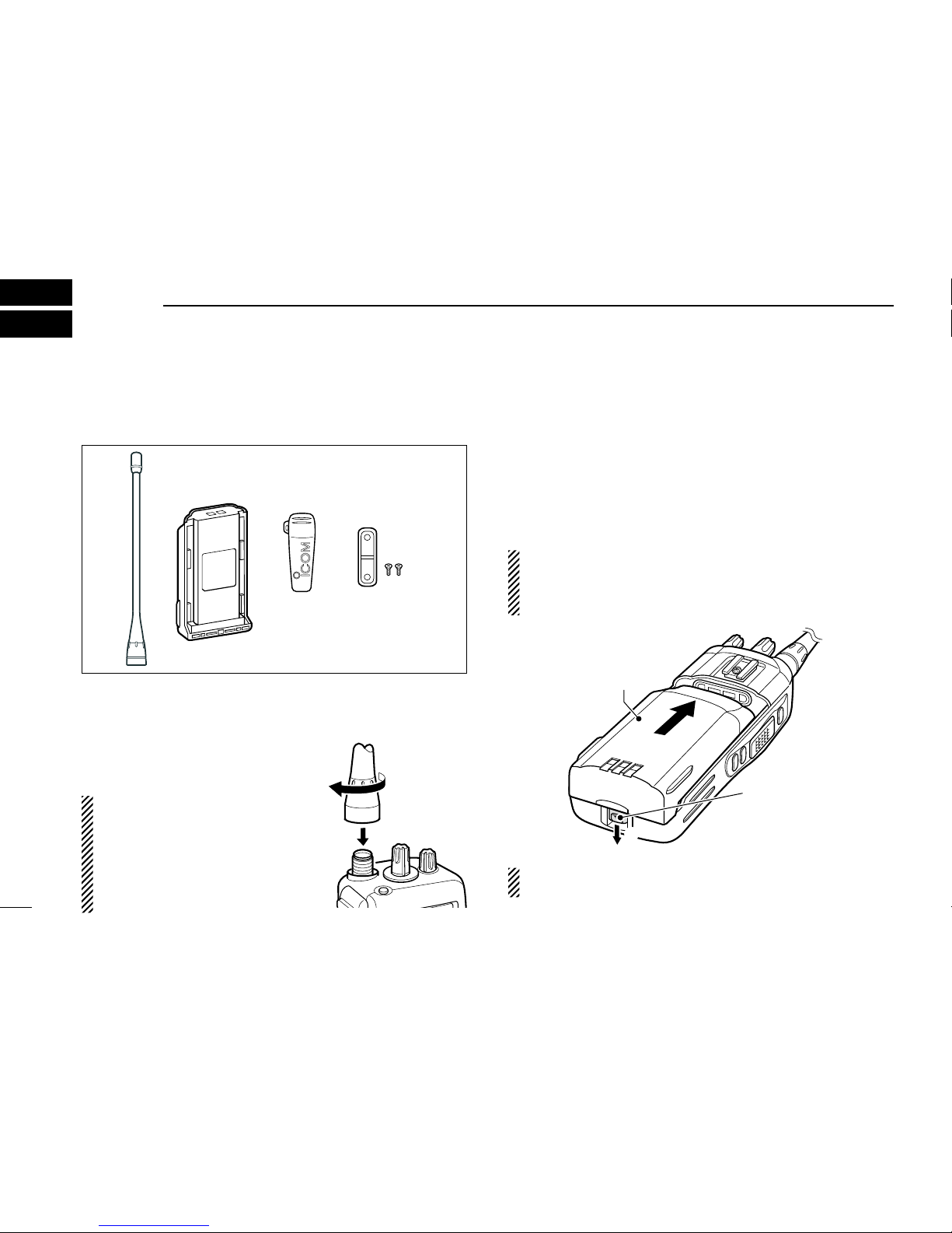
1 ACCESSORIES ...........................................................1–2
NSupplied accessories ...................................................1
NAccessory attachments ................................................ 1
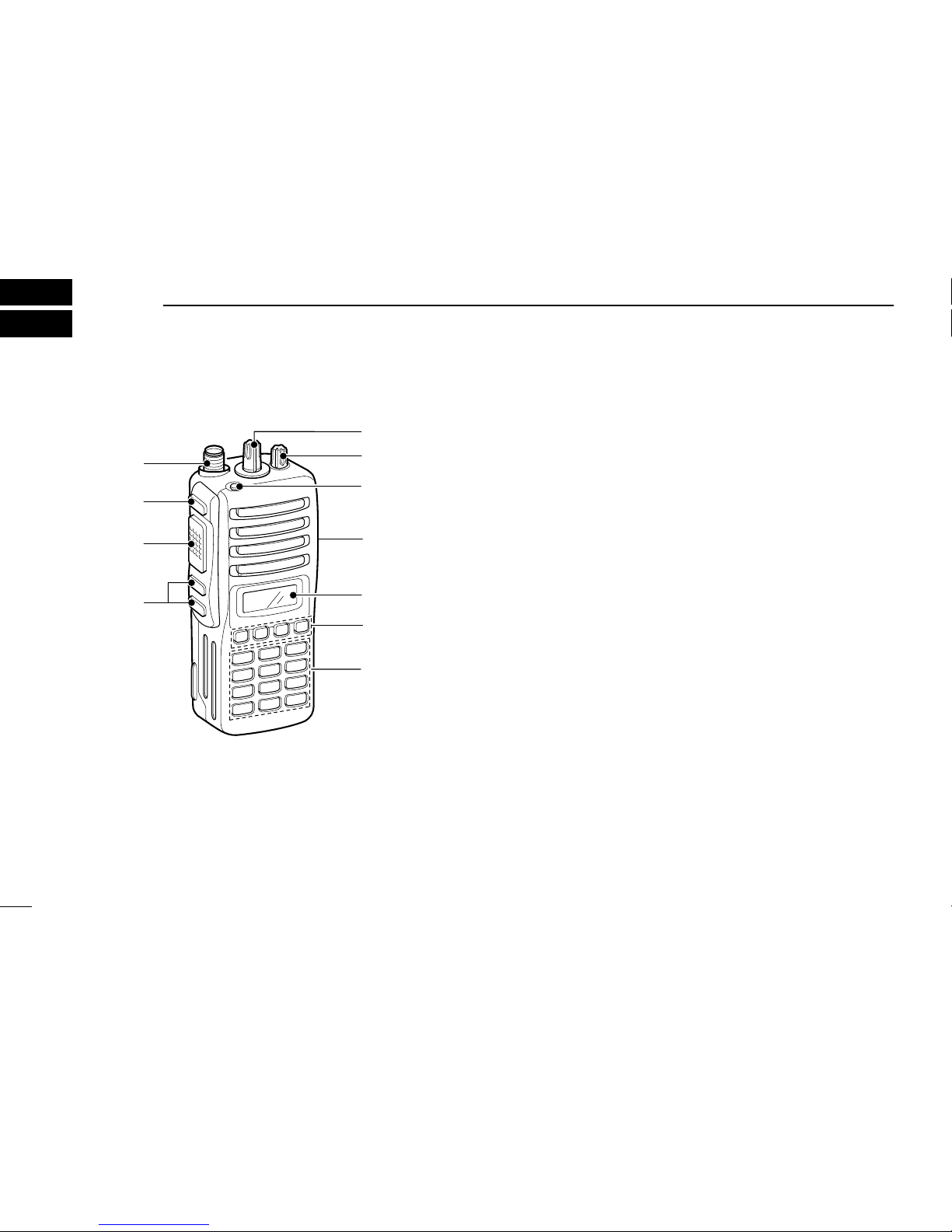
2 PANEL DESCRIPTION................................................3–7
NFront panel ...................................................................3
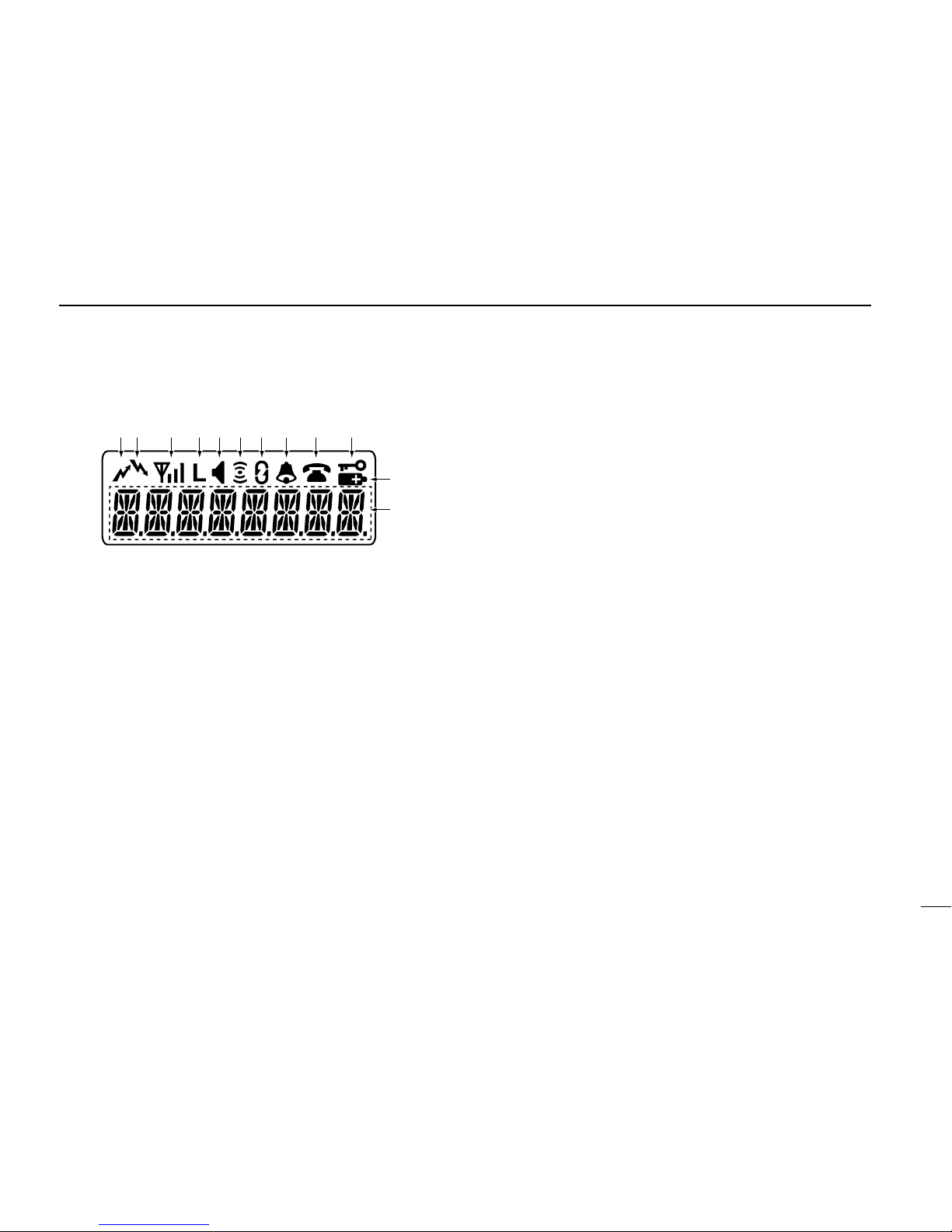
NFunction display ...........................................................4
NProgrammable function keys........................................5
3 BASIC OPERATION........................................................8
NTurning power ON ........................................................8
NChannel selection.........................................................8
NCall procedure..............................................................8
4 PASSPORT OPERATION..........................................9–11
NReceiving a call ............................................................9
NTransmitting a call.......................................................10
NOther functions...........................................................11
5 LTR OPERATION ....................................................12–13
NReceiving a call ..........................................................12
NTransmitting a call.......................................................13
6 CONVENTIONAL OPERATION ..............................14–16
NReceiving and transmitting.........................................14
NUser set mode............................................................15
NEmergency transmission............................................16
NScrambler function .....................................................16
NStun function ..............................................................16
NMan Down transmission.............................................16
7 OPTIONAL UNIT INSTALLATION ..........................17–18
NUT-124 installation......................................................17
NUT-108 installation......................................................17
N
UT-109 and UT-110 installation ....................................18
8 BATTERY CHARGING ............................................19–23
NCaution.......................................................................19
NOptional battery chargers...........................................21
9 BATTERY CASE............................................................24
NOptional battery case (BP-240)..................................24
10 SWIVEL BELT CLIP ................................................25–26
NMB-93 contents ..........................................................25
NTo attach.....................................................................25
NTo detach....................................................................26
11 OPTIONS.................................................................27–28
12 SAFETY TRAINING INFORMATION.......................29–30

1
1ACCESSORIES
NSupplied accessories
The following accessories are supplied:
Flexible antenna
Battery pack
Belt clip Jack cover
(with screws)
NAccessory attachments
DFlexible antenna
Connect the supplied flexible an-
tenna to the antenna connector.
CAUTION:
sNEVER carry the transceiver
by holding only the antenna.
sDO NOT connect the antenna
other than listed on page 28.
sTransmitting without an antenna
may damage the transceiver.
DBattery pack
To attach the battery pack:
Slide the battery pack in the direction of the arrow (q), then
lock it with the battery release button.
s3LIDE THE BATTERY PACK UNTIL THE BATTERY RELEASE BUTTON MAKES A@CLICK
sound.
To remove the battery pack:
Push the battery release button in the direction of the arrow
(w) as shown below. The battery pack is then removed.
NEVER remove or attach the battery pack when the trans-
ceiver is wet or soiled. This may result water or dust getting
into the transceiver/battery pack and may result in the
transceiver being damaged.
q
w
Battery pack
Battery release
button
NOTE: +EEP THE BATTERY PACK TERMINALS CLEAN )TS A GOOD
idea to occasionally clean them.

2
1
ACCESSORIES
DBelt clip
To attach the belt clip:
qRemove the battery pack if it is attached.
wSlide the belt clip in the direction of the arrow until the belt
CLIP IS LOCKED AND MAKES A @CLICK SOUND
To detach the belt clip:
qRemove the battery pack if it is attached.
wLift the clip (q), and slide the belt clip in the direction of
the arrow (w).
DJack cover
Attach the jack cover when the optional speaker-microphone
is not used.
q
w
To attach the jack cover:
qAttach the jack cover on
the [SP MIC] connector.
wTighten the screws.
To detach the jack cover:
qRemove the screw with a
Phillips screwdriver.
wDetach the jack cover for
the speaker-microphone
connection.
q
w
q
w

3
2PANEL DESCRIPTION
NFront panel
qROTARY SELECTOR
Selects the pre-programmed system channels or talk
groups (Max. 16) on the LTR/Passport system.
(Depending on the pre-setting)
wVOLUME CONTROL [VOL]
Turns power ON and adjusts the audio level.
eEMERGENCY KEY
Push to transmit the DTMF emergency call.
r[SP]/[MIC] JACK
Connect the optional speaker-microphone.
s !TTACH THE JACK COVER WHEN THE OPTIONAL SPEAKERMICROPHONE IS
not used. (p. 2)
tFUNCTION DISPLAY
Displays a variety of information such as operating chan-
nel name, DTMF encode channel, selected function, etc.
yDEALER-PROGRAMMABLE KEYS [P0] to [P3]
Desired functions can be programmed independently by
your dealer.
u10-KEYPAD (Depending on version)
Used to enter DTMF encode channel, phone number, etc.
iUP/DOWN [∫]/[√] KEYS
±Push to select the operating channel.
±Push to select the talk group on the LTR or Passport
system. (p. 9)
oPTT SWITCH [PTT]
Push and hold to transmit; release to receive.
!0 MONITOR KEY
Push to mute and release the CTCSS (DTCS) squelch
mute. Open squelch/deactivate mute while pushing this
key.
!1 ANTENNA CONNECTOR
Connects the supplied antenna.
it
r
q
e
u
y
w
o
!0
!1
10-keypad version

4
2
PANEL DESCRIPTION
NFunction display
qTRANSMIT INDICATOR
Appears while transmitting.
wBUSY INDICATOR
Appears while the channel is busy.
eSIGNAL STRENGTH INDICATOR
±Indicates relative signal strength level.
±Does not appear when the transceiver is out of the
communication area on the PassPort system.
rLOW POWER INDICATOR
Appears when low output power is selected.
s7HEN THE BATTERY POWER DECREASES TO ASPECIFIED LEVEL LOW
power is selected automatically.
tMONITOR INDICATOR
Appears when the monitor key is pushed.
yCOMPANDER INDICATOR
Appears when the compander function is activated.
uSCRAMBLER INDICATOR
Appears when the voice scrambler function is activated.
iBELL INDICATOR
±Appears when the DTMF select call function is acti-
vated.
±Blinks when the DTMF select call is received.
oPHONE INDICATOR
±Appears on the system channel/talk group in which a
phone call is available.
±Blinks when the phone call is received.
!0 KEY LOCK INDICATOR
Appears during the key lock function ON.
!1 BATTERY INDICATOR
Appears or blinks when the battery power decreases to a
specified level.
!2 ALPHANUMERIC DISPLAY
Displays an operating channel name, DTMF encode
channel, etc.
q!0oiuytrew
!1
!2

5
2PANEL DESCRIPTION
NProgrammable function keys
The following functions can be assigned to [P0], [P1], [P2],
[P3], [Emergency], [Monitor], [M]* and [#]* programmable
function keys.
Consult your Icom dealer or system operator for details con-
cerning your transceivers programming.
If the programmable function names are bracketed in the
following explanations, the specific key used to activate the
function depends on programming.
*Available on 10-keypad version only.
SEND DTMF KEY
Push to enter the DTMF encode channel selection mode.
SELECT CALL KEY
±Push to turn the DTMF select call mute function ON.
±Push and hold to turn the DTMF select call mute function
OFF.
PRIORITY KEY
Push to select the priority channel.
EMERGENCY KEY
Push to select the priority channel and automatically trans-
mit a DTMF emergency call code.
SCAN A KEY
±4HIS KEYS OPERATION DEPENDS ON THE 0OWER /. 3CAN SET-
ting.
When the power ON scan function is turned OFF;
Push to start and cancel scanning operation. In case of
transmission during scan, cancels scanning.
When the power ON scan function is turned ON;
Push to pause scanning. Scanning resumes after pass-
ing a specified time period. In case of transmission during
scan, pauses scanning. Scanning resumes after passing
a specified time period specified.
±Push and hold this key for 1 sec. to indicate the scan
group, then push to select the desired group.
SCAN B KEY
±Push to start and cancel scanning operation. In case of
transmission during scan, pauses scanning. Scanning
resumes after passing a specified time period.
±Push and hold this key for 1 sec. to indicate the scan
group, then push to select the desired group.
PRIORITY CHANNEL KEYS
±Push to select Priority A or Priority B channel.
±Push and hold [Prio A (Rewrite)] to rewrite the Prio A
channel.

6
2
PANEL DESCRIPTION
MONITOR KEY
Push to mute and release the CTCSS (DTCS) squelch mute.
Open squelch/deactivate mute while pushing this key.
NUISANCE DELETE KEY
Push to cancel the displayed channel from the scan list in
the talk group.
SCAN TYPE KEY
Push to toggle the scan type from Individual or Block.
SPEED DIAL KEY
Push to send the most recently transmitted DTMF code se-
lected with [Send DTMF].
TALK AROUND KEY
Turn the talk around function ON and OFF.
This function equalizes the transmit frequency to the receive
frequency for transceiver-to-transceiver communication.
WIDE/NARROW KEY
0USH TO TOGGLE THE )& PASSBAND WIDTH FROM h7IDEv OR h.AR-
ROWv CHANNEL SPACING FOR BOTH TRANSMISSION AND RECEPTION
temporarily. Once the channel or bank has changed, the
passband width returns to the original setting.
TX POWER KEY
Push to toggle the transmit output power level from the inde-
pendent settings of each channel.
RE-DIAL KEY
Push to send the most recently transmitted DTMF code ed-
ited with 10-keypad.
RSSI KEY
Push to display the RSSI (Received Signal Strength Indica-
tor) level.
MODE DISPLAY TYPE KEY
Push to toggle the scan mode display type from Individual
and Block.
LOCK KEY
Push and hold for 2 sec. to turn the lock function ON and
OFF.
PHONE REQUEST KEY
Push to turn the phone call function ON and OFF in the op-
erating channel.

7
2PANEL DESCRIPTION
ROAM REQUEST KEY
±Push to return to the home site.
±Push and hold to start roaming.
SITE LOCK KEY
Push to turn the Site Lock function ON and OFF.
This function inhibits automatic roaming, and can be useful
when the transceiver is out of the communication area such
as on a subway or in an elevator.
EMERGENCY KEY
Push and hold for the specified time period to select the
emergency channel and automatically send a DTMF emer-
gency signal once or repeatedly.
SCRAMBLER KEY
Push to toggle the scrambler function ON or OFF.
COMPANDER KEY
Push to turn the compander function ON and OFF.
The compander function reduces noise components from
the transmitted audio to provide clear communication.
USER SET MODE KEY
Push for 1 sec. to enter the User set mode.
The User set mode allows you to set seldom-changed set-
tings.
Push this key momentarily in the User set mode to select
the function, and push [CH Up] or [CH Down] to change the
setting.
SIREN KEY
Push to emit a siren. This function can be used for situations
such as a security alarm for example.
SELECT MODE KEY (available for Passport/LTR only)
Push to select the operating mode from System or Talk
Group.
s 3YSTEM CHANNEL AND TALK GROUP SELECTION
qPush [Select Mode] to select the operating mode from
System or Talk Group.
wThen push [UP] or [DOWN] to select the desired system
channel or talk group, in sequence.

8
3
BASIC OPERATION
NTurning power ON
qRotate [VOL] to turn the power ON.
wIf the transceiver is programmed for a start up passcode,
input the digit codes as directed by your dealer.
s 4HE KEYS IN THE TABLE BELOW CAN BE USED FOR PASSWORD INPUT
s 4HE TRANSCEIVER DETECTS NUMBERS IN THE SAME BLOCK AS IDENTICAL
4HEREFORE hv AND hv ARE THE SAME
e7HEN THE h0!337/2$v INDICATION DOES NOT CLEAR AFTER IN-
putting 4 digits, the input code number may be incorrect.
Turn the power off and start over in this case.
NChannel selection
Push [UP] or [DOWN], or rotate [ROTARY SELECTOR]
to select the desired system channel or talk group, in se-
quence.
s 5P TO PREPROGRAMMED CHANNELS CAN BE SELECTED VIA [ROTARY
SELECTOR].
NCall procedure
7HEN YOUR SYSTEM EMPLOYS TONE SIGNALLING EXCLUDING
CTCSS and DTCS), the call procedure may be necessary
prior to voice transmission. The tone signalling employed may
be a selective calling system which allows you to call specific
station(s) only and prevent unwanted stations from contact-
ing you.
qSelect the desired DTMF encode channel according to
YOUR 3YSTEM /PERATORS INSTRUCTIONS
s 4HIS MAY NOT BE NECESSARY DEPENDING ON PROGRAMMING
s 2EFER TO PAGES OR FOR SELECTION
wPush the [PTT].
eAfter transmitting a DTMF code, the remainder of your
communication can be carried out in the normal fashion.
Selective calling Non-selective calling
KEY
NUMBER 0
5
4
9
3
8
2
7
1
6
UP

9
4PASSPORT OPERATION
NReceiving a call
DGroup call
qPush [UP] or [DOWN], or rotate [ROTARY SELECTOR]
to select the Passport system channel or talk group.
w7HEN A CALL IS RECEIVED
s h v AND THE CALLING STATION NAME)$ APPEAR
ePush and hold [PTT], then speak into the microphone at
a normal voice level.
rRelease [PTT] to return to receive.
DIndividual call
qPush [UP] or [DOWN], or rotate [ROTARY SELECTOR]
to select the Passport system channel or talk group.
w7HEN A CALL IS RECEIVED
s h v AND THE CALLING STATION NAME)$ APPEAR
ePush and hold [PTT], then speak into the microphone at
a normal voice level.
rRelease [PTT] to return to receive.
tTo finish the conversation, push [DOWN] to send the
h#LEAR $OWNv SIGNAL
DSelective call (DTMF call)
—Optional UT-108 is required—
qPush [UP] or [DOWN], or rotate [ROTARY SELECTOR]
to select the Passport system channel or talk group.
wPush [Select call] to mute the channel.
s h v APPEARS
Appears
e7HEN RECEIVING ACALL THE CALLING STATION NAME APPEARS
and a beep is emitted. Then the mute is released.
s h v DISAPPEARS
DPhone call
qPush [UP] or [DOWN], or rotate [ROTARY SELECTOR]
to select the Passport system channel or talk group.
w7HEN APHONE CALL IS RECEIVED TRANSCEIVER RINGS PUSH
and hold [PTT], then speak into the microphone at a nor-
mal voice level.
s h v BLINKS AND CALLING STATION NAME)$ APPEARS FOR SEC
Blinks
eRelease [PTT] to return to receive.
rPush [#] while pushing [PTT] to finish the communication.

10
4
PASSPORT OPERATION
NTransmitting a call
DGroup call
qPush [UP] or [DOWN], or rotate [ROTARY SELECTOR]
to select the Passport system channel or talk group in
which the group ID is pre-programmed.
w7HILE PUSHING AND HOLDING [PTT], speak into the micro-
phone at a normal voice level after a beep is emitted.
s )F AN ERROR BEEP IS EMITTED RELEASE [PTT]. After a while, repeat
step wagain.
s 4HE BEEP CAN BE TURNED /&& IN 5SER SET MODE
s7HEN THE TRANSCEIVER IS OUT OF THE COMMUNICATION AREA h v
DISAPPEARS AND h./ 36#v MESSAGE APPEARS
DIndividual call
qPush [UP] or [DOWN], or rotate [ROTARY SELECTOR]
to select the Passport system channel or talk group in
which the MID (Mobile ID) is pre-programmed.
w7HILE PUSHING AND HOLDING [PTT], speak into the micro-
phone at a normal voice level after a beep is emitted.
s )F AN ERROR BEEP IS EMITTED RELEASE [PTT]. After a while, repeat
step wagain.
s 4HE BEEP CAN BE TURNED /&& IN 5SER SET MODE
s7HEN THE TRANSCEIVER IS OUT OF THE COMMUNICATION AREA h v
DISAPPEARS AND h./ 36#v MESSAGE APPEARS
eTo finish the conversation, push [DOWN] to send the
h#LEAR $OWNv SIGNAL
DSelective call (DTMF call)
—Optional UT-108 is required—
qPush [UP] or [DOWN], or rotate [ROTARY SELECTOR]
to select the Passport system channel or talk group.
wPush [Send DTMF]— a DTMF encode channel appears.
ePush [UP] or [DOWN] to select the desired DTMF en-
code channel.
rPush [PTT] to transmit the selected DTMF code in the
selected DTMF channel.
s 0USH [P0] to cancel the DTMF transmission.
DPhone call (Available for 10-keypad version only)
qPush [UP] or [DOWN], or rotate [ROTARY SELECTOR]
to select the Passport system channel or talk group.
wPush [Phone request] to enable the phone call.
s h v APPEARS
Appears
ePush [PTT] to connect the phone line.
s 4HE PROCEED TONE IS EMITTED AFTER CONNECTION TO THE PHONE LINE
r
7HILE PUSHING AND HOLDING [PTT], enter the phone number
via the 10-keypad to make the call. Then release [PTT].
tPush [PTT] to transmit; release to receive.
yPush [#] while pushing [PTT] to finish the communication.

11
4PASSPORT OPERATION
NOther functions
DManual roaming start function
If the transceiver has [Roam Request] assigned to it, you
can start roaming manually to search for another site.
qPush [UP] or [DOWN], or rotate [ROTARY SELECTOR]
to select the Passport system channel or talk group.
wPush and hold [Roam Request] to start roaming.
s h2/!-3)4%v IS DISPLAYED
s 7HEN h).6!,)$v IS DISPLAYED THE HOME REPEATER MAY NOT HAVE
a neighbour site. After a while, repeat step w.
ePush [Roam Request] to cancel roaming.
DSite lock function
If the transceiver has [Site Lock] assigned to it, automatic
roaming can be inhibited. This function is useful when the
transceiver is out of the communication area such as on a
subway or in an elevator.
qPush [UP] or [DOWN], or rotate [ROTARY SELECTOR]
to select the Passport system channel or talk group.
wPush [Site Lock] to turn the site lock function ON and
OFF.
s h3)4%,/#+v IS DISPLAYED

12
5
LTR OPERATION
NReceiving a call
DGroup call
qPush [UP] or [DOWN], or rotate [ROTARY SELECTOR]
to select the LTR system channel or talk group.
w7HEN A CALL IS RECEIVED
s h v AND THE CALLING STATION NAME)$ APPEAR
ePush and hold [PTT], then speak into the microphone at
a normal voice level.
rRelease [PTT] to return to receive.
DSelective call (DTMF call)
—Optional UT-108 is required—
qPush [UP] or [DOWN], or rotate [ROTARY SELECTOR]
to select the LTR system channel or talk group.
wPush [Select call] to mute the channel.
s h v APPEARS
Appears
e7HEN RECEIVING ACALL THE CALLING STATION NAME APPEARS
and a beep is emitted. Then the mute is released.
s h v DISAPPEARS
DPhone call
qPush [UP] or [DOWN], or rotate [ROTARY SELECTOR]
to select the LTR system channel or talk group.
w7HEN APHONE CALL IS RECEIVED TRANSCEIVER RINGS PUSH
and hold [PTT], then speak into the microphone at a
normal voice level.
s h v BLINKS AND CALLING STATION NAME)$ APPEARS FOR SEC
Blinks
eRelease [PTT] to return to receive.
rPush [#] while pushing [PTT] to finish the communication.

13
5LTR OPERATION
NTransmitting a call
DGroup call
qPush [UP] or [DOWN], or rotate [ROTARY SELECTOR]
to select the LTR system channel or talk group.
w7HILE PUSHING AND HOLDING [PTT], speak into the micro-
phone at a normal voice level after a beep is emitted.
s )F AN ERROR BEEP IS EMITTED RELEASE [PTT]. After a while, repeat
step w.
s 4HE BEEP CAN BE TURNED /&& IN 5SER SET MODE
DSelective call (DTMF call)
—Optional UT-108 is required—
qPush [UP] or [DOWN], or rotate [ROTARY SELECTOR]
to select the LTR system channel or talk group.
wPush [Send DTMF]— a DTMF encode channel appears.
ePush [UP] or [DOWN] to select the desired DTMF en-
code channel.
rPush [PTT] to transmit the selected DTMF code in the
selected DTMF channel.
s 0USH [Send DTMF] to cancel the DTMF transmission.

14
6
CONVENTIONAL OPERATION
NReceiving and transmitting
NOTE: Transmitting without an antenna may damage the
transceiver. See page 1 for antenna attachment.
Receiving:
qRotate [VOL] to turn the power ON.
wPush [UP] or [DOWN], or rotate [ROTARY SELECTOR]
to select the conventional system channel, in sequence.
e7HEN RECEIVING ACALL ADJUST THE AUDIO OUTPUT LEVEL TO A
comfortable listening level.
Transmitting:
7AIT FOR THE CHANNEL TO BECOME CLEAR TO AVOID INTERFERENCE
q7HILE PUSHING AND HOLDING [PTT], speak into the micro-
phone at a normal voice level.
wRelease [PTT] to return to receive.
IMPORTANT: To maximize the readability of your signal;
1. Pause briefly after pushing [PTT].
2. Hold the microphone 5 to 10 cm (2 to 4 inches) from
your mouth, then speak into the microphone at a nor-
mal voice level.
DTransmitting notes
s 4RANSMIT INHIBIT FUNCTION
The transceiver has several inhibit functions which restrict
transmission under the following conditions:
- Channel is busy.
- Un-matched (or matched) CTCSS is received.
4HE SELECTED CHANNEL IS A @RECEIVE ONLY CHANNEL
s 4IMEOUT TIMER
After continuous transmission for the pre-programmed time
period, the time-out timer is activated, causing the trans-
ceiver to stop transmitting.
s 0ENALTY TIMER
Once the time-out timer is activated, transmission is further
inhibited for a period determined by the penalty timer.

15
6#/.6%.4)/.!, /0%2!4)/.
DDTMF receiving and transmitting
—Optional UT-108 is required—
If the transceiver has [Send DTMF] assigned to it, a
DTMF encode channel is displayed when pushed, and as-
signed DTMF encode channels can be selected via [UP] or
[DOWN].
Receiving:
qPush [UP] or [DOWN], or rotate [ROTARY SELECTOR]
to select the conventional system channel, in sequence.
wPush [Select call] to mute the channel. (“ v APPEARS
e7HEN RECEIVING ACALL ABEEP IS EMITTED AND MUTE IS RE-
leased. (“ v DISAPPEARS
Transmitting:
qPush [UP] or [DOWN], or rotate [ROTARY SELECTOR]
to select the conventional system channel, in sequence.
wPush [Send DTMF]— a DTMF encode channel appears.
ePush [UP] or [DOWN] to select the desired DTMF en-
code channel.
rPush [PTT] to transmit the selected DTMF code in the
selected DTMF channel.
s 0USH [P0] to cancel the DTMF transmission.
NUser set mode
If the transceiver has [User Set Mode] assigned to it, you
CAN hCUSTOMIZEv THE TRANSCEIVER OPERATION TO SUIT YOUR PREFER-
ences and operating style.
Entering the user set mode:
qPush and hold [User Set Mode] to enter user set mode.
Push [User Set Mode] momentarily to select the item.
Then push [UP] or [DOWN] to set the desired level/condi-
tion.
Available set mode functions:
s "ACKLIGHT /. !UTO OR /&&
s 2INGER /. OR /&&
s "EEP /. OR /&&
s 31, ,EVEL TO
s -IC 'AIN TO
s "ATTERY 6OLTAGE /. OR /&&
s 3YSTEM )NFORMATION /. OR /&&
s 2UN4IME 4HE TRANSCEIVERS RUNNING TIME IS
displayed.
wPush and hold [User Set Mode] to exit user set mode.
Other manuals for IC-F43TR
3
Table of contents
Other Icom Radio manuals

Icom
Icom IC-F3001 Installation and operating instructions

Icom
Icom IC-F5061 Building instructions

Icom
Icom Two-Way Radios Instruction Manual

Icom
Icom IC-F4TR User manual

Icom
Icom IC-4008A User manual

Icom
Icom IC-F1020 User manual

Icom
Icom IC-F3160 SERIES Manual

Icom
Icom V10MR Operating instructions

Icom
Icom IC-R71A User manual

Icom
Icom IC-F40GT User manual
Popular Radio manuals by other brands

Albrecht
Albrecht DR 790 CD manual

Sunwave
Sunwave CrossFire M2 Commissioning Guide

Philips
Philips AE3805 user manual

Coby
Coby CX 96 - Personal Radio Operation manual

Harbor Freight Tools
Harbor Freight Tools AM/FM 94670 Assembly & operating instructions

Nokia Siemens Networks
Nokia Siemens Networks SRAL XD SERIES user manual