Icom id- rp2 User manual

D-STAR REPEATER SYSTEM
id- rp2
Instruction Manual

IMPORTANT
READ THIS INSTRUCTION MANUAL
CAREFULLY before attempting to operate the re-
peater.
SAVE THIS INSTRUCTION MANUAL. This
manual contains important safety and operating in-
structions for the ID-RP2 system.
EXPLICIT DEFINITIONS
WORD DEFINITION
RWARNING Personal injury, fire hazard or electric
shock may occur.
CAUTION Equipment damage may occur.
NOTE
If disregarded, inconvenience only. No
risk or personal injury, fire or electric
shock.
PRECAUTIONS
RDANGER! ID-RP2 installation, particularly ID-
RP2L and antennas, is intended for professional in-
stallation only. We are not responsible for any building
breakage, any damage resulting from a drop of the ID-
RP2L or antenna from a high place or unstable site or
resulting from any personal injury nor any accident in
any other cases. Be sure to consult an expert engineer
for installations.
RWARNING RF EXPOSURE! This device emits
Radio Frequency (RF) energy. Extreme caution should
be observed when operating this device. If you have
any questions regarding RF exposure and safety stan-
dards please refer to the Federal Communications
Commission Office of Engineering and Technology’s
report on Evaluating Compliance with FCC Guidelines
for Human Radio Frequency Electromagnetic Fields
(OET Bulletin 65).
RWARNING HIGH VOLTAGE! NEVER attach an
antenna or internal antenna connector during trans-
mission. This may result in an electrical shock or burn.
RWARNING HIGH VOLTAGE! NEVER install the
antenna at any place that person touch the antenna
easily during transmission. This may result in an elec-
trical shock or burn.
RNEVER apply AC to the [DC 13.8V IN] connector.
This could cause a fire or ruin the repeater.
RNEVER apply more than 16 V DC, such as a 24 V
battery, to the [DC 13.8V IN] connector on the re-
peater. This could cause a fire or ruin the repeater.
RNEVER let metal, wire or other objects touch any
internal part or connectors on the repeater. This may
result in an electric shock.
RNEVER operate or touch the repeater unit, ID-
RP2C, ID-RP2D and ID-RP2V, with wet hands. This
may result in an electric shock or damage to the re-
peater unit.
RNEVER expose the repeater unit, ID-RP2C, ID-
RP2D and ID-RP2V, to rain, snow or any liquids.
These units have no water protection.
AVOID using or placing the repeater unit, ID-RP2C,
ID-RP2D and ID-RP2V, in areas with temperatures
below –10°C (+14°F) or above +50°C (+122°F). Be
aware that temperatures can exceed 80°C (+176°F), re-
sulting in permanent damage to the repeater if left
there for extended periods.
AVOID using or placing the ID-RP2L in areas with tem-
peratures below –30°C (–22°F) or above +60°C
(+140°F). Be aware that temperatures on a vehicle’s
dashboard can exceed 80°C (+176°F), resulting in per-
manent damage to the repeater if left there for ex-
tended periods.
AVOID placing the repeater unit, ID-RP2C, ID-RP2D
and ID-RP2V, in excessively dusty environments or in
direct sunlight.
Place the repeater in a secure place to avoid inadver-
tent use by children.
DO NOT use chemical agents such as benzine or al-
cohol when cleaning, as they can damage the re-
peater’s surfaces.
DO NOT modify the repeater for any reason.
Use the specified fuse only.
For U.S.A. only
CAUTION: Changes or modifications to this repeater,
not expressly approved by Icom Inc., could void your
authority to operate this repeater under FCC regula-
tions.
CAUTION: The ID-RP2L is intended for use as a fixed
base station with the antenna located outdoors on the
rooftop or on antenna tower.
i

ii
Icom, Icom Inc. and the logo are registered trademarks
of Icom Incorporated (Japan) in the United States, the United
Kingdom, Germany, France, Spain, Russia and/or other
countries.
Microsoft and Windows are registered trademarks of Mi-
crosoft Corporation in the United States and/or other coun-
tries.
TABLE OF CONTENTS
IMPORTANT ....................................................................... i
EXPLICIT DEFINITIONS .................................................... i
PRECAUTIONS .................................................................. i
TABLE OF CONTENTS .................................................... ii
1 SYSTEM OUTLINE .................................................. 1– 2
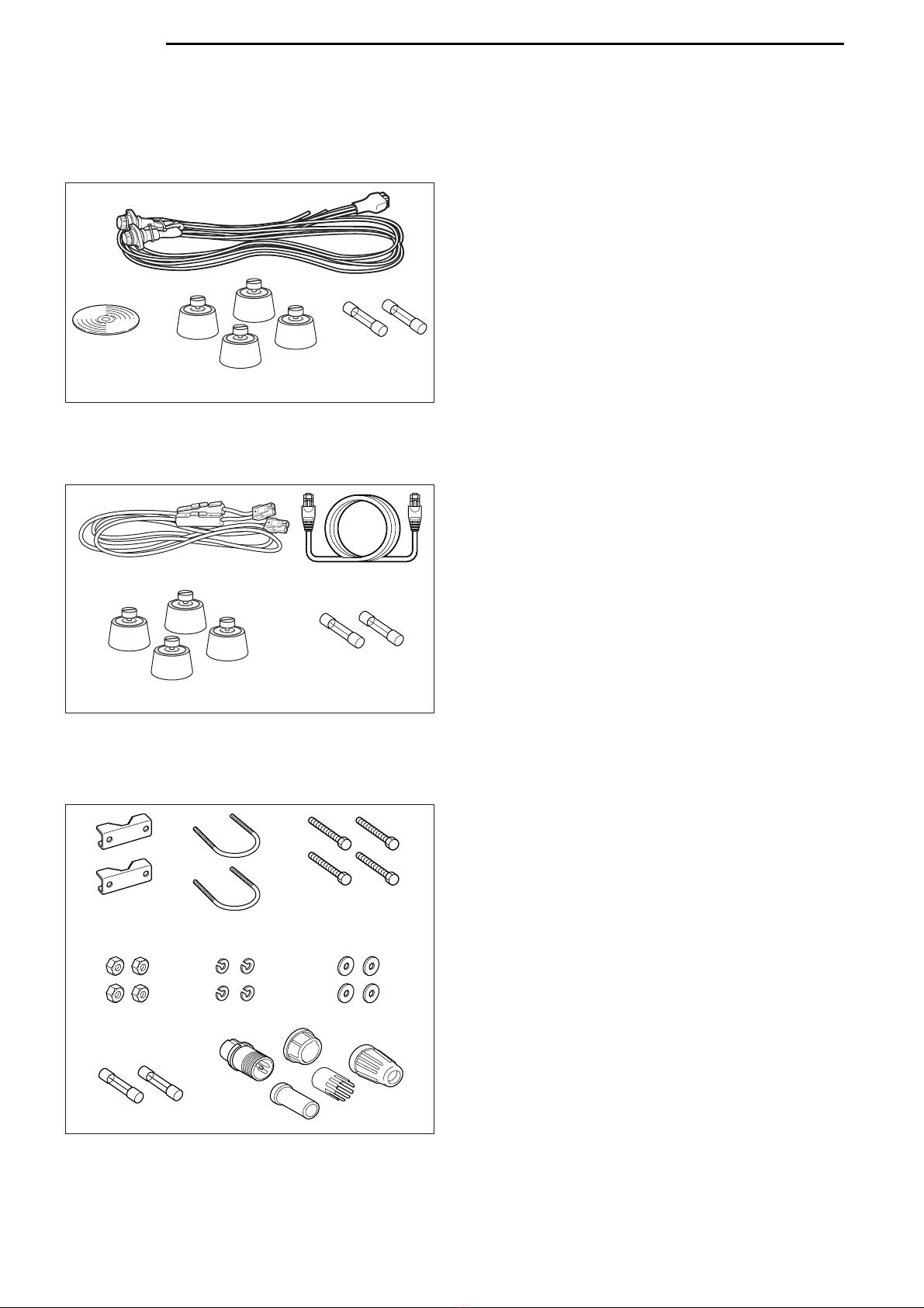
2 SUPPLIED ACCESSORIES ..................................... 3–4
■Accessories for ID-RP2C ..................................................... 3
■Accessories for ID-RP2D/ID-RP2V ...................................... 3
■Accessories for ID-RP2L ...................................................... 3
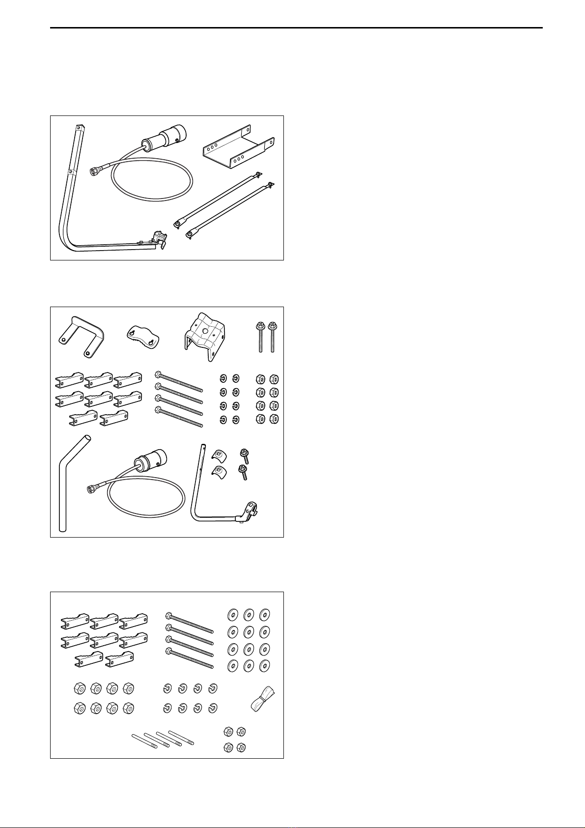
■Accessories for AH-106 ........................................................ 4
■Accessories for AH-107 ........................................................ 4
■Accessories for AH-108 ........................................................ 4
3 PANEL DESCRIPTIONS .......................................... 5–8
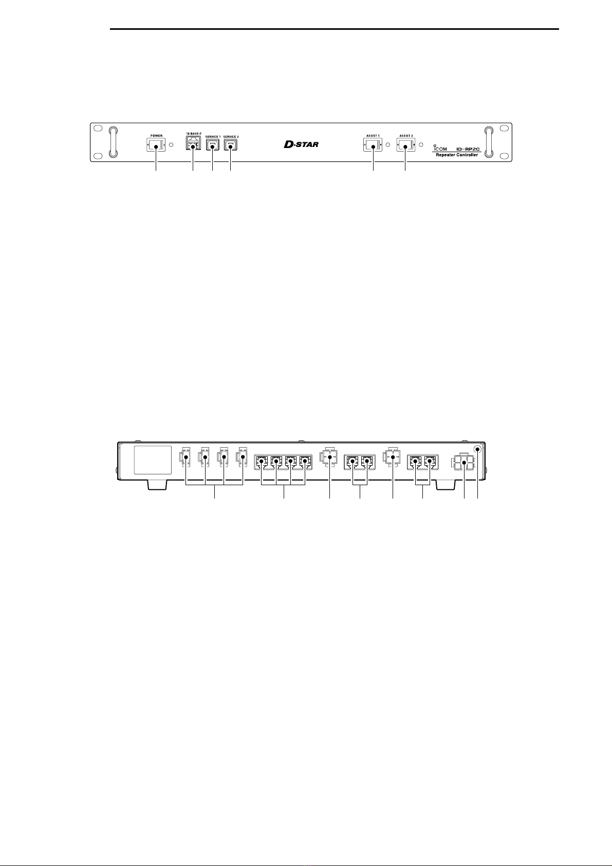
■ID-RP2C (Front panel) ......................................................... 5
■ID-RP2C (Rear panel) .......................................................... 5
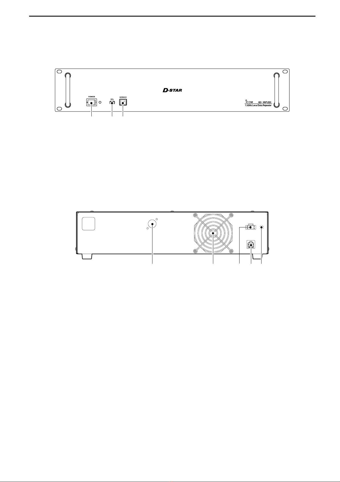
■ID-RP2D (Front panel) ......................................................... 6
■ID-RP2D (Rear panel) .......................................................... 6
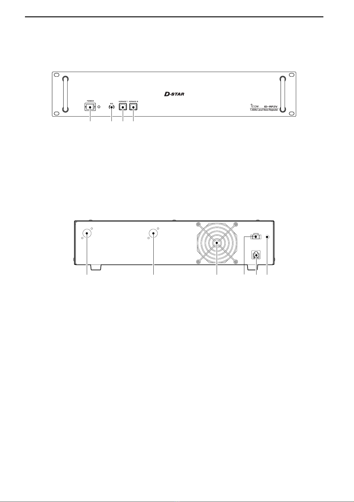
■ID-RP2V (Front panel) ......................................................... 7
■ID-RP2V (Rear panel) .......................................................... 7
■ID-RP2L ............................................................................... 8
4 CONNECTIONS AND INSTALLATIONS ............... 9–18
■Precautions .......................................................................... 9
DAbout coaxial cable .......................................................... 9
■About the power supply ........................................................ 9
■When install into system rack ............................................. 10
■Rubber feet attachment ...................................................... 10
■Grounding .......................................................................... 10
■System connections ........................................................... 11
■Antenna assembling ........................................................... 12
DAH-106 ........................................................................... 12
DAH-107 ........................................................................... 14
DAH-108 ........................................................................... 16
■ID-RP2L installation ........................................................... 17
■Adjusting the parabolic antenna ......................................... 18
DAbout the test plug ......................................................... 18
DParabolic antenna beam adjustment .............................. 18
5 DRIVER INSTALLATIONS ................................... 19–33
■Microsoft®Windows®XP (Service Pack 2) ......................... 19
■Microsoft®Windows®2000 ................................................. 24
■Microsoft®Windows®98/Me ............................................... 28
■COM port confirmation ....................................................... 31
DMicrosoft®Windows®XP/2000 ....................................... 31
DMicrosoft®Windows®98/Me ........................................... 32
■USB driver un-installation ................................................... 33
6 UTILITY INSTALLATION ..................................... 34–36
■Installation .......................................................................... 34
■Un-installation .................................................................... 36
7 REPEATER SETTINGS ....................................... 37–44
■ID-RP2C settings ............................................................... 37
DID-RP2C utility screen .................................................... 38
■Frequency setting for ID-RP2D .......................................... 41
■Frequency setting for ID-RP2V .......................................... 42
■ID-RP2L setting .................................................................. 43
8 MAINTENANCE ................................................... 45–46
■Troubleshooting .................................................................. 45
■About cleaning .................................................................... 46
■Fuse replacement .............................................................. 46
DOPC-1309 ...................................................................... 46
DOPC-1380 ...................................................................... 46
DID-RP2L’s DC power cable ............................................ 46
9 SPECIFICATIONS AND OPTIONS ...................... 47–48
■Specifications ..................................................................... 47
DID-RP2C ......................................................................... 47
DID-RP2L ......................................................................... 47
DID-RP2D/ID-RP2V .......................................................... 48
■Options ............................................................................... 48

1SYSTEM OUTLINE
1
The D-star repeater site can be constructed by com-
bining with the following units according to the plan or
scale.
ID-RP2C : Repeater controller
ID-RP2D : 1.2 GHz data repeater
ID-RP2V : 1.2 GHz digital voice repeater
ID-RP2L : 10 GHz microwave link repeater
In addition, the following options are also required for
system repeater operations.
AH-106 : 10 GHz Parabolic antenna 800 (d)
AH-107 : 10 GHz Parabolic antenna 450 (d)
AH-108 : 1.2 GHz Collinear antenna
■ID-RP2C
➥The ID-RP2C is a repeater controller and one con-
troller should be used in each repeater site.
The controller relays digital voice or data (traffic) sig-
nals for repeater operation.
➥Total 4 interface connectors for local repeater con-
nections are available.
Both digital voice and data repeaters can be con-
nected as desired.
• Standard composition:
Data repeater 1
Digital voice repeater 1
Spares 2 (for another band’s repeater)
NOTE: Connect only 1 or 2 repeaters for the
same frequency band is recommended
to avoid interference.
➥Total 2 interface connectors for microwave link re-
peater connections are available.
Microwave link repeater can be connected as de-
sired.
➥One Ethernet port (10Base-T) is available for re-
peater site call sign, IP address settings etc., from
the PC and the ID-RP2C utility software.
Or, a gateway control PC can be connected as de-
sired.
➥By connecting the ID-RP2L utility installed PC, op-
erating frequency set and operation monitor can be
made.
■ID-RP2D
➥ID-RP2D is a 1.2 GHz data (128 kbps) repeater and
connects to the ID-RP2C.
*The ID-RP2D never functions as a repeater without ID-
RP2C, due to no relay function is built-in.
➥The ID-RP2D/V utility software, supplied with the ID-
RP2C, and a PC are required for both receive and
transmit frequency settings.
➥Repeater operation is performed in simplex mode on
the same frequency for data mode, however, differ-
ent frequencies between transmit and receive can
be set in simplex mode.
■ID-RP2V
➥ID-RP2V is a 1.2 GHz digital voice and slow-speed
data repeater (4.8 kbps) and connects to the ID-
RP2C.
*The ID-RP2V never functions as a repeater without ID-
RP2C, due to no relay function is built-in.
NOTE: No audio CODEC is performed in the ID-
RP2V, thus the ID-RP2V receives and
transmits 4.8 kbps serial data only.
➥Different frequencies are used for each transmission
and reception in semi-duplex mode.
➥The ID-RP2D/V utility software, supplied with the ID-
RP2C, and a PC are required for both receive and
transmit frequency settings.
■ID-RP2L
➥ID-RP2L is a 10 GHz microwave link repeater (10
Mbps) and connects to the ID-RP2C. The microwave
link repeater provides to linking with another re-
peater site (Area) for zone construction.
➥Different frequencies are used for each transmission
and reception in full-duplex mode and the reversed
frequencies between transmit and receive are used
for the oncoming repeater.
➥The received GMSK serial bit-stream signal (10
Mbps) is applied to either ID-RP2D or ID-RP2V via
the ID-RP2C. Then the GMSK serial data is trans-
mitted to the local station.
➥The ID-RP2L has a duplexer, and the condition of
the microwave link repeater can be monitored when
the ID-RP2L utility software (supplied with the ID-
RP2C) installed PC is connected to the ID-RP2C.

2
1
SYSTEM OUTLINE
DDAH-106 : 10 GHz parabolic antenna 800 (d)
DDAH-107 : 10 GHz parabolic antenna 450 (d)
➥Both AH-106 and AH-107 are offset parabolic an-
tenna and connect to ID-RP2L.
Up to 20 km (approx.; 12.4 miles)* or 8 km (approx.;
5 miles)* of communication range is provided when
AH-106 or AH-107 is used at the both microwave
link repeaters, respectively.
And up to 12 km (approx.; 7.5 miles)* of communica-
tion range is provided between AH-107 and AH-
106’s repeaters.
*Communication range may differ/change according to en-
vironment, such as weather, installed conditions, etc.
DDAH-108 : 1.2 GHz Collinear antenna
➥2 Collinear antennas are built-in and better isolation
is provided than separated 2 antennas.
Zone
Area
Signal
Internet
Antenna ID-RP2L
D-
ST
AR
POWER
10 BESE-T
SERVICE 1SERVICE 2
ASSIST 1ASSIST 2
ID-RP2C
RepeaterController
D-
ST
AR
SERVICE
POWER
ID-RP2D
RepeaterController
L/H
D-
ST
AR
SERVICE TSERVICE R
POWER
ID-RP2V
RepeaterController
ID-RP2C
ID-RP2V ID-RP2D
InternetInternet

2
3
SUPPLIED ACCESSORIES
■Accessories for ID-RP2C
qPower cable (OPC-1380; approx. 3 m; 10 ft) ……… 1
wUtility CD …………………………………………… 1
eRubber feet ………………………………………… 4
rSpare fuses (FGB01 30A) ………………………… 2
■Accessories for ID-RP2D/ID-RP2V
qPower cable (OPC- 1309; approx. 1 m; 3.3 ft) …… 1
wControl cable (OPC-1069) ………………………… 1
eRubber feet ………………………………………… 4
rSpare fuses (FGB10A) …………………………… 2
■Accessories for ID-RP2L
qPole clamps ………………………………………… 2
wU-bolts ……………………………………………… 2
eBolts (M6×50) ……………………………………… 4
rNuts (M6) …………………………………………… 4
tSpring washers (M6) ……………………………… 4
yFlat washers (M6) ………………………………… 4
uSpare fuses (FGB5A) ……………………………… 2
iTest plug ……………………………………… 1 set
q
w
rt y
e
ui
r
w
e
q
r
w
e
q

4
2
SUPPLIED ACCESSORIES
■Accessories for AH-106
qElement arm ……………………………………… 1
wElement …………………………………………… 1
eElevation support plate …………………………… 1
rSupport arms ……………………………………… 2
■Accessories for AH-107
qPole stopper ……………………………………… 1
wPole clamp ………………………………………… 1
eClamp base (w/bolts) ………………………… 1 set
rBolts (M6×65) ……………………………………… 2
tPole clamps ………………………………………… 8
yBolts (M8×170) ……………………………………… 4
uSpring washers (M8) ……………………………… 8
iNuts (M8) …………………………………………… 8
oPole ………………………………………………… 1
!0 Element …………………………………………… 1
!1 Element arm ……………………………………… 1
!2 Element arm holders ……………………………… 2
!3 Bolts (M6×30) ……………………………………… 2
■Accessories for AH-108
qPole clamps ……………………………………… 8
wBolts (M8×160) ……………………………………… 4
eFlat washers (M8) ………………………………… 12
rNuts (M8) …………………………………………… 8
tSpring washers (M8) ……………………………… 8
yRubber vulcanizing tape (approx. 60 cm; 2 ft) …… 1
uRadials ……………………………………………… 4
iNuts (M6) …………………………………………… 4
qwe
rt y
ui
qw
er
ty
ui
o!0 !1
!2 !3
qw e
r

3
5
PANEL DESCRIPTIONS
■ID-RP2C (Front panel)
qPOWER SWITCH [POWER]
The power switch for ID-RP2C.
The LED indicator located at right lights when the
power is turned ON.
w10BASE-T CONNECTOR [10BASE-T] (p. 37)
Connects a PC via LAN cable (purchase separately)
to set the details of the repeater site, such as the
call sign, IP address.
A Gateway server can also be connected to this
connector.
eSERVICE 1 CONNECTOR (p. 43)
Connects a PC via an USB cable (A-B type; purchase
separately) to set the operating frequency or monitor
the repeater operation for the microwave link re-
peater that is connected to [ASSIST1] connector.
rSERVICE 2 CONNECTOR (p. 43)
Connects a PC via an USB cable (A-B type; purchase
separately) to set the operating frequency or monitor
the repeater operation for the microwave link re-
peater that is connected to [ASSIST2] connector.
tASSIST 1 SWITCH
Turns the microwave link repeater power ON and
OFF, that is connected to [ASSIST1] connector.
The LED indicator located at right lights when the
power is turned ON.
yASSIST 2 SWITCH
Turns the microwave link repeater power ON and
OFF, that is connected to [ASSIST2] connector.
The LED indicator located at right lights when the
power is turned ON.
qwer ty
■ID-RP2C (Rear panel)
qPOWER CONNECTORS
[LOCAL RPT—DC13.8V OUT] (p. 11)
Outputs 13.8 V DC for local repeater.
Connects ID-RP2D/V via the supplied DC power
cable (OPC-1309; supplied with the ID-RP2D/V).
The same voltage as the supplied voltage to
[DC13.8V IN] connector is output regardless of the
[POWER] switch condition on the front panel.
w[LOCAL RPT—CONT I/O] (p. 11)
Input/output ports for local repeater to received or
transmitted serial data routing.
Connects ID-RP2D/V via the supplied control cable
(supplied with the ID-RP2D/V).
eDC POWER CONNECTOR
[ASSIST 1—DC 13.8V OUT]
Connects ID-RP2L’s power cable.
The DC power is turned ON and OFF with [ASSIST
1] switch on the front panel.
rASSIST 1—A/B (p. 11)
Connects ID-RP2L’s data cable.
Connects data cable connector [A] to left and data
cable connector [B] to right connector.
tDC POWER CONNECTOR
[ASSIST 2—DC 13.8V OUT]
Connects ID-RP2L’s power cable.
The DC power is turned ON and OFF with [ASSIST
2] switch on the front panel.
yASSIST 2—A/B (p. 11)
Connects ID-RP2L’s data cable.
Connects data cable connector [A] to left and data
cable connector [B] to right connector.
uPOWER CONNECTOR [DC 13.8V IN] (p. 11)
DC power input connector for ID-RP2 system.
Connects a 13.8 V DC power supply unit via the DC
power cable (OPC-1380; supplied with the ID-RP2C).
iGROUND TERMINAL [GND] (p. 10)
Connects to a ground to prevent electrical shocks,
TVI, BCI and other problems.
qwe ut ir y

6
3
PANEL DESCRIPTIONS
■ID-RP2D (Front panel)
qPOWER SWITCH [POWER]
The power switch for ID-RP2D.
The LED indicator located at right lights when the
power is turned ON.
wHIGH/LOW POWER SELECT SWITCH [H/L]
Selects the transmit output power High (approx.
10 W) and Low (approx. 1 W).
eSERVICE CONNECTOR [SERVICE] (p. 41)
Connects a PC via an USB cable (A-B type; purchase
separately) to set the both transmit and receive fre-
quencies.
qwe
■ID-RP2D (Rear panel)
qANTENNA CONNECTOR [ANT] (p. 11)
Connect the optional AH-108 1.2 GHz Collinear an-
tenna.
When both ID-RP2D and ID-RP2V is composed in
a site, an antenna filter, such as bandpass filter, res-
onator, or so, should be installed between the ID-
RP2D and antenna to protect the ID-RP2D recep-
tion from interference of the ID-RP2V downlink
signal.
wCOOLING FAN
ePOWER CONNECTOR [DC13.8V] (p. 11)
Connects to ID-RP2C via the supplied DC power
cable (OPC-1309) to be supplied the DC power.
r[CONT I/O] (p. 11)
Connects to ID-RP2C via the supplied control cable
for received or transmitted serial data communica-
tion.
tGROUND TERMINAL [GND] (p. 10)
Connects to a ground to prevent electrical shocks,
TVI, BCI and other problems.
qwer t

7
3PANEL DESCRIPTIONS
■ID-RP2V (Front panel)
qPOWER SWITCH [POWER]
The power switch for ID-RP2V.
The LED indicator located at right lights when the
power is turned ON.
wHIGH/LOW POWER SELECT SWITCH [H/L]
Selects the transmit output power High (approx.
10 W) and Low (approx. 1 W).
eSERVICE CONNECTOR T [SERVICE T] (p. 42)
Connects a PC via an USB cable (A-B type; purchase
separately) to set the transmit frequency.
rSERVICE CONNECTOR R [SERVICE R] (p. 42)
Connects a PC via an USB cable (A-B type; purchase
separately) to set the receive frequency.
qwer
■ID-RP2V (Rear panel)
qRECEIVE ANTENNA CONNECTOR [ANT] (p. 11)
Connect the optional AH-108 1.2 GHz Collinear an-
tenna through a duplexer.
w
TRANSMIT ANTENNA CONNECTOR [ANT] (p. 11)
Connect the optional AH-108 1.2 GHz Collinear an-
tenna through a duplexer.
eCOOLING FAN
rPOWER CONNECTOR [DC13.8V] (p. 11)
Connects to ID-RP2C via the supplied DC power
cable (OPC-1309) to be supplied the DC power.
t[CONT I/O] (p. 11)
Connects to ID-RP2C via the supplied control cable
for received or transmitted serial data communica-
tion.
yGROUND TERMINAL [GND] (p. 10)
Connects to a ground to prevent electrical shocks,
TVI, BCI and other problems.
qerw t y

8
3
PANEL DESCRIPTIONS
■ID-RP2L
qPOWER CABLE CONNECTOR [DC13.8V] (p. 11)
Connects to ID-RP2C to be supplied the DC power.
Cable length: Approx. 30 m; 100 ft
wANTENNA CONNECTOR [ANT] (p. 11)
Connects an optional parabolic antenna AH-106 or
AH-107.
eSTATUS INDICATOR [STATUS]
Indicates the following unit conditions.
• Light : The power is ON and function-
ing correctly.
•
Flashing slowly
: Unlock PLL (Reboot the ID-RP2L.
If the indicator still flashing even
after rebooting, contact authorized
Icom dealer or distributor.)
• Flashing fast : Setting data malfunction.
(Data initializing and re-setting are
required using with the ID-RP2L
utility software.)
• Light off : The power is OFF.
rTEST PLUG [TEST] (p. 18)
Connects the supplied test plug* when adjusting the
parabolic antenna beam.
Test mode is automatically selected when connect-
ing the test plug.
IMPORTANT!: Attach the waterproof cap during
normal operation.
*See p. 18 for test plug assembling and connections de-
tails.
tDATA CABLE CONNECTOR B [DATA B] (p. 11)
Connects to the ID-RP2C for transmit/receive sig-
nal data and control signal communications.
Cable length: Approx. 30 m; 100 ft
yDATA CABLE CONNECTOR A [DATA A] (p. 11)
Connects to the ID-RP2C for transmit/receive sig-
nal data and control signal communications.
Cable length: Approx. 30 m; 100 ft
qRSSI output
wTEST
eGND
rGND
Front view
qw
e
r
t
y

4
9
CONNECTIONS AND INSTALLATIONS
■Precautions
NEVER expose the ID-RP2C/D/V to rain, snow or any
liquids.
NEVER connect the repeater to a power source using
reverse polarity. This will damage the repeater.
And turn the repeater power OFF when connecting a
power supply.
AVOID using or placing the ID-RP2C/D/V in areas with
temperature below –10˚C (+14˚F) or above +50˚C
(+122˚F).
AVOID placing the ID-RP2C/D/V in excessively dusty
environments or in direct sunlight.
AVOID placing the ID-RP2C/D/V against walls or
putting anything on top of the units. This will obstruct
heat dissipation.
DDAbout coaxial cable
•Type-N connector assembling
Use 50 Ωof impedance for both antenna (at Feeding
power point) and coaxial cable.
Type-N connector is used for the connection between
ID-RP2D/V and antenna.
RECOMMENDATION: Install a lightning protector
between the ID-RP2D/V and antenna.
■About the power supply
Be sure to the DC power supply that used with the ID-
RP2 system is meet the followings:
Output voltage : 13.8 V DC ±15%
Current capacity : At least the total current consump-
tion of the connected equipments.
Slide the nut, washer,
rubber gasket and clamp
over the coaxial cable,
then cut the end of the
cable evenly.
Strip the cable and fold the
braid back over the clamp.
Soft solder the center
conductor. Install the
center conductor pin and
solder it.
Carefully slide the plug
body into place aligning the
center conductor pin on the
cable. Tighten the nut onto
the plug body.
q
w
e
r
15 mm
3 mm 6 mm
No space
Solder hole
Be sure the center conductor is
the same height as the plug body.
Clamp Center
conductor
Washer
Nut Rubber gasket
RDANGER! ID-RP2 installation, particularly ID-
RP2L and antennas, is intended for professional in-
stallation only. We are not responsible for any
building breakage, any damage resulting from a drop
of the ID-RP2L or antenna from a high place or un-
stable site or resulting from any personal injury nor
any accident in any other cases. Be sure to consult
an expert engineer for installations.

10
4
CONNECTIONS AND INSTALLATIONS
■When install into system rack
The ID-RP2C/D/V are designed to install into the 19-
inch rack (EIA standard) directly.
Use the supplied bolts with the rack when fixing the ID-
RP2C/D/V.
We recommend to use the rack that has rails due to
the weigh of the ID-RP2D and ID-RP2V is approx.
6.2 kg (13.7 lbs) and approx. 7.5 kg (16.5 lbs), respec-
tively.
■Rubber feet attachment
Attach the supplied rubber feet onto the bottom of the
ID-RP2C/D/V as shown at left when not installed into
19-inch rack. Desktop operation can be performed.
■Grounding
To prevent electrical shock, television interference
(TVI), broadcast interference (BCI) and other problems,
ground the transceiver through the GROUND terminal
on the rear panel.
For best results, connect a heavy gauge wire or strap
to a long earth-sunk copper rod.
Make the distance between the [GND] terminal and
ground as short as possible.
RWARNING: NEVER connect the [GND] ter-
minal to a gas or electric pipe, since the connection
could cause an explosion or electric shock.
q• Cross section
w

11
4CONNECTIONS AND INSTALLATIONS
■System connections
Antenna
filter
Duplexer
ID-RP2V
Coaxial cables
(purchase locally)
ID-RP2D
ID-RP2C
[A]
[B]
[B]
[A]
OPC-1380
(supplied w/ID-RP2C)
to AH-106/107to AH-106/107
OPC-1309
(supplied w/ID-RP2D/V)
OPC-1309
(supplied w/ID-RP2D/V)
Control cable
(supplied w/ID-RP2D/V)
Control cable
(supplied w/ID-RP2D/V)
ID-RP2L
(Assist 1)
AH-108
ID-RP2L
(Assist 2)
AC outlet
AC power cable
External DC power
supply 13.8 V
Black
_
Red
+

12
4
CONNECTIONS AND INSTALLATIONS
■Antenna assembling
DDAH-106
qRemove the pole clamp that attached to the eleva-
tion angle.
wUnscrew 4 bolts from the elevation angle.
eAttach the element-arm onto the reflector.
NOTE: Check the orientation.
rAttach the elevation and sub elevation angles as
the diagram at left.
Fix the angles using with the bolts that are un-
screwed at steps wand are attached with the sub
elevation angle.
NOTE: Select the suitable screw hole position
that the point where the suitable parabolic an-
tenna beams angle is provided with the sub ele-
vation angle adjustment.
☞
Continue to the next page.
Sub elevation
angle
Elevation angle
Element arm
Top Reflector
Reflector
Elevation
base angle
Element-
arm
LongShort
Bottom
Element arm
Unscrew
Unscrew Elevation angle
RDANGER!: Antenna installation is intended for
professional installation only. We are not responsible
for any building breakage, any damage resulting
from a drop of the antenna from a high place or un-
stable site or resulting from any personal injury nor
any accident in any other cases. Be sure to consult
an expert engineer for installations.

13
4CONNECTIONS AND INSTALLATIONS
tAttach the pole between the elevation angle and the
pole clamp, that is removed in steps q, as illus-
trated at left.
• Tighten the two bolts within an even torque.
• Use the stopper of the elevation angle when installing
the antenna at the top edge of the pole.
yAttach the supplementary arms between element
arm and parabolic reflector, and attach the antenna
element to the element arm.
NOTE: The “V” stamps on the antenna element
must be face up.
Supplementary
arm
Element
Pole
(48.6–89.1 mm)
Pole clamp
Stopper

14
4
CONNECTIONS AND INSTALLATIONS
DDAH-107
qAttach the element arm to the parabolic reflector
using with the supplied bolts (M6×30) and the ele-
ment arm fitting plates.
Note: Check the orientation.
wAttach the clamp base.
Use the bolts that are attached to the clamp base.
eAttach the pole stopper with the supplied bolts
(M6×65) temporary.
☞
Continue to the next page.
Pole stopper
Bolts
(M6×65)
Bolts
(Attached at the
clamp base)
Clamp base
Top Reflector
Reflector
Elevation
base angle
Element-
arm
LongShort
Bottom
Bolts
M6×30
Element-arm
fitting plate
Element-
arm

15
4CONNECTIONS AND INSTALLATIONS
rFix the supplied pole with the pole clamp as illus-
trated at left.
tAttach the antenna element to the element holder.
NOTE: The “Z” stamps on the antenna element
must be face up.
yInstall the assembled parabolic antenna to the pole.
IMPORTANT!
Make fast the parabolic antenna to the pole with the
wire (purchase locally) through the ring in the upper
behind of the reflector to prevent the parabolic an-
tenna dispersion or the fall.
Pole clamp
Pole
(32–60mm)
Bolts (M8)
Pole clamp
Spring
washer (M8)
Nut
(M8)
Element
Check the
orientation
Element
holder
Pole (Supplied item)
Pole stopper
Pole clamp

16
4
CONNECTIONS AND INSTALLATIONS
DDAH-108
qAttach the nut (M6) to the radial, then attach the ra-
dial to the AH-108.
wAttach the supplied bolts, pole clamps, spring wash-
ers, flat washers and nuts to the AH-108 as illus-
trated at left.
CAUTION!: The pole clamps must be attached
to the plating area only. Attachment to other part
may cause damage of the AH-108 due to
strength shortage.
eFix the AH-108 to the pole using with the supplied
pole clamps, spring washers, flat washers and nuts.
Pole
(30–60 mm)
Spring washer
Flat washer
Nut
Plating area
Nut Radial
AH-108
Pole clamps
Pole clamps
AH-108

17
4CONNECTIONS AND INSTALLATIONS
■ID-RP2L installation
ID-RP2L must be connected to the parabolic antenna
element directly.
The element cable extension may cause communica-
tion error, therefore the ID-RP2L must be installed right
under the parabolic antenna.
qInstall the ID-RP2L onto the pole, right under the
parabolic antenna, using with the supplied U-bolts,
pole clamps, flat washers, spring washers and nuts.
NOTE: The ID-RP2L must be installed where the
place without obstacle to the parabolic antenna
beam adjustment.
wConnect the antenna element to the ID-RP2L [ANT]
connector.
eFix the antenna element cable to the element arm
with slacks for both element and ID-RP2L sides
using with vinyl tape or cable fastener, etc.
NOTE: Cover the antenna connector with rubber
vulcanizing tape to protect the antenna connector
from water intrusion.
*Wrap the rubber vulcanizing tape from the under on.
Rubber vulcanizing
tape
(purchase locally)
*Wrap from under on.
Fix with an adhesive tape
U-bolt
Pole clamp
Flat washer
Spring
washer
Nut
ID-RP2L
RDANGER!: The ID-RP2L installation is in-
tended for professional installation only. We are not
responsible for any building breakage, any damage
resulting from a drop of the ID-RP2L from a high
place or unstable site or resulting from any personal
injury nor any accident in any other cases. Be sure to
consult an expert engineer for installations.
Other manuals for id- rp2
2
Table of contents
Other Icom Repeater manuals

Icom
Icom UR-FR5000 User manual

Icom
Icom IC-FR4000 Series User manual

Icom
Icom ID-RP2010V User manual

Icom
Icom iC-FR5000 User manual

Icom
Icom FR5000 Operating instructions

Icom
Icom IC-RP4520 User manual

Icom
Icom id- rp2 User manual

Icom
Icom ID-RP2010V User manual

Icom
Icom IC-FR6100 User manual

Icom
Icom ID-RP4000V User manual

Icom
Icom IC-FR3000 Series User manual

Icom
Icom IC-RP4020 User manual

Icom
Icom F6000 User manual

Icom
Icom IC-FR5000 Series User manual

Icom
Icom IC-FR5300 User manual

Icom
Icom IC-FR3000 Series User manual

Icom
Icom D-STAR ID-31A; D-STAR ID-31E User manual

Icom
Icom CY-F121S User manual

Icom
Icom IC-RP2210 Service manual

Icom
Icom IC-FR6100 User manual