Icom IC-M1EURO V User manual

INSTRUCTION MANUAL
iM1EURO V
VHF MARINE TRANSCEIVER

FOREWORD
Thank you for purchasing this Icom product. The IC-M1EURO V
VHF MARINE TRANSCEIVER
is designed and built with Icom’s supe-
rior technology and craftsmanship. With proper care, this prod-
uct should provide you with years of trouble-free operation.
IMPORTANT
READ ALL INSTRUCTIONS carefully and completely
before using the transceiver.
SAVE THIS INSTRUCTION MANUAL— This
instruction manual contains important operating instructions
for the IC-M1EURO V.
EXPLICIT DEFINITIONS
RWARNING! NEVER connect the transceiver to an AC
outlet. This may pose a fire hazard or result in an electric
shock.
RWARNING! NEVER hold the transceiver so that the
antenna is very close to, or touching exposed parts of the
body, especially the face or eyes, while transmitting. The
transceiver will perform best if the microphone is 5 to 10 cm
away from the lips, and the transceiver is vertical.
NEVER connect the transceiver to a power source other
than the BP-215L. Such a connection will ruin the transceiver.
NEVER charge battery packs except in the methods
described in this manual.
AVOID using or placing the transceiver in areas with tem-
peratures below –15°C or above +55°C.
AVOID the use of chemical agents such as benzine or alco-
hol when cleaning, as they may damage the transceiver sur-
faces.
WORD DEFINITION
RWARNING!
CAUTION
NOTE
Personal injury, fire hazard or electric shock
may occur.
Equipment damage may occur.
Recommended for optimum use. No risk of
personal injury, fire or electric shock.
CAUTION
i
After exposure to saltwater, clean the transceiver thor-
oughly with fresh water to avoid corrosion.
IC-M1EURO V_3.qxd 03.5.9 17:00 Page b (1,1)

BE CAREFUL! The transceiver rear panel will become
hot when operating continuously for long periods.
BE CAREFUL! The IC-M1EURO V employs waterproof
construction, which corresponds to JIS waterproof specifica-
tion, grade 7 (1 m/30 min.). However, once the transceiver
has been dropped, waterproofing cannot be guaranteed due
to the fact that the transceiver may be cracked, or the water-
proof seal damaged, etc.
MAKE SURE the flexible antenna and battery pack are
securely attached to the transceiver, and that the antenna and
battery pack are dry before attachment. Exposing the inside
of the transceiver to water will result in serious damage to the
transceiver.
KEEP the transceiver at least 0.9 m away from the ship’s
navigation compass.
KEEP the transceiver out of the reach of children.
IN CASE OF EMERGENCY
If your vessel requires assistance, contact other vessels and
the Coast Guard by sending a distress call on channel 16;
ii
❍USING CHANNEL 16
DISTRESS CALL PROCEDURE
1. “MAYDAY MAYDAY MAYDAY.”
2. “THIS IS ....................” (name of vessel)
3. Your call sign or other indication of the
vessel.
4. “LOCATED AT ..........” (your position)
5. The nature of the distress and assis-
tance required.
6. Any other information which might facil-
itate the rescue.
IC-M1EURO V_3.qxd 03.5.9 17:00 Page c (1,1)

iii
TABLE OF CONTENTS
FOREWORD ....................................................................... i
IMPORTANT ........................................................................ i
EXPLICIT DEFINITIONS ..................................................... i
CAUTION ............................................................................ i
IN CASE OF EMERGENCY ............................................... ii
TABLE OF CONTENTS .................................................... iii
1 OPERATING RULES........................................................ 1
2 PANEL DESCRIPTION ............................................... 2–5
■ Front panel .................................................................. 2
■ Function display .......................................................... 4
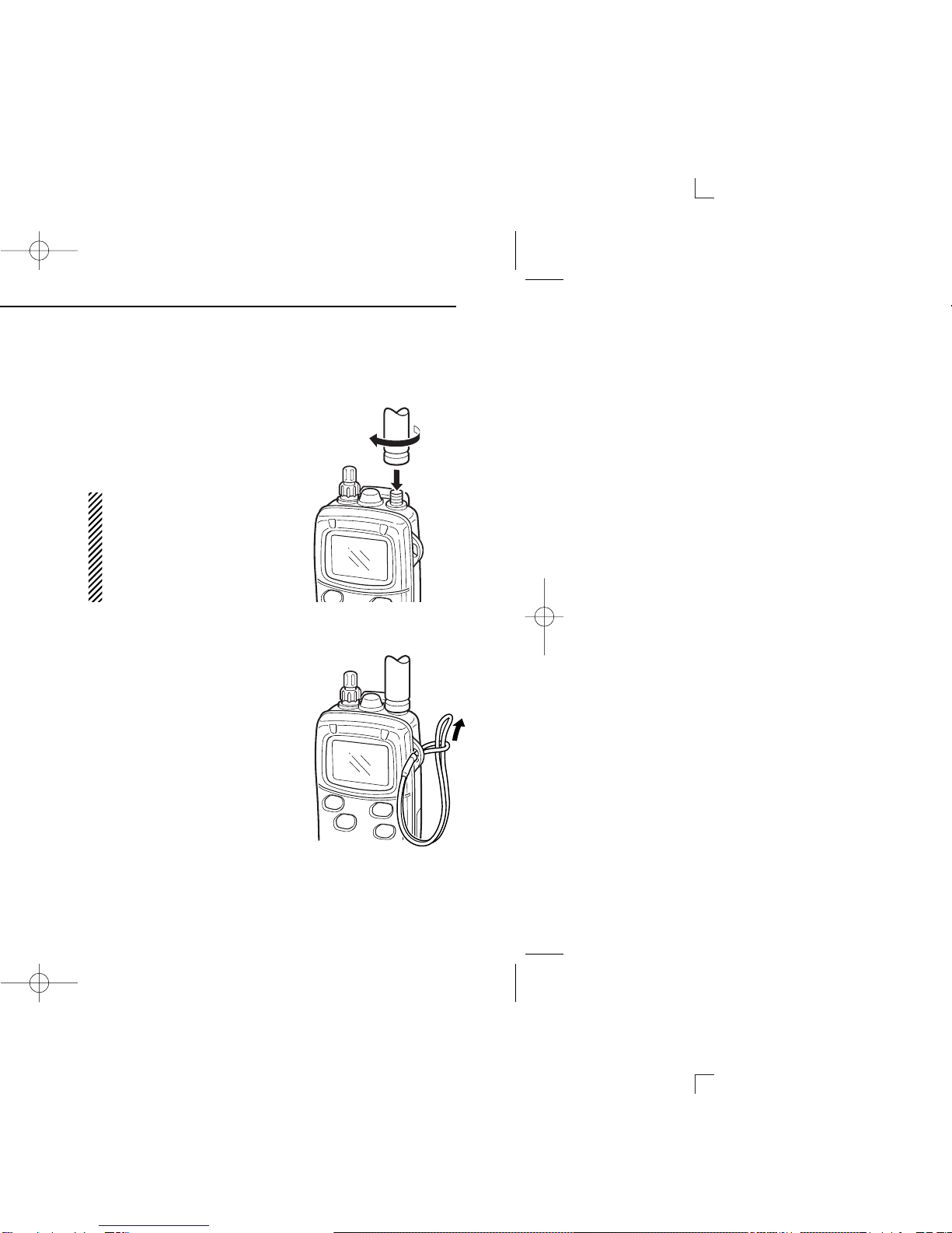
3 SUPPLIED ACCESSORIES AND ATTACHMENTS ....... 6
4 BASIC OPERATION .................................................. 7–11
■ Channel selection ........................................................ 7
■ Lock function ............................................................... 8
■ Automatic backlighting ................................................ 8
■ Receiving and transmitting .......................................... 9
■ Optional voice scrambler operation ........................... 10
■ Call channel programming ........................................ 11
5 SCAN OPERATIONS .............................................. 12–13
■ Scan types ................................................................ 12
■ Setting tag channels .................................................. 13
■ Starting a scan .......................................................... 13
6 DUALWATCH/TRI-WATCH ........................................... 14
■ Description ................................................................ 14
■ Operation .................................................................. 14
7 CHANNEL COMMENT PROGRAMMING ..................... 15
■ About the channel comment ..................................... 15
■ Channel comment programming ............................... 15
8 SET MODE .............................................................. 16–19
■ SET mode programming ........................................... 16
■ SET mode items ........................................................ 16
9 BATTERY CHARGING ............................................ 20–21
■ Caution ...................................................................... 20
■ Battery charging ........................................................ 20
10 SPEAKER-MICROPHONE .......................................... 22
■ Description ................................................................ 22
■ Attachment ................................................................ 22
11 TROUBLESHOOTING ................................................ 23
12 CHANNEL LIST ........................................................... 24
13 QUICK REFERENCE ................................................... 25
14 RECOMMENDATION ................................................... 26
15 SPECIFICATIONS AND OPTIONS ............................. 27
■ Specifications ............................................................ 27
■ Options ...................................................................... 27
IC-M1EURO V_3.qxd 03.5.9 17:00 Page d (1,1)

1
1
OPERATING RULES
DDPRIORITIES
qRead all rules and regulations pertaining to priorities, and
keep an up-to-date copy handy. Safety and distress calls
take priority over all others.
wYou must monitor channel 16 when you are not operating
on another channel.
eFalse or fraudulent distress signals are prohibited and pun-
ishable by law.
DDPRIVACY
qInformation overheard, but not intended for you, cannot
lawfully be used in any way.
wIndecent or profane language is prohibited.
DDRADIO LICENSES
(1) SHIP STATION LICENSE
You must have a current radio station license before using the
transceiver. It is unlawful to operate a ship station which is not
licensed.
Inquire through your dealer or the appropriate government
agency for a Ship-Radiotelephone license application. This
government-issued license states the call sign which is your
craft’s identification for radio purposes.
(2) OPERATOR’S LICENSE
A Restricted Radiotelephone Operator Permit is the license
most often held by small vessel radio operators when a radio
is not required for safety purposes.
The Restricted Radiotelephone Operator Permit must be
posted or kept with the operator. Only a licensed radio opera-
tor may operate a transceiver.
However, non-licensed individuals may talk over a transceiver
if a licensed operator starts, supervises, ends the call and
makes the necessary log entries.
Keep a copy of the current government rules and regulations
handy.
IC-M1EURO V_3.qxd 03.5.9 17:00 Page 1 (1,1)

■Panel description qVOLUME CONTROL [VOL]
Turns power ON and adjusts the audio level. (p. 9)
wSQUELCH CONTROL [SQL]
Sets the squelch threshold level. (p. 9)
ePTT SWITCH [PTT]
Transmits during push; receives during release. (p. 9)
rMONITOR SWITCH [MONI]
➥Opens the squelch and monitors the operating channel
while being pushed.
➥While turning power ON, enters the SET mode and is
used to select the SET mode contents when pushed. (p.
16)
tBATTERY PACK RELEASE BUTTON
• To remove the battery pack: Slide the battery release but-
ton upwards, then lift up the battery pack.
• To attach the battery pack:
Mate the notched ends of the
transceiver and the battery pack, and click the battery pack
into place firmly. Ensure that the battery is properly attached.
PANEL DESCRIPTION
2
2
r
t
e
u
i
w
q
y
!1
!2
!0
o
!4
!3
!5
Function display
(p. 4)
IC-M1EURO V_3.qxd 03.5.9 17:00 Page 2 (1,1)

yCHANNEL UP/DOWN SWITCHES [YY]/[ZZ]
➥Push either switch to change the operating channel.
(pgs. 7–9)
➥Checks tag channels or changes scanning direction dur-
ing scan. (p. 13)
➥Push either switch to change the setting during set
mode. (p. 16)
uCHANNEL 16 SWITCH [16•C]
➥Selects channel 16 when pushed. (p. 7)
➥Selects the call channel when pushed for 1 sec. (p. 7)
➥Enters call channel write mode when the call channel is
selected, and this switch is pushed for 3 sec. (p. 11)
iINTERNAL MICROPHONE (p. 9)
oSPEAKER-MICROPHONE CONNECTOR [SP MIC]
Connects the optional speaker-microphone. (p. 22)
!0 ANTENNA CONNECTOR
Connects the supplied antenna. (p. 6)
!1 DIAL/CHANNEL GROUP SWITCH [DIAL•I/U]
➥Selects and changes the regular channels. (p. 8)
➥Selects one of 2 regular channels in sequence when
pushed for 1 sec. (p. 8)
•International and U.S.A. channels (UK and Itarian ver-
sions only) are available for regular channels.
!2 DUALWATCH/TRI-WATCH SWITCH [DW•TRI]
➥Starts dualwatch when pushed momentarily. (p. 14)
➥Starts tri-watch when pushed for 1 sec. (p. 14)
➥Stops dualwatch/tri-watch when either is activated.
(p. 14)
➥Enters comment writing condition when pushed while
pushing and holding [MONI]. (p. 15)
!3 SCAN SWITCH [SCAN•TAG]
➥Starts and stops normal or priority scan when tag chan-
nels are programmed. (p. 13)
➥Sets the displayed channel as a tag (scanned) channel
when pushed for 1 sec. (p. 13)
➥While turning power ON, clears all tag channels in the
selected regular channel group when pushed. (p. 13)
➥Activates an optional voice scrambler function while
pushing [MONI]. (p. 10)
!4 TRANSMIT POWER/LOCK SWITCH [H/L•LOCK]
➥Changes high and low power when pushed. (p. 9)
•Some channels are set to low power only.
➥While pushing [MONI], push this key to select extra low
power. (p. 9: Not available for some versions)
➥Changes the lock function ON and OFF when pushed
for 1 sec. (p. 8)
!56 INTERNAL SPEAKER
PANEL DESCRIPTION
3
2
IC-M1EURO V_3.qxd 03.5.9 17:00 Page 3 (1,1)

■Function display
qBUSY INDICATOR (p. 9)
Appears while receiving a signal or while the squelch is
open.
wTRANSMIT INDICATOR (p. 9)
Appears while transmitting.
eCHANNEL GROUP INDICATORS (p. 8)
Appears “INT”when International; “USA”when U.S.A. (UK
and Itarian versions only) channel group is selected.
rCHANNEL NUMBER READOUT
•Indicates the selected operating channel number.
(pgs. 7, 8)
•In SET mode, indicates the selected condition.
(pgs. 16–19)
tATIS INDICATOR
Appears while ATIS function is activated. (German version
only)
yCOMMENT INDICATOR
•Indicates or scrolls operating channel comment, etc.
(pgs. 7, 13, 15)
•In SET mode, indicates or scrolls the selected item.
(pgs. 16–19)
PANEL DESCRIPTION
4
2
!1
q
w
e
r
t
yu
i
o
!2
!3
!4
!5
USA
INT
ATIS
CALL LOW
DUAL
DUP
TRI
TAG
!0
TX
BUSY
SCRM
IC-M1EURO V_3.qxd 03.5.9 17:00 Page 4 (1,1)

5
2
PANEL DESCRIPTION
uBATTERY INDICATOR
Indicates remaining battery power.
iLOCK INDICATOR (p. 8)
Appears while the lock function is activated.
oSUB CHANNEL READOUT
•Indicates channel 16 during priority scan. (p. 13)
•Indicates channel 16 during dualwatch or tri-watch.
(p. 14)
!0 DUPLEX INDICATOR
Appears when a duplex channel is selected.
!1 SCRAMBLER INDICATOR
Appears when the optional voice scrambler is activated.
(p. 10; Not available for some countries, due to local regulations)
!2 DUALWATCH/TRI-WATCH INDICATORS (p. 14)
•“DUAL”blinks during dualwatch.
•“TRI”blinks during tri-watch.
!3 LOW POWER INDICATOR (p. 9)
•Appears when low power is selected.
•Blinks when extra low power is selected.
(Not available for some versions)
!4 CALL CHANNEL INDICATOR (p. 7)
Appears when a call channel is selected.
!5 TAG CHANNEL INDICATOR (p. 13)
Appears when a tag channel is selected.
Indication
Battery level Full Middle Charging
required
No
battery
IC-M1EURO V_3.qxd 03.5.9 17:00 Page 5 (1,1)

6
3SUPPLIED ACCESSORIES AND ATTACHMENTS
DDSupplied accessories
The following accessories are supplied: Qty.
qFlexible antenna (FA-S57V) .................................1
wBattery pack (BP-215L) ........................................1
eBattery charger (AD-95) .......................................1
rAC adapter* (BC-122A/E/V*) ...............................1
tHandstrap ............................................................1
yBelt clip ................................................................1
uScrews for the belt clip (M3 ×4) ..........................2
iScrews for the AD-95 (M3.5 ×30)........................ 2
*Depending on version
DDBelt clip attachment
Attach the belt clip with the supplied screws. Conveniently
attaches to your belt.
DDFlexible antenna attachment
Insert the supplied antenna into
the antenna connector and screw
down the antenna as shown in
the diagram at right.
CAUTION: Attach the supplied
antenna securely for water-
proofing.
CAUTION: Transmitting with-
out an antenna may damage
the transceiver.
DDHandstrap attachment
Slide the handstrap through the
loop on the side of the transceiver
as illustrated at right.
Facilitates carrying.
NEVER use the supplied screws with-
out the belt clip, otherwise, the screw
holes may be damaged and the trans-
ceiver might cease to be waterproof.
Use the supplied screws only when at-
taching the belt clip.
IC-M1EURO V_3.qxd 03.5.9 17:00 Page 6 (1,1)

7
4
BASIC OPERATION
■Channel selection
DDChannel 16
Channel 16 is the distress channel. It is used for establishing
initial contact with another station and for emergency com-
munications. Channel 16 is automatically monitored during
both dualwatch and tri-watch. While standing by, you must
monitor channel 16.
➥Push [16] to select channel 16.
➥Push [DIAL] to return to the condition before selecting
channel 16, or push [Y]/[Z] to select operating channel.
DDCall channel
Each regular channel group has separate leisure-use call
channel. The call channel is monitored during tri-watch. The
call channels can be programmed (p. 11) and are used to
store your most often used channels in each channel group
for quick recall.
➥Push [16•C] for 1 sec. to select the call channel; of the se-
lected channel group.
•The “CALL”indicator and call channel number appear.
•Each channel group may have an independent call channel after
changing a call channel. (UK and Itarian versions only)
➥Push [DIAL] to return to the condition before selecting call
channel,or push [Y]/[Z] to select operating channel.
CALL
TAG
Scrolls the channel
comment, .
C
Push
for 1 sec.
INT
TAG
Scrolls the channel
comment, .
C
Push
INT
IC-M1EURO V_3.qxd 03.5.9 17:00 Page 7 (1,1)

DDInternational and U.S.A. channels
There are 57 International channels for the IC-M1EURO V.
qPush [DIAL] to select a regular channel.
•If a weather channel appears, push [DIAL] again.
wPush [Y]/[Z] to select a channel.
•“DUP”appears for duplex channels.
DDU.S.A. channels (UK and Itarian versions only)
For the UK and Itarian versions, there are 61 U.S.A. channels
in addition to 57 International channels. These channel
groups may be specified for the operating area.
qPush [DIAL] to select a regular channel.
•If a weather channel appears, push [DIAL] again.
wTo change the channel group, push [DIAL•I/U] for 1 sec. to
change the channel group to International or U.S.A..
ePush [Y]/[Z] to select a channel.
•Channels are memorized separately for each channel group.
■Lock function
This function electronically locks all keys and switches to pre-
vent accidental frequency changes and function access.
➥Push [H/L•LOCK] for 1 sec. to turn the lock function ON
and OFF.
•Only [PTT], [H/L] and [MONI] are functional.
■Automatic backlighting
This function is convenient for nighttime operation. The auto-
matic backlighting can be activated in SET mode. (p. 18)
➥Push any key except for [PTT] to turn the backlighting ON.
•The backlighting is automatically turned OFF 5 sec. after opera-
tion.
•Push [MONI] to turn the backlighting ON without changing the
operating condition.
4BASIC OPERATION
8
Appears when the
lock function is in use.
INT
IC-M1EURO V_3.qxd 03.5.9 17:00 Page 8 (1,1)

4
BASIC OPERATION
9
■Receiving and transmitting
qRotate [VOL] clockwise to turn power ON, then set to the
10 o’clock position.
•Turn [SQL] clockwise to mute any audio noise if necessary.
CAUTION:
If the comment, “WET INSIDE”, appears, turn the
power OFF immediately, and contact your local dealer, or ser-
vice center.
wPush [Y]/[Z] to select the desired channel.
•When receiving a signal, “BUSY”appears and audio is emitted
from the speaker.
•Further adjustment of [VOL] may be necessary at this point.
•Use the optional voice scrambler function for privacy. (p. 10)
ePush [H/L] to select the output power if necessary.
•“LOW”appears when low power is selected.
•Choose low power to conserve battery power, choose high
power for longer distance communications.
•Some channels are for low power only.
•An extra low power, Low 2, is available for short distance com-
munications. Push [H/L] while pushing [MONI] in such a case.
(Not available for some versions)
rPush and hold [PTT] to transmit, then speak into the mic.
•“TX”appears.
•Channel 70 cannot be used for transmission (GMDSS use only).
NOTE: Simplex channels, 3, 21, 23, 61, 64, 81, 82 and 83 CAN-
NOT be lawfully used by the general public in USA waters.
tRelease [PTT] to receive.
IMPORTANT: To maximize the readability of your trans-
mitted signal (voice), pause a few sec. after pushing [PTT],
hold the microphone 10 to 15 cm from your mouth and
speak at a normal voice level.
The transceiver has a power save function to conserve the
battery power which can be turned OFF. The power save
function activates automatically when no signal is received
for 5 sec. See page 18 for details.
qSet volume
eSet output power
qSet squelch
if required.
rSpeak into
microphone
Push to
transmit
r
t
Release to
receive
w
Set channel
CAUTION: Transmitting without an antenna may dam-
age the transceiver.
IC-M1EURO V_3.qxd 03.5.9 17:00 Page 9 (1,1)

10
4BASIC OPERATION
In some countries, this function is not available, since radio
law varies according to country. To activate the function,
an optional UT-98 or UT-112 is necessary. Ask your dealer
for details.
DDActivating the scrambler
The optional voice scrambler provides private communica-
tions. In order to receive or send scrambled transmissions,
you must first activate the scrambler function. To activate the
function, either an optional UT-98 or UT-112 is necessary. Ask
your dealer for availability, and details.
qSelect an operating channel
except channel 16.
wPush [SCN] while pushing and
holding [MONI].
•“SCRM”appears.
eTo turn the scrambler function
OFF, repeat step w.
•“SCRM”disappears.
DDProgramming scramble codes
There are 128 codes (00 to 127) available with UT-98 or 32
codes (01 to 32) available with UT-112 for programming. In
order to understand one another, all transceivers in your
group must have the same scramble code, as well as the
same scrambler unit. See page 19 for scrambling code set-
ting details.
RECOMMENDATION: Use the optional speaker-micro-
phone during voice scrambling operation for much clearer
audio readability.
SCRM
Appears when the voice
scrambler function is in use.
INT
■Optional voice scrambler operation
IC-M1EURO V_3.qxd 03.5.9 17:00 Page 10 (1,1)

11
4
BASIC OPERATION
■Call channel programming
The call channel key can be programmed to your most often-
used channels in each channel group for quick recall.
qPush [DIAL•I/U] for 1 sec. once or
twice to select the desired channel
group (USA, INT) to be pro-
grammed.
wPush [16•C] for 1 sec. to select the
call channel of the selected chan-
nel group.
•“CALL”and call channel number ap-
pear.
ePush [16•C] again for 3 sec. (until
long beep changes to 2 short beeps) to
enter call channel programming
condition.
•Call channel number and channel
group to be programmed flashes.
rPush [Y]/[Z] to select the desired
channel.
tPush [16•C] to program the dis-
played channel as the call channel.
•The call channel number and channel
group stop flashing.
TAG
USA
TAG
CALL
TAG
CALL
TAG
INT
INT
INT
TAG CALL
TAG CALL
TAG
INT
INT
IC-M1EURO V_3.qxd 03.5.9 17:00 Page 11 (1,1)

■Scan types
Scanning is an efficient way to locate signals quickly over a
wide frequency range. The transceiver has priority scan and
normal scan.
In addition, weather alert and an automatic scan start func-
tion is available for standby convenience. (pgs. 17, 18)
Set the tag channels (scanned channel) before scanning. (Clear
the tag channels which may inconveniently stop scanning, such as
those for digital communication use.)
Choose priority or normal scan in SET mode. (p. 17)
5SCAN OPERATIONS
NORMAL SCAN
Normal scan, like priority scan, searches through all tag
channels in sequence. However, unlike priority scan, chan-
nel 16 is not checked unless channel 16 is set as a tag
channel.
CH 01 CH 02
CH 88
CH 05 CH 04
CH 03
12
PRIORITY SCAN
Priority scan searches through all tag channels in se-
quence while monitoring channel 16. When a signal is de-
tected on channel 16, scan pauses until the signal disap-
pears; when a signal is detected on a channel other than
channel 16, scan becomes dualwatch until the signal dis-
appears.
WX*
CH 01
CH 16
CH 02
CH 05 CH 04
CH 03
IC-M1EURO V_3.qxd 03.5.9 17:00 Page 12 (1,1)

■Setting tag channels
For more efficient scanning, add desired channels as tag
channels or clear preset tag channels if they are unwanted
channels. Channels, set as non-tag channels will be skipped
during scanning. Tag channels can be assigned to each chan-
nel group (USA, INT) independently.
qSelect the desired channel group (USA, INT) by pushing
[DIAL•I/U] for 1 sec., if desired.
wSelect the desired channel to set as a tag channel.
ePush [SCN•TAG] for 1 sec., to be set the displayed chan-
nel as a tag channel.
•“TAG”appears in the function display.
rTo cancel the tag channel setting, push [SCN•TAG] for 1
sec.
•“TAG”disappears.
•Clearing all tag channels in the selected channel group
➥Turn power ON while pushing and holding [SCN•TAG] to
clear all tag channels in the channel group.
■Starting a scan
Set scan type, weather alert function, scan resume timer and
auto scan function in advance, using SET mode. (pgs. 17, 18)
qSelect the desired channel group (USA, INT) by pushing
[DIAL•I/U] for 1 sec., if desired.
•When the weather alert function is in use, select the desired
weather channel with [DIAL] and the channel selector.
wPush [SCN] to start priority or normal scan.
•The comment indicator flashes “SCAN”.
•The sub channel readout indicates “16”during priority scan.
•When a signal is received, scan pauses until the signal disap-
pears, or resumes after pausing for 5 sec. according to the SET
mode setting. (Channel 16 is still monitored during priority scan.)
•Push [Y]/[Z] to check the scanning tag channels, to change
the scanning direction or resume the scan manually.
eTo stop the scan, push [SCN].
•“SCAN”disappears.
•Pushing [PTT], [16•C], [DIAL] or [DW•TRI] also stops the scan.
5
SCAN OPERATION
13
Scan starts. Scan pauses when receiving a
signal and audio is emitted.
Push Push to stop
the scan.
TAG
DUP
TAG TAGBUSY
TA G
TA G
INT INT INT
[Example]: Starting a normal scan.
IC-M1EURO V_3.qxd 03.5.9 17:00 Page 13 (1,1)

14
6DUAL WATCH/TRI-WATCH
■Description
Dualwatch monitors channel 16 while you are receiving an-
other channel; tri-watch monitors channel 16 and the call
channel while receiving another channel.
■Operation
qSelect the desired operating channel.
wPush [DW•TRI] momentarily to start dualwatch; push
[DW•TRI] for 1 sec. to start tri-watch.
•“DUAL”flashes during dualwatch; “TRI”flashes during tri-watch.
•Beep tone sounds when a signal is received on channel 16.
•Tri-watch becomes dualwatch when receiving a signal on the call
channel.
eTo cancel dualwatch/tri-watch, push [DW•TRI] again.
[Example]: Operating tri-watch on INT channel 07.
DUALWATCH/TRI-WATCH SIMULATION
•If a signal is received on channel 16, dualwatch/tri-watch pauses
on channel 16 until the signal disappears.
•If a signal is received on the call channel during tri-watch, tri-
watch becomes dualwatch until the signal disappears.
•To transmit on the selected channel during dualwatch/tri-watch,
push and hold [PTT].
•If no signal is received, the transceiver enters the power saving
condition, after checking the operating channel every cycle.
Dualwatch Tri-watch
Call channel
Tri-watch starts.
Push for 1 sec.
Signal is received
on call channel.
Signal received on
channel 16 takes
priority.
Tri-watch resumes
after the signal
disappears.
TRI
INT
DUP
TRI
TAG
INT
DUP
TRI
TAG
BUSY
INT
CALL
DUP
TRI
TAG
BUSY
INT
DUP
TRI
TAG
IC-M1EURO V_3.qxd 03.5.9 17:00 Page 14 (1,1)

CHANNEL COMMENT PROGRAMMING 7
15
■About the channel comment
The IC-M1EURO V has a capability to assign up to 10-char-
acter channel comments for each operating channel, includ-
ing the weather channel. This provides easy recognition of
channel usage, or station names, etc.
When shipped from the factory, the IC-M1EURO V is pro-
grammed with default comments for each VHF marine chan-
nel. These defaults can be overwritten if desired.
DDAvailable characters
■
Channel comment programming
qPush [Y]/[Z] to select a channel to
program.
•Push [DIAL•I/U] for 1 sec. to select a
channel group, if necessary.
wWhile pushing [MONI], push [DW].
•The 1st character of the currently pro-
grammed comment flashes.
ePush [Y]/[Z] to select a character.
rPush [SCN] to move to the right; then
push [Y]/[Z] to select a character.
•Pushing [H/L], moves to left
tContinue until the desired characters
have been selected, then push [DW]
to return to normal operation.
(=)
(3)
(D)
(N)
(X)
(h)
(r)
(+)
(4)
(E)
(O)
(Y)
(i)
(s)
(–)(M)
(5)
(F)
(P)
(Z)
(j)
(t)
(6)
(G)
(Q)
(a)
(k)
(u)
(/)
(7)
(H)
(R)
(b)
(l)
(v)
(,)
(8)
(I)
(S)
(c)
(m)
(w)
(space)
(9)
(J)
(T)
(d)
(n)
(x)
(0)
(A)
(K)
(U)
(e)
(o)
(y)
(1)
(B)
(L)
(V)
(f)
(p)
(z)
(2)
(C)
(M)
(W)
(g)
(q)
INT
INT
INT
INT
INT
IC-M1EURO V_3.qxd 03.5.9 17:00 Page 15 (1,1)

SET mode is used to change the condi-
tion of 10 of the transceiver’s functions:
beep tone function, weather alert func-
tion, scan type (normal/priority), scan re-
sume timer, auto scan function, auto-
matic backlighting, power save function,
self check function, voice scrambler
type and scrambling code.
When no optional voice scrambler unit
is installed, voice scrambler type and
scrambling code cannot be set. (will not
be displayed)
qTurn power OFF.
wWhile pushing [MONI], turn power
ON and continue pushing [MONI]
until a beep is emitted.
•
After beep emission, release [MONI].
•Set mode item at comment indicator and
condition at channel number readout are
displayed.
rPush [MONI] to select the desired
item, if necessary.
tPush [Y]/[Z] to select the desired
condition of the item.
yTo exit SET mode, push [16].
•Turning power OFF, then ON again also
exits SET mode.
■SET mode items
DDBeep tone “BEEP”
You can select silent operation by turn-
ing the beep tones OFF, or you can
have confirmation beeps sound at the
push of a switch, by turning the beep
tones ON. The beep tone volume is
linked with [VOL].
8SET MODE
16
Automatic
backlighting
Power save
Scan resume timer
Scan type
Beep tone
Scrambler
unit selection
Scrambling
code
Self check function
Auto scan
Push
•SET mode construction
Push
Beep ON
(default)
Beep OFF
Push
■SET mode programming
IC-M1EURO V_3.qxd 03.5.9 17:00 Page 16 (1,1)
Table of contents
Other Icom Transceiver manuals