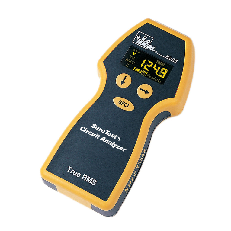
IDEAL SureTest 61-154 User manual

2
#61-154
#61-155
Introduction
The SureTest®family of circuit analyzers were designed to
troubleshoot branch circuits quickly, easily and accurately.
They have a patented technology that allows them to test
branch circuits under a full load condition to identify
hidden problems behind the wall that will not be
found with traditional testing methods.
Product Features
• True RMS
• Measures voltage drop under 12, 15 and 20-amp load
• Line voltage
• Peak voltage
• Frequency
• Ground impedance
• Hot and neutral conductor impedances
• Ground-neutral voltage
• Identifies proper wiring in 3-wire receptacles
• Identifies false (bootleg) grounds
• Verifies dedicated circuits (with 61-176 adapter)
• Tests GFCIs for proper operation
• Tests AFCI’s for proper operation (61-155)
• Includes carrying case
• Includes 1-ft. extension cord
General Operation
The SureTest®Circuit Analyzer, #61-154 and SureTest® Circuit Analzer,
#61-155 take only seconds to test each outlet and circuit under a full load.
They check for various wiring conditions, including: correct wiring, polarity
reversal, hot/ground reversal and no ground. A simple programming menu
gives access to measurements of line voltage, voltage drop under a full load
condition, ground-neutral voltage and line impedances. The ground fault
circuit interrupter (GFCI) test is performed separately and will disrupt the
electrical supply if a functional GFCI is present
The SureTest®w/AFCI, #61-155, will also test arc fault circuit interrupter
(AFCI) test to ensure that AFCI breakers protecting the circuit have been
installed correctly and are operating properly. This test is performed sepa-
rately in accordance with UL1436, and will disrupt the electrical supply if a
functional AFCI is present.
For proper troubleshooting of a branch circuit, insert the SureTest into the fur-
thest receptacle from the panel. Any discrepancies from a normal reading dur-
ing a measurement indicate that a problem has been detected in the circuit.
Allow at least 20 seconds between insertions. Repeatedly inserting the SueTest
into a receptacle will cause the unit to heat up which may affect the accuracies.
General Specifications
Case construction: ABS UL 94 V/0/5VA rated
Operating Range: 108 to 132 Volts
Display: 97x32 Pixel Graphics Display with backlight
Dimensions: 6.5” x 3” x 1”
Weight: 9.4oz
Environmental Specifications
Operating Temp.: 0° C to 50° C
Storage Temp.: 0° C to 50° C
Humidity: <80% RH
Altitude: 2000m (6667 ft.)
Safety: Designed to IEC 1010-1 UL3111
Input Rating: 150VAC Category III
Overvoltage Category: Cat III: Distribution level mains, fixed installations
Cat II: Local level mains, appliances, portable
equipment
Cat I: Signal level, special equipment or parts of
equipment, telecommunications, electronics
Pollution Degree 2: Do not operate in environments where conductive
pollutants may be present
WARNING: Do not use on outputs from UPSsystems, light
dimmers or square wave generating equipment.
SureTest®Circuit Analyzer and
SureTest®w/AFCI Instructions
Sold by:
http://www.TWAcomm.com
Toll Free: (877) 892-2666

Accuracy
Line Voltage: 108.0 - 132.0VAC 1.0% +/- 1 digit
Peak Voltage 151.0 - 185.0VAC 1.0% +/- 1 digit
Frequency: 45.0 - 85.0Hz 1.0% +/- 1 digit
Voltage Drop: 0.1% - 2 0 . 0 % 1.0% +/- 1 digit
Ground-Neutral Voltage: 0.0 - 24.0 VAC 1.0% +/- 1 digit
Impedances: 0.01 - 9.99Ω1.0% +/- 1 digit
GFCI Trip Time : 1mS - 7000mS 1.0% +/- 1 digit
SureTest®Circuit Analyzer
1. Menu Structure
2. Menu Buttons
3. Display
4. GFCI Test Button
5. AFCI Test Button
Menu Structure
The measurements taken by the SureTest model ST-2D are organized into a
simple menu. The first measurement in each menu selection is listed on the
face of the unit. To the right of each menu is the unit of measure for the
tests performed within that menu. The grid, and up and down arrows are
representative of how the display will indicate the units position within the
menu. The grid has four regions (one for each menu selection). When the
unit is in the line voltage menu, the first section of the grid will be shaded in
on the display to indicate that the unit is in the first menu selection. When
the unit is in the Voltage Drop menu, the second section of the grid of the
grid will be shaded in on the display to indicate that the unit is in the sec-
ond menu selection. This follows for the Ground-Neutral Voltage and Line
Impedance menus as well.
Additional tests are located in the sub-menu for each of these menu selec-
tions. An up arrow indicates that the unit is in the main menu, and a down
arrow indicates that the unit is in a sub-menu. This will be displayed just
under the menu grid on the unit’s display. Using the menu grid and menu
level indication will help the user step through the menu as indicated by the
menu structure listed on the face of the unit.
Menu Buttons
The SureTest model ST-2D uses two buttons to navigate through the mea-
surement menu. The down arrow button (↓) moves the unit forward to the
next menu selection. If the SureTest is on the last menu selection (Line
Impedance), pressing the down arrow button returns the unit to the first
menu selection (Line Voltage).
The side arrow button (→ ) moves the unit through all the measurements
within the menu selection. If the SureTest is in the last measurement of the
menu selection, pressing the side arrow button returns the unit to the first
measurement.
The quick reference guide at the end of this manual lists all of the available
measurements in the SureTest menu.
Display
The graphical LCD on the SureTest ST-2D indicates the value of the measure-
ment function, the test being performed and the position within the menu
structure.
1. Test results
2. Measurement Icon
3. Menu Structure Icon
Measurement Icon
The measurement icon is located on the right-hand side of
the display. The icon consists of the measurement symbol
and text to describe which test is being measured. For exam-
ple, the following icon indicates that the numerical value dis-
played is the True RMS line voltage.
3
3
#61-155
GFCI
AFCI
Line Voltage (V)
Voltage Drop (%)
G-N Voltage (V)
Line Impedance ( )
RMS
True
S
u
r
e
e
T
s
t
2
4
5
1
V
RMS
4
Sold by:
http://www.TWAcomm.com
Toll Free: (877) 892-2666

If the wiring is OK, enter the SureTest measurement menu by pressing the
down arrow button (↓). If no ground condition exists, the user may enter
the measurements menu, but only the line voltage and voltage drop mea-
surements are available. In a polarity reversal condition, the SureTest will
not be able to take any measurements, so the unit will not be able to access
the measurement menu under these conditions. In a hot/ground reversal,
open hot or open neutral condition, the unit will not have power for any
measurements, so the unit will not display any information.
False Ground Indication
The neutral conductor can only be bonded to the ground conductor at the
main neutral buss, where a large copper conductor carries all the return and
faulted current back to the earth. Sometimes through error or ignorance, the
neutral and ground are connected upstream from the service entrance. This
condition is referred to as a false or bootleg ground. Common receptacle
testers will test this condition as a normal wiring condition.
The SureTest model ST-2D will analyze the neutral and ground conductors
to identify a potential false ground condition. If the unit is within 15 feet of
a connection between neutral and ground, the SureTest will indicate a
potential false ground condition.
A false ground may also be indicated if the receptacle is within 15 feet of
the neutral-ground bonding point at the main panel. After the false ground
condition has been checked out, press the down arrow button (↓) to enter
the measurement menu.
Menu Structure Icon
The menu structure icon is to the right of the measurement
icon. It consists of a grid and either an up or down arrow.
The grid on the display has four regions that correspond to
each of the menu selections as listed on the face of the unit.
The appropriate region is shaded in to indicate which test is
being performed. If the unit is performing any test within the
Line Voltage menu or sub-menu, the first region is shaded.
The arrow underneath the grid indicates whether the unit is in
the main menu or sub-menu. An up-arrow (↑) indicates that
the unit is in the main menu, and a down arrow (↓) indicates that the unit
is in a sub-menu. If the unit is performing a test within the Line Voltage
sub-menu, the first region of the grid will be shaded with a down arrow
underneath the grid.
GFCI Test Button
This button activates the GFCI test. This test can be activated from any
point within the SureTest menu.
AFCI Test Button
This button activates the AFCI test. This test can be activated from any
point within the SureTest menu.
Wiring Verification
Immediately after being inserted into a receptacle, the
SureTest checks for proper wiring. While it is performing
this test, the IDEAL logo will be displayed on the LCD.
The SureTest 61-154 checks for the following conditions
and indicates the test result on the display next to the
receptacle test icon.
Wiring Condition Display Indication
Normal Wiring OK
No Ground Error No Ground
Polarity Reversal Error Rev Polarity
Hot/Ground Reversal No Display
Open Hot/Open Neutral No Display
56
WARNING:
An indication of “NoGround” in the wiring verification test indicates a safety
hazard is present. Defective grounds must be repaired prior to the GFCI test.
WARNING:
If the SureTest®unit does not power up when plugged, contact a licensed
electrician to diagnose the problem.
Sold by:
http://www.TWAcomm.com
Toll Free: (877) 892-2666

87
SureTest Measurements
Use the down arrow (↓) and side arrow (→ ) buttons to navigate through
the measurement menu as outlined in the menu buttons section of this man-
ual. There are four measurement menu options; line voltage, voltage drop,
ground-neutral voltage and line impedance.
Line Voltage Measurements
There are three tests within the line voltage menu.
Measurement Icon
Line Voltage
Peak Voltage
Frequency
The line voltage measurement is the first measurement within this menu
selection. Pressing the side arrow button (→ ) moves the unit from mea-
surement to measurement within the line voltage menu. Pressing the down
arrow button (↓) moves the unit to the next menu selection – Voltage Drop.
Troubleshooting Tips
The line voltage tests are conducted without a load. If these results are not
met, it could be a problem with the circuit, or a load on the circuit. To
determine what may be causing the problem, turn off the loads on the circuit
and re-check. If the test results do not change, than the problem may be
within the circuit. If the test results return to normal, than the problem is
being caused by one or more of the loads on the circuit.
Measurement Expected Problem Possible Possible
Result Causes Solutions
Line Voltage 108-132V High/low - Too much load - Redistribute the
line on branch circuit load on the circuit
voltage - High resistance - Locate high
connection within resistance
the circuit or at connection/device
the panel and repair/replace
- Supply voltage - Consult power
too high/low company
Peak Voltage 153-185V High/low - Supply voltage - Consult power
peak too high/low company
voltage - Distorted wave - Evaluate #
form caused by electronic devices
electronic on circuit and
equipment on redistribute if
the line necessary
Frequency 60Hz High/low - Supply frequency - Consult power
frequency too high/low company
V
RMS
HZ
V
PEAK
Sold by:
http://www.TWAcomm.com
Toll Free: (877) 892-2666

109
Voltage Drop Measurements
There are three tests within the voltage drop menu.
Measurement Icon
Voltage Drop at 15-Amp load
Voltage Drop at 12-Amp load
Voltage Drop at 20-Amp load
The National Electrical Code recommends 5% as the maximum voltage drop
for branch circuits for reasonable efficiency (NEC article 210-19. FPN 4).
High voltage drop could be an indication of a high resistance connection
within the circuit, undersized wire for the load or length of run, or a defective
device on the branch circuit.
All of the voltage drop measurements are taken under an actual 12-Amp load
and extrapolated for 15 amp and 20 amp measurements. This allows the
user to test a 15-Amp rated circuit at full capacity or 80% capacity, and test a
20-Amp rated circuit under a full capacity. Voltage drop under a 15 amp
load is the first measurement within this menu selection. Pressing the side
arrow button (→ ) moves the unit from measurement to measurement within
the line voltage menu. Pressing the down arrow button (↓) moves the unit
to the next menu selection – Ground-Neutral Voltage.
Troubleshooting Tips
Measurement Expected Problem Possible Possible
Result Causes Solutions
Voltage Drop <5% High - Too much load - Redistribute the
voltage on the branch load on the circuit
drop circuit
- Undersized wire - Check code
for length of run requirements and
re-wire if
necessary
- High resistance - Locate high
connection within resistance
the circuit or at the connection/device
panel and repair/replace
Ground-Neutral Voltage Measurement
There is only one test within the Ground-Neutral Voltage menu. In a single-
phase circuit, high ground-neutral voltage indicates excessive leakage
between the neutral and ground conductors. In a 3-phase circuit with a
shared neutral, a high ground-neutral voltage could also indicate unbalanced
load between the three phases, or harmonic distortion on the shared neutral.
A reading of less than 2 Volts usually indicates a usable outlet. An excessive
ground-neutral voltage may result in inconsistent or intermittent equipment
performance. Pressing the down arrow button (↓) moves the unit to the
next menu selection – Line Impedance.
Troubleshooting Tips
Measurement Expected Problem Possible Possible
Result Causes Solutions
Ground-Neutral <2V High G-N - Current leaking - Identify source of
Voltage voltage from neutral leakage (multiple
to ground l bonding points)
- Unbalanced - Check load balance
3-phase system and re-distribute load
- Harmonic content - Oversize neutral or
returning on neutral de-rate transformer
in 3-phase system to dissipate heat
15A
%
DROP
20A
%
DROP
12A
%
DROP
Sold by:
http://www.TWAcomm.com
Toll Free: (877) 892-2666

11
Line Impedance Measurements
There are three tests within the line impedance menu.
Measurement Icon
Hot conductor impedance
Neutral conductor impedance
Ground impedance
The hot conductor impedance measurement is the first measurement within
this menu selection. Pressing the side arrow button (→ ) moves the unit
from measurement to measurement within the line impedance menu.
Pressing the down arrow button (↓) returns the unit to the first menu selec-
tion – Line Voltage.
Troubleshooting Tips
Measurement Expected Problem Possible Possible
Result Causes Solutions
Hot conductor <0.48Ω/ High - Too much load - Redistribute the
impedance foot of 14 conductor on branch circuit load on the circuit
gauge wire impedance - Undersized - Check code
<0.03Ω/ wire for length of requirements and
foot of 12 run re-wire if necessary
gauge wire - High resistance - Locate high
<0.01Ω/ connection within resistance
foot of 10 the circuit or at connection/device
gauge wire the panel and repair/replace
Neutral <0.48Ω/ High - Too much load - Redistribute the
conductor foot of 14 conductor on branch circuit load on the circuit
impedance gauge wire impedance - Undersized wire - Check code
<0.03Ω/ for length of run requirements and
foot of 12 re-wire if necessary
gauge wire - High resistance - Locate high
<0.01Ω/ connection within resistance
foot of 10 the circuit or at the connection/device
gauge wire panel and repair/replace
Ground <1Ωto High - Too much load - Redistribute the
impedance protect ground on branch circuit load on the circuit
personnel impedance - Undersized - Check code
<0.25Ωwire for length requirements and
to protect of run re-wire if necessary
equipment - High resistance - Locate high
connection within resistance
the circuit or at connection/device
the panel and repair/replace
12
Ω
H
Ω
G
Ω
N
Sold by:
http://www.TWAcomm.com
Toll Free: (877) 892-2666

AFCI Testing (#61-155 only)
The SureTest® w/AFCI applies a high current pulse onto the line within 8
consecutive half-cycles in accordance with UL1436. A functional AFCI
breaker will disconnect the power to the circuit. To restore power, reset the
breaker at the panel.
To activate the AFCI test, press and hold the AFCI button from anywhere
within the measurement menu. The unit will countdown from 3 and display
a lighting bolt to let the user know that the test is being performed. if the
user releases the AFCI test button before the lighting bolt appears, the test
will be aborted.
If the circuit is protected by an AFCI breaker it will disconnect power, and
the display on the unit will go out.
If the AFCI fails to trip, the SureTest® will show invalid on the display, indi-
cating that the AFCI may be installed incorrectly, the AFCI may be defective,
or the line impedance was too high to allow sufficient current to pass
through the circuit for a proper test. Use the SureTest®to identify and locate
the cause of the high resistance and repair the circuit.
Troubleshooting Tips
Measurement Expected Problem Possible Possible
Result Causes Solutions
AFCI Test AFCI trips AFCI does - AFCI may be - Check wiring and
not trip installed re-wire device
(invalid incorrectly according to
test) manufacturer’s
instructions
- AFCI may be - Repair/replce GFCI
defective - Locate high
- High line resistance/device
impedance (>Ω) and repair/replace
does not allow
enough current
to flow through
circuit to run
AFCI test
GFCI Testing
The SureTest®applies 6mA though a fixed resistor to trip the GFCI. A func-
tional GFCI will disconnect the power. The reset button for the GFCI may be
at the receptacle or at the panel.
To activate the GFCI test, press the GFCI button (GFCI) from anywhere with-
in the measurement menu. The actual current being bled from hot to neutral
will be displayed. (6mA is the nominal current sent through the fixed resis-
tor. The actual current will vary depending on the line voltage per UL1436.)
Test in progress will than appear on the display to let the user know that the
GFCI test is being performed. The unit will bleed the current until the GFCI
trips, or up to 6 seconds.
If the GFCI device is functioning properly, it will disconnect power, and the
display on the unit will go out. When the circuit is reset and power is
restored, the unit will display the actual time that the GFCI took to trip the
circuit. Pressing the down arrow button (↓) resets the unit and returns it to
the wiring verification mode.
If the GFCI fails to trip, the SureTest will show invalid on the display, indicat-
ing that the GFCI may be installed incorrectly, or the GFCI may be defective.
Troubleshooting Tips
Measurement Expected Problem Possible Possible
Result Causes Solutions
GFCI Test GFCI trips GFCI does - GFCI may be - Check wiring and
with trip not trip installed incorrectly re-wire device
time (invalid according to
<200mS test), or manufacturer’s
trip time instructions
>200mS - GFCI may be - Repair/replace
defective GFCI
13
Note: The SureTest will not allow the AFCI test if a wiring problem exists.
Repair the circuit before testing.
14
Note: The SureTest will not allow the GFCI test if a no ground condition
exists. Repair the ground circuit before testing.
Note: In order to test GFCIs in a 2-wire system (no ground), the #61-175
ground continuity adapter must be used. Connect the alligator clip on the
adapter to a ground, such as a metal water or gas pipe.
Sold by:
http://www.TWAcomm.com
Toll Free: (877) 892-2666

15 16
Optional Accessories
#61-175 Ground Continuity Adapter
This adapter allows the operator to verify that a cabinet or equipment chas-
sis has been properly bonded to the system ground. Plugging the SureTest
into the ground continuity adapter will isolate the SureTest from the electri-
cal ground. If the equipment is properly grounded, then connecting the alli-
gator clip from the ground continuity adapter to the cabinet or equipment
chassis should provide a pathway to ground, and consequently a normal
wiring condition on the SureTest.
After the ground continuity adapter has been connected, the SureTest can be
used to measure the ground impedance of the cabinet or equipment chassis.
See the section on Line Impedance Measurements for test instructions.
This adapter can also be used to test GFCI receptacles on 2-wire circuits.
Connect the alligator clip on the adapter to a ground, such as a metal water
or gas pipe prior to testing the GFCI.
#61-176 Isolated Ground Adapter
This adapter allows the operator to verify that a receptacle is completely iso-
lated from the system ground that is bonded to other devices on the branch
circuit.
Test the ground impedance of the receptacle and make a note of the results
(See the section on Line Impedance Testing for details). Remove the
SureTest and plug it into the isolated ground adapter. Attach the alligator
clip to the center receptacle screw or metal junction box, and re-insert the
SureTest into the receptacle and make a note of the result.
The isolated ground adapter creates a parallel pathway to ground, which
results in a lower reading on a receptacle with an isolated ground. If the
two readings are the same, than the receptacle does not have an isolated
ground. If the reading taken with the isolated ground adapter is lower, than
the receptacle has an isolated ground.
#61-183 Lighting Circuit Adapter
This adapter allows the operator to use
the SureTest on residential lighting cir-
cuits to verify that bedroom lighting cir-
cuits are protected by the AFCI (61-155
only), and identify and locate high resis-
tance points within the circuits.
Simply plug the lighting circuit adapter into the IEC connection on the top
of the SureTest, and connect the hot (red), neutral (white) and ground
(green) alligator clips onto the circuit. Correct test results are dependant on
making good connections with the alligator clips onto the circuit.
Note: The SureTest is designed for 120V circuits only. Do not exceed the
rating of the SureTest with this adapter.
Sold by:
http://www.TWAcomm.com
Toll Free: (877) 892-2666

1817
Locating High Resistance Connections
Troubleshooting to identify the cause of the high impedance within the elec-
trical system is actually quite simple. First measure the voltage drop at the
furthest receptacle from the panel on the branch circuit under test. If the
voltage drop is high, than further investigation is necessary.
Testing the remaining receptacles in sequence, from next furthest from the
panel to the closest to the panel, will identify the problem.
If the voltage drop reading changes significantly from one receptacle to the
next, then the problem is a high impedance point at or between the two
receptacles. It is usually located at a termination point, such as a bad splice
or loose wire connection, but it might also be a bad receptacle.
If the reading steadily decreases as you get closer to the panel, with no sig-
nificant decreases between receptacles, then the wire may be undersized for
the length of run, or for the load on the line. Check at the panel to see if the
wire is sized per code, and measure the current on the branch circuit.
The reading may not decrease at all from the last receptacle to the first. This
would indicate that the problem could be at the first splice, or at the panel
itself. Most poor panel connections show up as hot spots on the panel.
These can be checked quickly with an infrared temperature meter.
Quick Reference Guide Measurement Menu
Line Voltage Menu
Press →Press→Press→
Line Voltage for next Peak Voltage for next Frequency for first
Measurement test Measurement test Measurement test
Press↓to advance to Voltage Drop Menu
Voltage Drop Menu
Voltage Drop Press →Voltage Drop Press →Voltage Drop Press →
Measurement for next Measurement for next Measurement for first
@ 15-Amp test @ 12-Amp test @ 20-Amp test
Press ↓to advance to Ground-Neutral Voltage Menu
Ground-Neutral Voltage Menu
Ground-
Neutral
Voltage
Measurement Press ↓to advance to Line Impedance Menu
Line Impedance Menu
Neutral
Hot Conductor Press →Conductor Press →Ground Press →
Impedance for next Impedance for next Impedance for first
Measurement test Measurement test Measurement test
Press ↓ to advance to Line Voltage menu
Sold by:
http://www.TWAcomm.com
Toll Free: (877) 892-2666

19
IDEAL INDUSTRIES, INC.
Sycamore, IL 60178, U.S.A.
800-435-0705 Customer Assistance
www.idealindustries.com
ND 3595-2 Made in U.S.A.
Service of Double-Insulated Appliances
In a double-insulated controller, two systems of insulation are provided
instead of grounding. No equipment grounding means is provided in the
cordset of a double-insulated product, nor should a means for equipment
grounding be added to the controller. Servicing a double-insulated
controller requires extreme care and knowledge of the system, and should
be done only by qualified service personnel. Replacement parts for a
double-insulated controller must be identical to the parts they replace.
Lifetime Limited Warranty
This meter is warranted to the original purchaser against defects in material
or workmanship for the lifetime of the meter. During this warranty period,
IDEAL INDUSTRIES, INC. will, at its option, replace or repair the defective
unit, subject to verification of the defect or malfunction. This warranty does
not apply to defects resulting from abuse, neglect, accident, unauthorized
repair, alteration, or unreasonable use of the instrument.
Any implied warranties arising out of the sale of an IDEAL product, includ-
ing but not limited to implied warranties of merchantability and fitness for a
particular purpose, are limited to the above. The manufacturer shall not be
liable for loss of use of the instrument or other incidental or consequential
damages, expenses, or economic loss, or for any claim or claims for such
damage, expenses or economic loss.
State laws vary, so the above limitations or exclusions may not apply to you.
This warranty gives you specific legal rights, and you may also have other
rights, which vary from state to state.
Warranty limited solely to repair or replacement; no warranty of mer-
chantability, fitness for a particular purpose or consequential damages.
Sold by:
http://www.TWAcomm.com
Toll Free: (877) 892-2666
This manual suits for next models
1
Table of contents
Other IDEAL Measuring Instrument manuals

IDEAL
IDEAL SPLIT-JAW 61-096 User manual

IDEAL
IDEAL 61-920 User manual

IDEAL
IDEAL 61-920 User manual

IDEAL
IDEAL 61-797 User manual

IDEAL
IDEAL 660A TRMS 61-763 User manual

IDEAL
IDEAL 61-686 User manual

IDEAL
IDEAL 61-686 User manual

IDEAL
IDEAL 61-744 User manual

IDEAL
IDEAL TightSight 61-773 User manual

IDEAL
IDEAL niPRO Gbis User manual

IDEAL
IDEAL TightSight 61-763 User manual

IDEAL
IDEAL 61-764 User manual

IDEAL
IDEAL AS10 User manual

IDEAL
IDEAL 61-737 Use and care manual

IDEAL
IDEAL 61-702 User manual

IDEAL
IDEAL TightSight 61-773 User manual

IDEAL
IDEAL SureTest 61-164 User manual

IDEAL
IDEAL 61-797 User manual

IDEAL
IDEAL 61-734 User manual

IDEAL
IDEAL 61-954 User manual