Idmed ToFscan User manual

User Manual ToFscan 1
User Manual
NeuroMuscular Transmission Monitor
Version 1.7 EN - DR
Last Update 2018/07/12
Ref: TOF-IFU_EN_DR

User Manual ToFscan

User Manual ToFscan 3
CONTENTS
About this product............................................................................................... 4
Indications for use ............................................................................................... 4
Expected performance....................................................................................... 4
Important Information about the use of this device........................... 4
Safety measures................................................................................................... 5
Warning................................................................................................................................5
Caution.................................................................................................................................6
Explanation of the symbols .......................................................................................8
I General information ......................................................................................... 9
Overview of the ToFscan and its accessories .................................................9
Main menu, Display screen........................................................................................9
Menu selection .................................................................................................................9
Battery / AC power supply operation..................................................................9
II ToFscan setup ...................................................................................................10
Cable / Cable connection ....................................................................................... 10
Electrodes.......................................................................................................................... 10
Positioning of the electrodes .................................................................................. 10
Placing of the sensor.....................................................................................................11
Skin impedance..............................................................................................................12
Connecting the cable to the ToFscan ................................................................13
Reference ...........................................................................................................................13
III Using the ToFscan..........................................................................................13
General principle............................................................................................................13
TOF mode.......................................................................................................................... 14
TET mode........................................................................................................................... 15
DBS mode.......................................................................................................................... 15
PTC Mode........................................................................................................................... 15
ST Mode.............................................................................................................................. 16
Parameters Menu...........................................................................................................17
IV Servicing, Disinfection cleaning..............................................................17
Preventive servicing, Maintenance.......................................................................17
Battery / Battery charge ........................................................................................... 18
Cleaning............................................................................................................................. 18
Diagnostic / Malfunction........................................................................................... 19
V End-of-life disposal / Recycling...............................................................19
VI Technical specications and warranty ...............................................19
Environment.................................................................................................................... 22
VII Accessories.....................................................................................................23

User Manual ToFscan 4
About this product
This operating manual provides the instructions on how to congure and use the ToFscan from
IDMED. It also describes the specic procedures to clean and verify the device as part of the
necessary maintenance. This manual is intended to be used only by qualied medical personnel.
Keep this operating manual with the ToFscan. A service manual is available for the technicians in
charge of servicing.
Before you start, please make sure you read carefully and understand the safety information
contained in this manual.
Indications for use
The ToFscan is a neuromuscular transmission monitor for monitoring the neuromuscular block of a
patient in the operating theatre, recovery room or intensive care unit.
The effect of neuromuscular blocking agents (NMBAs) is monitored by measuring the
acceleration of the muscle movement (acceleromyography) or by visually observing
muscle contractions consequent to electrical stimulation. The ToFscan has a three-dimensional
acceleration sensor (accelerometer) to detect and quantify a patient’s muscle movement. For the
thumb (contracting adductor pollicis), the sensor is directly integrated into the nger’s splint, making
it possible to obtain its optimal and reproducible positioning. For the eyebrow and big toe sensors, a
correct sensor position allows for optimal and reproducible measurement.
Expected performance
The following features are essential performance of the device:
- Stimulation of an anesthetized patient with electrical pulse: repeated or single 200µs square pulse,
20mA to 60mA intensity. All values within +/- 10%
- Allow several stimulation sequences in accordance to usual practice, TOF, DBS, TETANUS, PTC, ST
- Allow comparison of muscle response placed on the thumb, toe or close to the eyebrow, during
TOF (Train of Four) stimulation. It aims to detect movement and acceleration ratio between last and
rst movement.
The ToFscan may temporarily not display result during transient electromagnetic disturbances such
as the use of electrosurgery device. In that case, the ToFscan will maintain the safety of the patient
and the user.
Important Information about the use of this device
The compact ToFscan is intended for use by health professionals (anaesthetists, doctors or fully
qualied nurse anaesthetists) specially trained in the use of this instrument. The device and all of the
settings associated with it are designed for use on adult and paediatric patients in hospital or health
institutions so that the patient’s neuromuscular block level can be monitored.
The ToFscan measurements of the patient’s muscular response can be used to monitor the effects
of neuromuscular blocking agents.
The interpretation of ToFscan results must always be subjected to clinical assessment and
compared against other observed clinical signs. Sole reliance on the results or values rendered by
the ToFscan for the monitoring of curare-administered patients, is strongly discouraged. The values
measured in patients with neurological disorders, nervous system disorders, Bell’s palsy, myasthenia
or general neuromuscular disorders must be carefully interpreted.
The ToFscan is compliant with the European directive on medical devices and with the current
regulatory requirements of the countries where it is distributed.

User Manual ToFscan 5
For further information, kindly contact the ToFscan manufacturer IDMED through his internet website
(www.idmed.fr) or by mail at the following address:
IDMED
Hôtel Technoptic
2 rue M.DONADILLE
13013 MARSEILLE FRANCE
ToFscan® and IDMED® marks are property of IDMED company (France).
SAFETY MEASURES
INTRODUCTION
Read this entire manual carefully before using the ToFscan.
WARNINGS, CAUTIONS, NOTES
The terms Warning, Caution and Note have specic meanings in this manual.
• A WARNING cautions against certain actions or situations likely to cause bodily harm or death.
• The word CAUTION warns against actions or situations likely to damage the equipment, produce
inaccurate data or cancel a procedure, even if bodily harm is less than likely to occur.
• A NOTE provides relevant information about a function or procedure.
EXPLANATION OF THE SYMBOLS
The symbols which may be displayed on the ToFscan screen are recapitulated and explained at the
end of this section.
Warning
Risk of explosion: do not use the ToFscan in a ammable environment or in places where
ammable anaesthetic products are accumulated.
The ToFscan is not designed to operate in an environment where there are SCANNERS, M.R.I.’s
or any other device creating large magnetic elds. The same applies for short-wave or
medium-wave treatment devices.
The electrode cables, electrodes and connections must not come into contact with any other
item, conductive or otherwise.
In order to reduce the risk of burns when using high-frequency surgical devices, do not place
the ToFscan stimulation electrodes between the surgical site and the electrode leading back to
the electrosurgical unit.
Simultaneously connecting a patient to a high-frequency surgical device may cause burns at
the contact points of the ToFscan electrodes and cause damage to the device.
Never use the ToFscan at the same time that debrillation devices are being used.
Like all neuromuscular transmission monitor, the ToFscan must be connected to electrical
stimulation electrodes capable of supporting up to 300 volts with 60 mA current. The contact
surface of the electrodes must be greater than 1.8cm².

User Manual ToFscan 6
The output from electrical stimulation causes nociceptive stimulations and the intensity of
these stimulations must be adapted to the patient’s analgesic level.
Do not use the ToFscan on patients wearing pacemakers without verifying and identifying the
possible consequences.
Never use the ToFscan near short-wave or medium-wave treatment devices.
Prior to use, check that no other equipment, device or material is in contact with the electrodes.
Sensors and electrodes should only be in contact with clean and healthy skin
Prior to each use, check that the device, the display and the cables (electrodes and sensors) are
not damaged. Do not use if a part is damaged
Handle the device with care to prevent any fall.
The ToFscan should be used during a limited time on one patient at a time and cleaned between
patients.
The ToFscan can be used fully or partially during the surgery. The duration should not exceed
24H.
After positioning one of the sensors in contact with the patient, check regularly at least every 2 to
3 hours that the sensor does not cause excessive pressure or stress on the patient’s skin. If skin
appearance changes, change the site sensor.
In order to prevent electromagnetic disturbance, keep minimum separation from RF
communication equipment of 30cm
Use of this equipment adjacent to or stacked with other equipment should be avoided because
it could result in improper operation. If such use is necessary, this equipment and the other
equipment should be observed to verify that they are operating normally
Use of accessories, transducers and cables other than those specied or provided by the
manufacturer of this equipment could result in increased electromagnetic emissions or
de-creased electromagnetic immunity of this equipment and result in improper operation.
Use cables other than the one recommended by the manufacturer of this equipment could
result in increased cyber security risks.
Caution
Read this entire manual carefully before using the ToFscan.
Never put the ToFscan or any of its parts or accessories into an autoclave.
The device or its parts are not to be immersed in, splashed or cleaned with liquids.
The ToFscan and its parts are not suitable for the processes of gas, radiation (gamma or other),
water bath, steam or heat sterilisation.
Follow the instructions given in the Cleaning section for cleaning and disinfecting the ToFscan.
The ToFscan carries an internal lithium-ion battery. The ToFscan battery should under no
circumstances be dissembled, modied or replaced. Any tampering with the battery poses the risk
of combustion or explosion. Only an authorised technician or IDMED employee is qualied to perform
such operations.

User Manual ToFscan 7
After an extended period of disuse (storage), recharge the ToFscan battery for at least 2 hours
before use. If the ToFscan does not switch on when the wheel selector is pressed, the battery needs
to be replaced.
Only qualied technicians are authorised to carry out repairs or maintenance procedures with the
consent of IDMED.
The electrodes are to be attached only to skin that is clean and unbroken.
The ToFscan user must take care not to come into contact with other electrical devices when using
the ToFscan.
Before performing electrical stimulation with the ToFscan, the practitioner must assess the
appropriateness and strength of the stimulation that can be applied to the patient.
Never touch the electrodes during the stimulation phases. The electrodes are only surface electrodes
and are suited for the application of electrical stimulation (CE labelling adapted).
Do not use cables or accessories other than those supplied with the ToFscan.
The using of electrosurgery device in the same time as ToFscan can interfere the measurement and
the results of it.
In order to prevent electrostatic shock, the device must be used in an electrostatic limited
environment. (see Environment section)
Notice on Electromagnetic Compatibility (EMC) : This device generates, uses, and can radiate
radio frequency energy. If not set up and used in accordance with the instructions in this manual,
electromagnetic interference may result. The equipment has been tested and found to
comply with the norm IEC60601-1-2 for medical electrical equipment. These limits provide
reasonable protection against electro-magnetic interference when operated in the intended use
environments (e.g. hospitals)
Know contraindication(s) to use the ToFscan : None known
The pictures in this manual are for illustration purposes.
User Manual ToFscan 8
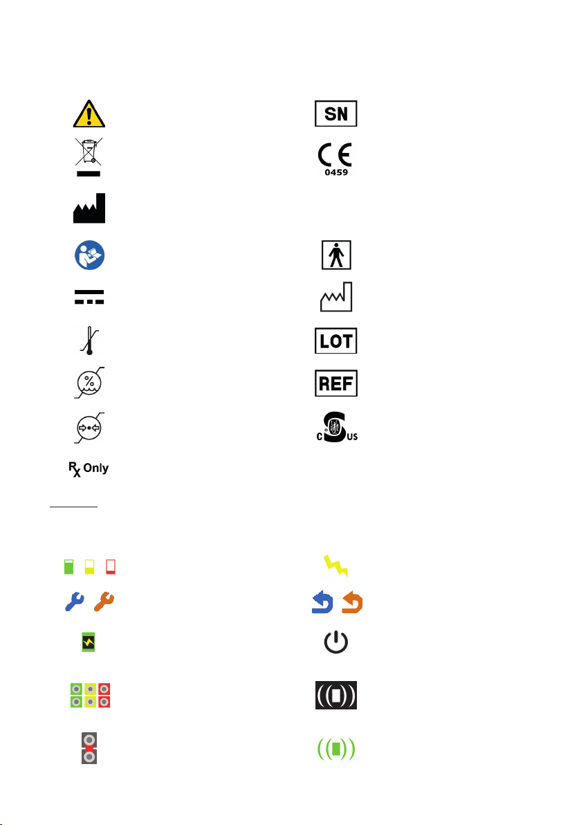
Explanation of the symbols
General symbols
Caution Serial number
Indicates a requirement for
separate treatment of
end-of-life general waste.
Labelling in compliance with
the European directive on
medical devices
Manufacturer IP 30
Protection class against solid
foreign bodies and liquids (no
protected against liquids)
Refer to the operating manual Type BF Applied Part
Direct Current DC (5V, 1A) Date of manufacture
Temperature limit Lot code
Humidity limitation Catalogue reference
Atmospheric pressure
limitation
Curtis-Straus Mark
(USA and Canada)
Prescription use device in USA
Caution: USA federal law restricts this device to sale by or on the order of an
anesthesiologist or other qualied practitioner.
Symbols displayed on the ToFscan screen
Battery level (green, yellow,
red)
Symbol for the intensity of the
stimulation current
Symbols for accessing the
conguration menu
Symbols for returning to the
main menu
Symbol for battery charge in
progress / or operation on
mains adaptor
Switch off
Impedance Level Symbol
(green=OK, yellow =medium,
red=impedance too high and
stimulation impossible)
Symbol for movement
connector not connected
(white)
Short circuit condition of
electrode cable or electrodes
(grey)
Symbol for movement
connector connected (green)

User Manual ToFscan 9
I General information
Overview of the ToFscan and its accessories
Display screen
Power supply unit
Sensor
+ electrodes cable
(thumb sensor)
Front connector for
sensor cable
Selection wheel
Main menu, Display screen
The various
stimulations
(or menu)
Stimulation
current selected
Switch off the device
Sensor cable
connection
Patient/Electrode
impedance
Battery level
Time expired since the last
selected measurement
Settings
Menu selection
The menus, options and various tests are accessed using the selection wheel on the front
of the ToFscan. The user navigates through the various menus by turning the wheel (clockwise or
anti-clockwise).
To select a menu or function, press the wheel an release the wheel button(holding it down for less
than 1 second).
To start a test or an electrical stimulation, to access the settings or switch off the device, press and
hold the wheel button for 2 seconds.
Battery / AC power supply operation
The ToFscan carries a battery enabling it to function independently on battery power for
close to 1 month (for more information refer to the battery section). This battery is recharged by the
power supply provided with ToFscan.
The power supply unit can be used as a permanent mains power supply unit. This means
that the ToFscan will operate via its mains power supply unit without necessarily running down the
battery. In this operating mode, the ToFscan displays the results and all information continuously. It

User Manual ToFscan 10
will go into energy-saving mode 2 hours after it is last used or the last measurement is taken.
When ToFscan operates on battery “ECO” mode can be activated by the user (for more information
on “ECO” mode refer to the section “Parameters Menu” “ECO”).
Note:
Position the ToFscan and the power supply in order to disconnect easily. Fully charge the
battery before the rst use.
If the power supply unit should malfunction, never use power supply units other than those
supplied by IDMED.
The ToFscan displays a power cut-off icon in the main menu. This enables the user to turn
off the device by selecting this option pressing and holding the selection wheel.
II ToFscan setup
Cable / Cable connection
The user connects the sensor+ electrode cable to the ToFscan prior to use. The user will
make sure sensor symbol is displayed in green on the right side of the screen after this cable is
connected to the ToFscan. If the operator is using a standard cable, the grey symbol should be
displayed in grey on the screen.
Electrodes
The ToFscan must be connected only to surface electrodes by “press-on” connection. The
electrodes must be electrodes used for electrical stimulation of patients. They should be compatible
with the stimulation values currently used by a NeuroMuscular Transmission Monitor and should
therefore support voltages of up to 300V and a maximum current of 60 mA. The surface areas that
come into contact with the patient should be minimal (2 cm², for example).
Positioning of the electrodes
NMT blockade may be monitored by stimulating various nerves and observing the
response of the particular muscles.
Check the availability of the sensor in your country with the authorized distributor or manufacturer.
In the case of continuous monitoring, the most commonly used technique is considered
to be stimulation of the ulnar nerve and measurement of acceleration in the adductor muscle of the
thumb.
“Thumb” sensor:
In the case of monitoring the adductor muscle of the thumb (adult or paediatric sensor), the
electrodes will be positioned along the ulnar nerve on the inner arm near the wrist. The electrodes will
be spaced 2 to 5 cm apart when using single electrodes.
Note:
It is vital to position the electrodes properly in order to stimulate the nerve and not the
muscle.
Position of the sensor and the electrodes:
Positioning of the
electrodes
(example using a double
electrode)

User Manual ToFscan 11
“Eyebrow” sensor
With the « eyebrow » sensor, it is possible to evaluate the level of blockade of the patient
while measuring the response level of the corrugator supercilli muscle.
The stimulation electrodes are to be positioned on the root of the facial nerve next to the
tragus. The positioning will be done on each side of an imaginary line going from the tragus extremity
to the middle of the nose. The distance between the electrodes will range from 2 to 5 cm.
Note:
It is essential to correctly position the electrodes in order to stimulate a nerve and not a muscle.
Electrodes positioning
to stimulate the facial nerve
“Big Toe” sensor
The stimulation electrodes are to be positioned on the tibial nerve above the ankle. The
distance between the electrodes ranges from 2 to 5 cm.
Note:
It is essential to correctly position the electrodes in order to stimulate a nerve and not a
muscle.
Placing of the sensor
When positioning the sensor, the sensor cable must not apply any pressure to the
sensor or the sensor clamp. It must allow the sensor to move freely according to muscle contractions.
Positioning the sensor in contact with the patient must not cause excessive pressure or stress that
could injure the patient.
“Thumb” sensor
The splint must follow the shape of the hand as closely as possible and be positioned so
that it makes contact with the last phalanx of the thumb.
Positioning of the
sensor splint on the
patient’s hand.
Positioning by adhesive
Paediatric ‘Thumb’
sensor

User Manual ToFscan 12
‘Eyebrow’ sensor
The positioning must allow the free movement of the sensor. The sensor is positioned on
the corrugator supercillii muscle. The sensor cable exert no tension on the sensor. The sensor is xed
with a double sided tape on the patient’s skin. This tape must be adapted to a medical usage and
allow a reliable xing during the whole duration of the monitoring.
Positioning of the ‘eyebrow sensor’
on the patient’s eyebrow
‘Big Toe’ sensor
The positioning must allow the free movement of the sensor. The sensor cable exert no
tension on the sensor. The sensor is xed with one side tape to the patient’s big toe. This tape must
be adapted to a medical usage in contact with patient’s skin. It is essential to note that the toe and
ankle of the patient must be free to move.
Position of the ‘big toe’ sensor
on the patient’s toe
Notes:
While the device is being operated, the user should check that the sensor must keep the
same position as the one from the initial set-up. The same applies for the patient’s arm, leg or head
which should not change position for the duration of the monitoring process.
If the ‘Thumb’ sensor does not t nicely the hand, it can be xed with medical adhesive tape to be
maintained in an ideal position. The user can immobilize the last three ngers with an adhesive strap
to improve the thumb range of motion and obtain more precise measure during the monitoring of
the thumb.
In the case of the thumb sensor, check that the splint part of the
sensor or the ring around the index nger does not cause pressure or excessive stress,
an adhesive positioning (see image «Positioning by adhesive») can then be put in place.
After a certain period of use of the sensor, a slight mark or redness of the skin in the
contact area with the sensor may appear. This mark or redness is due to the presence of the
sensor in contact with the skin. This must remain limited, harmless and not look like an injury.
Immobilization of the last three ngers of the hand can improve the amplitude of
thumb movement and obtain more accurate measurements when monitoring thumb movement.
Skin impedance
The ToFscan is an electrical stimulator with a constant current. Therefore, irrespective of
skin impedance it will stimulate the patient with an identical current. It will function in this way so long
as the needed voltage is below 300 V. Because of this limit you need to have a good skin impedance.
For example, to get a 60 mA current through a resistive charge the maximum impedance should
be equal to 5 Kohms. The skin impedance is more complex than a simple resistive charge and the
ToFscan will help you getting a good impedance with a colored electrodes symbol.
Only the green symbol allows to use in good condition the ToFscan. With yellow symbol the intensity
of electric stimulation may be lower than expected. If the symbol is red the ToFscan doesn’t provide
electric stimulations.

User Manual ToFscan 13
Note:
Cleaning the patient’s skin prior to positioning the electrodes signicantly lowers skin
resistance. The user should therefore ensure that the patient’s skin has been cleaned before
attaching the electrodes.
Connecting the cable to the ToFscan
After putting the electrodes on the patient, the user must connect them to the
ToFscan with the electrodes cable. Before connecting the cable, he/she should check that the ToFscan
displays the main menu and is not in stimulation phase or programmed in automatic stimulation
mode.
The proximal electrode (nearest to the heart) will be connected to the red-coloured
positive electrode clamp. The distal electrode (further away from the heart) will be connected to the
black-coloured negative electrode clamp.
Once the cable has been connected to the electrodes, the impedance level and sensor
symbols must turn green.
Reference
The “REFERENCE” mode enables the user to measure the patient’s motor response
to TOF electrical stimulation when the patient is anaesthetised but not under the effect of a
neuromuscular blocking agent. This measurement is used to display the calculation comparisons
between the range of the patient’s muscle response under curare and without curare during TOF
stimulations.
For further information about this test, refer to the “TOF mode” section, under the “REFERENCE” menu.
III Using the ToFscan
General principle
The ToFscan is used to perform 5 distinct modes of stimulation (or 5 distinct electrical
stimulations). Some of these modes can be congured or programmed by the user.
All modes are selected by a brief push on the wheel button. Once in the submenu, press and hold the
wheel button to start the electrical stimulation. The ToFscan will give a “beep” simultaneously to the
start of the electrical stimulation.
It is important to observe a time interval between each stimulation to avoid distorting the
results. The ToFscan memorises the elapsed time since the previous stimulation and displays it at
the bottom of the screen. If this time period is shorter than the interval to be observed between each
stimulation, the time to wait before the next stimulation is displayed in the centre of the screen (“Wait
X seconds”).
For example, the ToFscan requires a time interval of 12-second after each TOF stimulation.
For the modes “TOF”, “TOF AUTO”, “TOF+PTC”, “PTC” the automatically displayed measures
(percentage, number of answers) could be replaced by “---“ if electrosurgery had interfered with
the measure.
Using electrosurgery at the same time as the ToFscan can interfere with the measurement and its
results. If the results are disturbed, the ToFscan will display the symbol “---“. Then the user can do
the test again (while respecting the interval) or wait for the next test scheduled (“AUTO TOF” mode).
During those interference’s phase the impedance icon will turn red.
Note:
The recommended intervals between each stimulation are shown at the end of each
description of the various stimulations (or tests).
Only ‘TOF’ tests are commonly used for the NMT monitoring for the eyebrow muscle (stimulation of
the facial nerve).
When disconnecting the ToFscan from a patient at the end of the operation and before
connecting a new patient for new operation, the display of the ToFscan must be reset. For this, press
the wheel an release the wheel button.

User Manual ToFscan 14
TOF mode
The “TOF” menu includes 4 options or sub-menus. Each of these options is detailed
below. With this mode, the TOF stimulation can be done two ways, either directly by the operator, or
automatically at a repeated interval selected by the user.
“TOF” sub-menu
After selecting the “TOF” menu and then the “TOF” sub-menu, the user can start a “TOF”
stimulation (or test) by pressing and holding the selection wheel. Prior to this, he must verify that
the output (current in mA) of the selected stimulation is appropriate for the level of anaesthesia, the
level of neuromuscular blockade and the patient’s prole. For further information on stimulation
output, refer to the “Parameters” section.
TOF stimulation is one of the most commonly used forms of stimulation, comprising 4
stimulations (of 200 µs) at 0.5 second intervals.
If the ToFscan is connected to a cable tted with an accelerometer sensor, after the
electrical stimulation it will display a calculation of the percentage of the range of the 4th response
against the rst (ratio T4/T1 TOF as a %). If the T2 response is higher than the T1 response, the ToFscan
calculates the T4/T2 ratio rather than T4/T1.
When the ToFscan detects fewer than 4 responses (1 or 2 or 3) it displays the number of
responses.
If a “Reference” test (or stimulation) was performed, the ToFscan automatically displays the
percentage of the T4/Tref ratio.
The time interval required by the ToFscan between two “TOF” stimulations is 12 seconds.
Note:
The user should validate the results readout by pressing the selection wheel in order to
perform other stimulations. The percentage calculations are limited to 100% so that values which are
not pertinent will not be displayed.
“AUTO TOF” sub-menu
The “AUTO TOF” sub-menu is used for programming TOF stimulations at a given interval
selected by the user. The interval is chosen in the sub-menu “TOF-DELAY”. The available intervals are
every 15s., 30s., 1min., 2min., 5min. and 15min.
After selecting the stimulation interval from “TOF DELAY”, the user goes to the “AUTO TOF”
sub-menu and starts the stimulation cycle by pressing and holding the selection wheel (for at least
1 second). The rst stimulation is delivered 4 seconds after the selection wheel has been pressed.
To stop a programme, press the selection wheel; the ToFscan then returns to the “AUTO
TOF” menu.
Note:
The user can modify the stimulations interval directly (when AUTO_TOF test is gone) by
turning and pushing the button wheel.
“TOF DELAY” sub-menu
The “TOF DELAY” menu is used to select stimulation interval to be used in the “AUTO TOF”
stimulation mode. The values are selected by navigating with the selection wheel (turning it) and
then selecting the desired value by pressing the wheel.
“REFERENCE” sub-menu
The reference mode enables the user to store the patient’s response to a TOF electrical
stimulation when the patient is anaesthetised but not under the effect of neuromuscular blocking
agent. This value can help the user to evaluate the recovery of neuromuscular function and the
efciency of agent depolarizing neuromuscular blocking.
The ToFscan delivers the TOF stimulation in order to calculate the median range of the four
muscle responses; this value will be recorded as Tref. This median range will be used to calculate T4/
Tref and will be displayed for subsequent TOF stimulations.
The time interval between two “REFERENCE” stimulations is 12 seconds.

User Manual ToFscan 15
Note:
The reference test is used only to calculate T4/Tref during a TOF electrical stimulation .
Like all electrical stimulations, the stimulation used for the reference must only be
performed on anaesthetised patients. Stimulations can be very painful for non-anaesthetised
patients.
After the results are displayed, the selection wheel must be pressed to return to the
selection menu.
Reference will be valid only if the four answers have a TOF percentage of 100% and a similar
prole. Reference value can be erased by holding down wheel button more 1 second in the sub-menu
«Reference».
TET mode
Tetanic stimulation or “TETANUS” stimulation is used to stimulate a patient for 5s at 50
Hz. As the ToFscan does not display a measurement at the end of this test, no user validation is
expected at the end of the stimulation in order to reactivate the selection wheel navigation function.
The patient’s motor response is not measured by the ToFscan sensor, but is visually gauged by the
user.
Note:
The time interval required by the ToFscan between two “TET” stimulations is 3 minutes. The
“TET” stimulation is absolutely not recommended in case of the eyebrow muscle monitoring.
DBS mode
The ToFscan is used to perform “Double Burst Stimulations” or “DBS”. It offers the user
2 types of DBS mode under the “DBS MODE” menu. The DBS mode can help to detect a possible
residual blockade. DBS stimulations consist of two bursts of 50 hertz stimulations spaced 750 apart.
Depending on the selected DBS mode, each burst will have 2 or 3 impulses (impulse duration: 200
µs). In «DBS» mode, the number of detected responses is displayed along with bars to assess the
amplitude of the patient’s motor responses.
“DBS” sub-menu
The ToFscan provides “DBS 3.3” stimulation by default. The user can activate this
stimulation by pressing and holding the selection wheel, or the “DBS 3.2” stimulation after having
selected it under the “DBS Mode” menu.
“DBS MODE” sub-menu
This menu is used to select the various types of DBS stimulations. The ToFscan allows DBS
3.3 and DBS 3.2.
Note:
The time interval after a “DBS” stimulation is 20 seconds. The « DBS » stimulation is
absolutely not recommended in case of the eyebrow muscle monitoring.
PTC Mode
“PTC” or “Post Tetanic Count” stimulation is generally used for deep neuromuscular block
or when there is no response to TOF stimulation. “PTC” stimulation comprises a 5-second “TETANUS”
stimulation at 50 Hz followed by a 3-second pause and then 10 “SINGLE TWITCH” stimulations.
“PTC” sub-menu
When selecting this sub-menu, the user starts PTC stimulation by pressing and holding
the selection wheel. Upon completion of the stimulation (18 seconds’ duration) the ToFscan displays
the number of muscle responses detected. It maps out each of these in the form of a bar chart to
compare their respective ranges.
“ATP” sub-menu
ATP (Automated TOF PTC) is an automatic mode to measure deep, average and light
neuromuscular blockade using the thumb sensor only. ATP mode uses TOF and PTC stimulations in
appropriate ways. Stimulations are repeated every 30 seconds or every 5 minutes depending on the
number of responses measured after each stimulation.

User Manual ToFscan 16
Principle
ATP can be stopped at any time by the user by pushing the wheel button. ATP mode uses
TOF and PTC stimulations depending on the depth of blockade. Results are displayed as per the
stimulation applied. ATP delivers TOF stimulation at the beginning and measure the results to provide
PTC stimulation or not. In case of no response from the rst TOF stimulation, a PTC stimulation will be
applied. After all stimulations the ToFscan displays the results.
After PTC stimulations, there is a pause of 5 minutes before the next set of stimulations, but only 30
seconds in case of TOF stimulations. For more information about ATP mode check the process below.
ATP Process
IDMED 20/07/2017 V4 CONFIDENTIAL / USAGE INTERNE A IDMED
ATP Mode
*Condition 1: One response or more at TOF ?
*Condition 2 : 4 responses have been measured at previous TOF stimulation ?
TOF Stimulation
Pause 30s.
Pause
5mn.
Yes
No
Displaying
TOF results
Displaying
PTC results
Condition
2*
Pause
2s
PTC Stimulation
Yes
ATP start
ATP
stop
Condition
1*
No
Moderate
NeuroMuscular Block
Deep
NeuroMuscular Block
*Condition 1: One response or more to TOF ?
* Condition 2: 4 responses have been measured at previous loop for TOF stimulation?
Note:
The interval required by the ToFscan following “PTC” stimulation is 3 minutes. It is important
to remember that “PTC” and “ATP” stimulations are only normally used when no responses to “Single
Twitch” or “TOF” stimulations are detected. ”PTC” and “ATP” mode must only be used with the thumb
sensor and only with non-depolarizing neuromuscular blocking agents.
ATP mode can be stopped at any time by pushing the wheel button.
ST Mode
This is the simplest form of stimulation producing a single muscle contraction. The
patient’s motor response is not measured by the ToFscan sensor but is visually gauged by the user.
“Twitch” sub-menu
Stimulation is activated by pressing (2s) the selection wheel.
“0.1HZ” sub-menu
The ToFscan produces one twitch every 10 seconds when the selection wheel is pressed
and held. The user stops the 0.1 HZ stimulation by simply pressing the selection wheel.
“1HZ” sub-menu
The ToFscan produces one twitch every second when the selection wheel is pressed and
held. The user stops the 1 HZ stimulation by simply pressing the selection wheel.
Note:
The “0.1 HZ” or “1 HZ” stimulations are automatically repeated during 10 minutes, after which

User Manual ToFscan 17
the ToFscan stops the stimulation. No time interval is necessary between each “twitch” stimulation.
No waiting period is required by the ToFscan after this category of stimulations. The practitioner will
gauge the length of the waiting period required depending on the number of stimulations delivered.
Parameters Menu
The “Parameters” menu will enable the user to modify the standard parameters of the
ToFscan. This menu is represented on the screen by the following icon:
To go to the “Conguration” menu, the selection wheel must be pressed and held (2s).
“STIM” sub-menu
When this sub-menu is selected by pressing the selection wheel, the user can
adjust the current of the stimulations. The ToFscan is congured to 50 mA by default. It is
generally acknowledged that in order to obtain supra-maximal stimulation, the current required for the
stimulation of the Ulnar or tibial nerve for the adult is 50mA. This value is 30mA for a
paediatric usage on the same nerves. The value for the stimulation in the case of the eyebrow
muscle (Corrugator Supercilli) is 30mA. In special cases where considered appropriate by the
user, he/she may adjust this stimulation value. The user should consider the potential risks of an
unsuitable stimulation current for a patient.
“Language” sub-menu
The language sub-menu is for selecting the language of the displayed text in the ToFscan.
“SND” sub-menu
The SND sub-menu allows activating or inactivating the sound “beep” of validation/
selection.
“ECO” sub-menu
The ECO sub-menu allows selecting the eco mode. “ECO” mode reduces the length of
display to increase the time life of battery if the ToFscan is not connected to the power supply. If it is
connected the display becomes inactive 6s after the last automatic measure and 40s after the last
manual measure.
IV Servicing, Disinfection cleaning
Preventive servicing, Maintenance
In order to maintain its performance, it is strongly recommended that the following tests be carried
out on the device at least once every two years:
• checking of the integrity of the casing, screen and labelling
• checking of the battery charging process
• checking of the condition of the electrode cable, its electrode clamp ends and its sensor clamp
• checking for the value of current of electrical stimulations.
• checking the sensor measures.
Caution:
Only qualied technicians are authorised to carry out some repairs with the consent of IDMED.
Certain repairs or maintenance operations can be only done by IDMED.
User Manual ToFscan 18
Battery / Battery charge
Battery
The ToFscan includes a Lithium-Ion rechargeable battery. The battery is equipped with
thermal protection and short-circuits protection. At full charge, battery power lasts for approximately
1 month at a rate of 10 “TOF” stimulations per day (“Eco” mode activated).
Level and colour gauges indicates the level of charge of the battery
Battery level (green, yellow, red)
The battery has a one-year warranty (its battery power at one year should be 50% more than its
estimated battery power). The normal service life of the battery is 2 years.
Note :
Only qualied technicians are authorised to carry out repairs or maintenance operations
with the consent of IDMED.
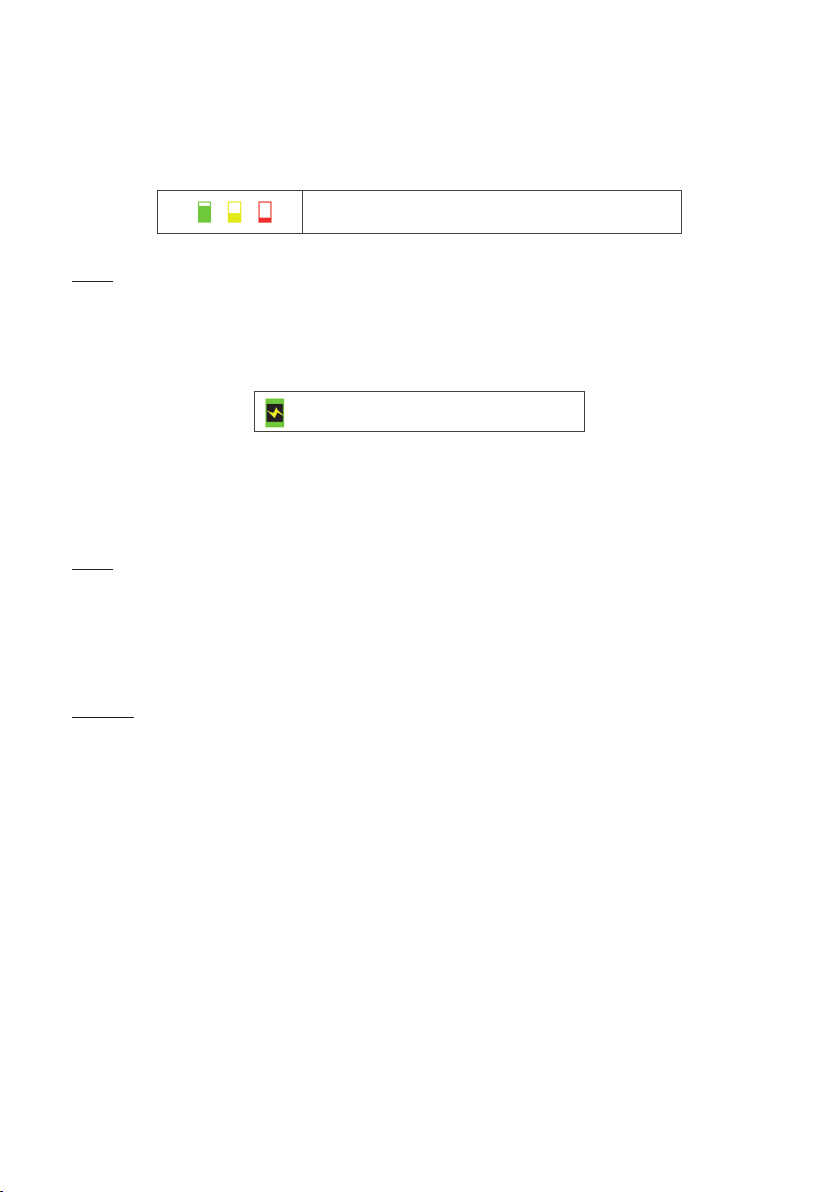
Battery Charge
The battery is charged with the charger supplied by IDMED. It can charge a at battery in
less than 8 hours.
Icon for battery charge in progress or icon
for operation on the AC power adaptor
The battery can be charged regardless of its level. Whenever the ToFscan displays the at
battery symbol (coloured red), the battery must be charged as soon as possible.
Charging is automatic, consequently when the charge is complete the ToFscan stops the
process.
Note :
Only qualied technicians or IDMED employees are authorized to carry out repairs or
maintenance operations on the battery.
Maintenance work on the battery is restricted to checking its charge cycle once a year. By
doing this, it can be veried that the charge cycle does not exceed 8 hours (a change from red to
green for the battery charge gauge).
Cleaning
Caution:
Do not place the ToFscan or any of its parts or accessories inside an autoclave.
Under no circumstances must the ToFscan or any of its parts or accessories come into direct
contact with, be immersed in or lled with liquid.
The ToFscan and its parts and accessories are non-sterile devices. Under no circumstances must the
ToFscan or any of its accessories be sterilized.
The surfaces of the ToFscan and its accessories have to be cleaned with a lint-free cloth moistened
with a Quaternary Ammonium Compound (QACs), isopropyl alcohol 70%. Before using any of these
solutions, refer to the manufacturer’s documentation and test on a reduced surface.
Example of recommended Quaternary Ammonium product:
- mikrozid®sensitive liquid from the manufacturer Schülke & Mayr GmbH.
Please check with your local authorized distributor or with the manufacturer which products are
available and approved in your country.
The ToFscan cable (electrode and/or sensor) must not come into direct contact with, be
immersed in, splashed or lled with liquid and is to be cleaned in the same manner as the
ToFscan.
When cleaning the calbles of the ToFscan, be careful not to create excessive traction on the splint
that could cause premature breakage of the wires inside the sheath.

User Manual ToFscan 19
Diagnostic / Malfunction
The table below summarises a list of possible malfunctions and the solutions for resolving them.
Malfunction Solution
The device does not start or stops on its own
after a few seconds (Message “Low Battery”)
Set the device to charge (refer to the section
“Battery and battery charge”)
The sensor icon is displayed in grey even though
the sensor is connected.
Check the condition of the cable and the sen-
sor. Disconnect the cable and reconnect to the
ToFscan
The ToFscan displays the impedance value in
red (impedance too high)
Check the positioning of the electrodes and
how they couple with the patient (refer to the
section “Connection and positioning of stimula-
tion electrodes”).
Note:
Should the problem persists or is not solved by the actions listed in the table above, you
must contact the distributor. .
V End-of-life disposal / Recycling
In the interest of environmental safety, you are required to pass your used system on to a
collection body with the capability to treat devices containing electronic components and
Lithium-ion storage batteries.
To dispose of or recycle device components, contact a company specialising in the recycling of
electronic devices.
Unsorted electronic waste products are potentially hazardous to the environment.
Packaging materials must be disposed of or recycled in accordance with the regulations in force.
VI Technical specications and warranty
The ToFscan comes with a microcontroller and a colour LCD screen for optimal legibility and ease
of use.
Safety
• Biocompatible material sensors (part in contact with the patient). Latex free
• Compliant with European directive CEE 93/42. Class 2a device (CE 0459 LNE/G-MED)
• Compliant with standards IEC 60601-1. Class II equipment.
• Compliant with standards IEC 60601-2-10.
• EMC: IEC 60601-1-2
EMC Emission
Emission test Compliance EMC Instructions/cautions
RF Emissions CISPR 11 Group 1 The ToFscan uses RF energy only for internal func-
tions. Therefore RF emissions are very low and
should not disturb other nearby devices.
RF Emissions CISPR 11
Harmonics IEC 61000-3-2 Class B The ToFscan must be use in professional healthcare
facility environment
Voltage uctuations Class A
and icker IEC 61000-3-3 Compliant The ToFscan can be connected to the public mains
network

User Manual ToFscan 20
EMC Immunity
Phenomenon Basic EMC
standard
Professional
healthcare
facility
environment
Immunity Test
Levels
Compliance
levels EMC
Instructions/precautions
ELECTROSTATIC
DISCHARGE
(ESD)
IEC
61000-4-2
± 8 kV contact ± 8 kV contact In order to reduce ESD, the device
must be used in a 35% humidity envi-
ronment or more
± 2 kV, ± 4 kV,
± 8 kV,
± 15 kV air
± 2 kV, ± 4 kV,
± 8 kV air
Radiated RF EM
Fields IEC
61000-4-3
3 V/m
80 MHz – 2,7
GHz
80 % AM at
1 kHz
3 V/m
80 MHz – 2,7
GHz
80 % AM at
1 kHz
Use of this equipment adjacent to or
stacked with other equipment should
be avoided because it could result in
improper operation. If such use is ne-
cessary, this equipment and the other
equipment should be observed to ve-
rify that they are operating normally
Proximity elds
from RF
wireless com-
munications
equipment
IEC
61000-4-3
Complies to
table 9 of IEC
60601-1-2
(2014)
Complies to
table 9 of IEC
60601-1-2
(2014)
In order to prevent electromagnetic
disturbance, keep minimum separa-
tion from RF communication equip-
ment of 30cm
Electrical fast
transients /
bursts
IEC
61000-4-4
± 2 kV
100 kHz
repetition
frequency
± 2 kV
100 kHz
repetition
frequency
The ToFscan may temporarily not dis-
play result during transient electro-
magnetic disturbances such as the
use of electrosurgery device. In that
case, the ToFscan will maintain the
safety of the patient and the user.
Surges
Line-to-line IEC
61000-4-5 ± 0,5 kV, ± 1 kV ± 0,5 kV, ± 1 kV Mains power quality should be that of
a typical residential, commercial or
hospital environment.
Surges
Line-to-ground IEC
61000-4-5
± 0,5 kV, ±
1 kV,
± 2 kV
± 0,5 kV, ± 1
kV, ± 2 kV
Mains power quality should be that of
a typical residential, commercial or
hospital environment.
Conducted
disturbances
induced by RF
elds
IEC
61000-4-6
3 V
0,15 MHz –
80 MHz
6 V in ISM
bands
between 0,15
MHz and
80 MHz
80 % AM at
1 kHz
3 V
0,15 MHz –
80 MHz
6 V in ISM
bands
between 0,15
MHz and
80 MHz
80 % AM at
1 kHz
In order to prevent electromagnetic
disturbance, keep minimum separa-
tion from RF communication equip-
ment of 30cm
RATED power
frequency
magnetic elds
IEC
61000-4-8 30 A/m
50 Hz or 60 Hz 30 A/m
50 Hz or 60 Hz
Mains power quality should be that of
a typical residential, commercial or
hospital environment
Other manuals for ToFscan
4
Table of contents
Other Idmed Medical Equipment manuals


Popular Medical Equipment manuals by other brands


Getinge
Getinge Arjohuntleigh Nimbus 3 Professional Instructions for use

Mettler Electronics
Mettler Electronics Sonicator 730 Maintenance manual

Pressalit Care
Pressalit Care R1100 Mounting instruction

Denas MS
Denas MS DENAS-T operating manual

bort medical
bort medical ActiveColor quick guide

AccuVein
AccuVein AV400 user manual


