IDT ZMID520 Series User manual

ZMID520x Evaluation Kit User Manual
© 2018 Integrated Device Technology, Inc.
1
September 25, 2018
Description
The ZMID520x Evaluation Kit enables evaluation of the IDT
ZMID520x Family of Inductive Position Sensor ICs via IDT’s
ZMID520x Application Modules (available separately). It can be
used for the sensor calibration for the following ICs:
ZMID5201: analog interface
ZMID5202: PWM interface
ZMID5203: SENT interface
The main purpose of the ZMID520x Evaluation Kit is communica-
tion between the user’s computer and the ZMID520x. The user’s
computer sends commands and data via its USB port to the ZMID
Communication Board (ZMID-COMBOARD).
The microcontroller on the ZMID-COMBOARD interprets these
commands and relays them to the ZMID520x located on the
ZMID520x Application Module using the one-wire interface (OWI)
communication interface.
The microcontroller also forwards data bytes from the ZMID520x
back to the computer via the USB connection. These bytes can be
sensor readings, ZMID520x internal registers values, or ZMID520x
EEPROM contents.
The ZMID520x EVKIT Application Software is a graphical user
interface (GUI) that is provided online for the kit. It supports all
ZMID520x configurations and enables the user to understand the
functionality of the ZMID520x as well as perform measurements.
Features
USB “plug and play”–no driver installation needed
Small ZMID-COMBOARD: 4cm 7.3cm
One-wire communication interface (OWI) enables quick and
easy configuration and calibration of the ZMID520x using the
user’s computer
PWM, analog, or SENT reading of the output depending on
product code
The modular design allows easy swapping in different
ZMID520x Application Modules (available separately) for
evaluation using the same ZMID-COMBOARD and ZMID520x
EVKIT Application Software
The kit software is available for download from the IDT
product page for the ZMID-COMBOARD:
www.IDT.com/ZMID-COMBOARD
Kit Contents
ZMID-COMBOARD
Micro-USB cable
Figure 1. ZMID520x Evaluation Kit and ZMID520x Application Modules

ZMID520x Evaluation Kit User Manual
© 2018 Integrated Device Technology, Inc.
2
September 25, 2018
Important Notes
Disclaimer
Integrated Device Technology, Inc. and its affiliated companies (herein referred to as “IDT”) shall not be liable for any damages arising out of defects resulting from
(i) delivered hardware or software
(ii) non-observance of instructions contained in this manual and in any other documentation provided to user, or
(iii) misuse, abuse, use under abnormal conditions, or alteration by anyone other than IDT.
TO THE EXTENT PERMITTED BY LAW, IDT HEREBY EXPRESSLY DISCLAIMS AND USER EXPRESSLY WAIVES ANY AND ALL WARRANTIES, WHETHER
EXPRESS, IMPLIED, OR STATUTORY, INCLUDING, WITHOUT LIMITATION, IMPLIED WARRANTIES OF MERCHANTABILITY AND OF FITNESS FOR A
PARTICULAR PURPOSE, STATUTORY WARRANTY OF NON-INFRINGEMENT, AND ANY OTHER WARRANTY THAT MAY ARISE BY REASON OF USAGE
OF TRADE, CUSTOM, OR COURSE OF DEALING.
Restrictions in Use
IDT’s ZMID520x Evaluation Kit, consisting of the ZMID-COMBOARD and micro-USB cable used in combination with the ZMID520x Application Module and the
ZMID520x AID EVKIT Application Software, is designed for evaluation and configuration of the ZMID520x product family only. IDT’s ZMID520x Evaluation Kit
hardware and software must not be used for characterization measurements in terms of replacing calibrated laboratory environment and measurement devices.
Important Safety Warning: These procedures can result in high currents, which can cause severe injury or death
and/or equipment damage. Only trained professional staff should connect external equipment and operate the software.
Important Equipment Warning: Ensure the correct connection of all cables. Supplying the board using the wrong
polarity could result in damage to the board and/or the equipment.
Contents
1. Setup ............................................................................................................................................................................................................5
1.1 Required User Equipment ...................................................................................................................................................................5
1.2 User Computer Requirements and Setup ...........................................................................................................................................5
1.2.1 Computer Requirements ......................................................................................................................................................5
1.2.2 Software Installation and Setup............................................................................................................................................5
1.3 Hardware Setup...................................................................................................................................................................................6
1.3.1 Overview of the Hardware ....................................................................................................................................................6
1.3.2 Connecting the Kit ................................................................................................................................................................9
2. ZMID520x EVKIT Application Software User Guide...................................................................................................................................10
2.1 Sections of the Display ......................................................................................................................................................................10
2.2 Getting Started ..................................................................................................................................................................................11
2.2.1 Connecting to a Device ......................................................................................................................................................11
2.2.2 Reading Measurements .....................................................................................................................................................13
!
!

ZMID520x Evaluation Kit User Manual
© 2018 Integrated Device Technology, Inc.
3
September 25, 2018
2.3 Changing the Configuration Settings.................................................................................................................................................16
2.4 Calibration .........................................................................................................................................................................................18
2.4.1 “COIL OFFSET” Sub-tab ....................................................................................................................................................18
2.4.2 “OUTPUT RANGE” Sub-tab ...............................................................................................................................................21
2.4.3 “CALIBRATION AND LINEARIZATION” Tab .....................................................................................................................26
2.5 Working with the Memory ..................................................................................................................................................................31
2.5.1 “MEMORY EDIT” Tab.........................................................................................................................................................31
2.5.2 Saving and Loading Memory Dump Files...........................................................................................................................32
2.5.3 Viewing Memory Dump Files without Connecting to a Device (Offline)..............................................................................33
2.6 Manually Identifying a Device............................................................................................................................................................34
2.6.1 Identifying an Unknown Device ..........................................................................................................................................34
2.6.2 Re-identifying a Device.......................................................................................................................................................35
3. Firmware Update........................................................................................................................................................................................36
4. ZMID-COMBOARD Schematics.................................................................................................................................................................37
5. ZMID-COMBOARD BOM ...........................................................................................................................................................................40
6. Sensors Boards..........................................................................................................................................................................................42
7. Glossary .....................................................................................................................................................................................................42
8. Ordering Information...................................................................................................................................................................................42
9. Revision History..........................................................................................................................................................................................43
List of Figures
Figure 1. ZMID520x Evaluation Kit and ZMID520x Application Modules ...........................................................................................................1
Figure 2. ZMID520x Evaluation Kit Connections –ZMID520x Arc Application Module Example.......................................................................6
Figure 3. ZMID-COMBOARD –Overview ..........................................................................................................................................................7
Figure 4. ZMID520x Rotary 360° Application Module –Overview .....................................................................................................................8
Figure 5. ZMID520x Arc 130°Application Module –Overview............................................................................................................................8
Figure 6. ZMID520x Linear Application Module –Overview...............................................................................................................................9
Figure 7. Sections of the GUI Display –Example ZMID5203...........................................................................................................................10
Figure 8. Start-up Screen .................................................................................................................................................................................11
Figure 9. Display When Connected to a Device –ZMID5203 Example ...........................................................................................................12
Figure 10. Display When Connected to 2 Devices –ZMID5203 Example..........................................................................................................12
Figure 11. “OUTPUT” Tab – ZMID5203 Example...............................................................................................................................................14
Figure 12. “INTERNAL VALUES” Tab – ZMID5203 Example ............................................................................................................................14
Figure 13. “SENT” Tab (ZMID5203 only)............................................................................................................................................................15
Figure 14. "CONFIGURE" Tab –Selection of Memory Type to be Displayed....................................................................................................16
Figure 15. Buttons in the “I/O FUNCTIONS” Section..........................................................................................................................................16
Figure 16. Options on the “SETTINGS” Menu....................................................................................................................................................17
Figure 17. Example of Numerical Values That Can be Edited............................................................................................................................17
Figure 18. Example of a Drop-Down Menu with Multiple Choice Values............................................................................................................17

ZMID520x Evaluation Kit User Manual
© 2018 Integrated Device Technology, Inc.
4
September 25, 2018
Figure 19. Example of Read-Only Values ..........................................................................................................................................................17
Figure 20. Example of a Modified Value that is Not Yet Saved to Memory ........................................................................................................17
Figure 21. Example of Tooltip Information..........................................................................................................................................................17
Figure 22. “COIL OFFSET” Tab – ZMID5203 Example......................................................................................................................................18
Figure 23. Receiver Coil (ABS Value) Offset Example with Offset Compensation =
/2..................................................................................19
Figure 24. Coil Offset Calibration Completed –ZMID5203 Example..................................................................................................................20
Figure 25. “OUTPUT RANGE” Tab – ZMID5201 Example.................................................................................................................................21
Figure 26. Linear Output Mode Example with Slope = 2, Offset = 90°...............................................................................................................22
Figure 27. Modulus Output Example with Slope = 2, Offset = 60° .....................................................................................................................22
Figure 28. Output without Clamping ...................................................................................................................................................................23
Figure 29. Output Clamped from 20% to 80%....................................................................................................................................................23
Figure 30. Specify the Original Slope .................................................................................................................................................................24
Figure 31. Request for Changing the Out_Mod Setting......................................................................................................................................24
Figure 32. Successful Calibration Message .......................................................................................................................................................24
Figure 33. Unsuccessful Calibration Message ...................................................................................................................................................25
Figure 34. "AUTO CAL" Sub-tab –ZMID5201 Example.....................................................................................................................................26
Figure 35. Example Contents of an Input .csv file with Spatial Angle Data ........................................................................................................27
Figure 36. Example Contents of a .csv Input File with Output Voltage Data ......................................................................................................27
Figure 37. Example of AUTO CAL Error Messages ............................................................................................................................................28
Figure 38. “MANUAL LINEARIZATION” Sub-tab –ZMID5201 Example............................................................................................................29
Figure 39. Calibration Diagram...........................................................................................................................................................................30
Figure 40. “MEMORY EDIT” Tab Contents – ZMID5201 Example.....................................................................................................................31
Figure 41. Example of a Modified Value on the “MEMORY EDIT” Tab..............................................................................................................31
Figure 42. Example of “MEMORY EDIT” Tab Tooltip Information......................................................................................................................32
Figure 43. Menu Options for Saving and Loading Memory Dump Files .............................................................................................................32
Figure 44. Viewing a Memory Dump File "Offline"..............................................................................................................................................33
Figure 45. GUI View if an Unknown Device is Selected .....................................................................................................................................34
Figure 46. File Dialog to Select an Identification File..........................................................................................................................................34
Figure 47. “Identify Selected Device” Menu Option ............................................................................................................................................35
List of Tables
Table 1. ZMID-COMMBOARD Key Components and Connector Descriptions.................................................................................................7
Table 2. ZMID520x Application Module: Key Components and Connector Descriptions..................................................................................8
Table 3. Bill of Materials for ZMID-COMBOARD Rev. 5.1...............................................................................................................................40

ZMID520x Evaluation Kit User Manual
© 2018 Integrated Device Technology, Inc.
5
September 25, 2018
1. Setup
1.1 Required User Equipment
A Windows®-based computer is required for interfacing with the kit and configuring the ZMID520x.
1.2 User Computer Requirements and Setup
1.2.1 Computer Requirements
The user must have administrative rights on the computer to download and install the ZMID520x EVKIT Application Software for the kit.
The computer must meet the following requirements:
Windows® Vista SP1 or later, 7 (including SP1), 8, 8.1, or 10.
Note: Touch screens are not supported.
Note: Windows® XP is no longer supported. Contact IDT for assistance. See contact information on the last page.
Supported architecture: x86 and x64.
Available USB port.
Internet access for downloading the ZMID520x EVKIT Application Software.
Microsoft® .NET Framework 4.0
1.2.2 Software Installation and Setup
The ZMID520x EVKIT Application Software is not included with the kit. To ensure use of the latest version of the software, it is available for
download free of cost in zip file format from the IDT web site on the web page given on page 1.
Follow these procedures to install the ZMID520x EVKIT Application Software:
1. After downloading the zip file to the user’s computer, extract the contents of the zip file.
2. Double-click on the extracted setup.exe file to activate the installation.
3. Follow the standard installation instructions displayed on the screen and change the installation path if required. If the default path settings
have been used, the software automatically completes the installation and creates an access link on the user’s computer under Start > All
Programs > IDT > ZMID520x EVKIT. The installation dialog offers the option to create a desktop short-cut icon for the software.

ZMID520x Evaluation Kit User Manual
© 2018 Integrated Device Technology, Inc.
6
September 25, 2018
1.3 Hardware Setup
This section describes the basic hardware setup of the ZMID520x Evaluation Kit boards and provides a brief overview on the components.
Refer to the user manual for the specific ZMID520x Application Module for the setup required for the target holder, which is shown in Figure 1,
and for further details for the module such as schematics and BOMs. The application module user manuals are available on the IDT product
web pages for the modules: See section 6 for the IDT product web pages for the application modules to download the manuals.
1.3.1 Overview of the Hardware
Figure 2 shows the board connections for the ZMID520x Evaluation Kit using the ZMID5201 Arc Application Module (ZMID520xMARC18001)
as an example.
Figure 2. ZMID520x Evaluation Kit Connections –ZMID520x Arc Application Module Example
ZMID520x Evaluation Kit User Manual
© 2018 Integrated Device Technology, Inc.
7
September 25, 2018
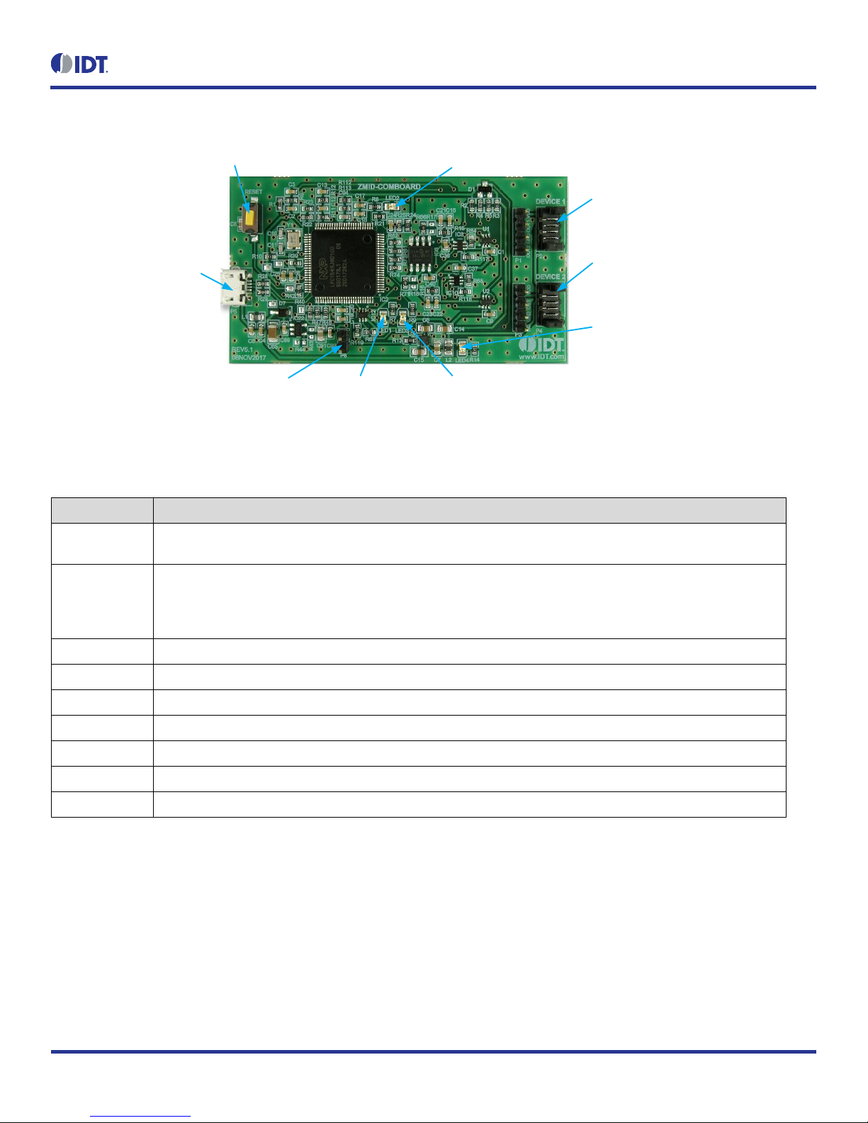
Figure 3. ZMID-COMBOARD –Overview
P5 Micro-USB Connector:
Connect to User s Computer
Reset Button
P2: Connect to Application Module
Sensor Board Via Flat Cable
P4: Connect to Optional Additional Application
Module Sensor Board Via Flat Cable
P8 Boot Pins LED1 (Red):
Fault Indicator
LED2 (Green): Information LED Indicator for Normal Operation Status
LED3 (Blue): Information LED Indicator for
Initialization or Communication
LED4 (Red): Board Power Indicator
Table 1. ZMID-COMMBOARD Key Components and Connector Descriptions
Note: See Figure 3 for the components referenced in this table.
Label
Description
P2
Connector to the ZMID520x Application Module Sensor Board. Note: The same signals are on the adjacent 4-pin header
P1, which has silkscreen labels for the pin signals: NC (no connection), GND, OUT, and VDD.
P4
Alternative connection for the ZMID520x Application Module Sensor Board instead of P2 or for an optional connection
for a second Application Module Sensor Board. If connecting to two modules at the same time, the ZMID520x ICs on the
modules must have the same output option (e.g., 2 x ZMID5201). Note that the same signals are available on the
adjacent 4-pin header P3, which has labels for the pin signals: NC (no connection), GND, OUT, and VDD.
P5
USB connector to the host PC.
P8
Boot pins.
Reset
Reset board button.
LED1 (Red)
Fault indicator LED: ON indicates an error.
LED2 (Green)
Information LED: ON indicates normal operational status.
LED3 (Blue)
Information LED: ON indicates initialization/communication.
LED4 (Red)
Board power indicator.
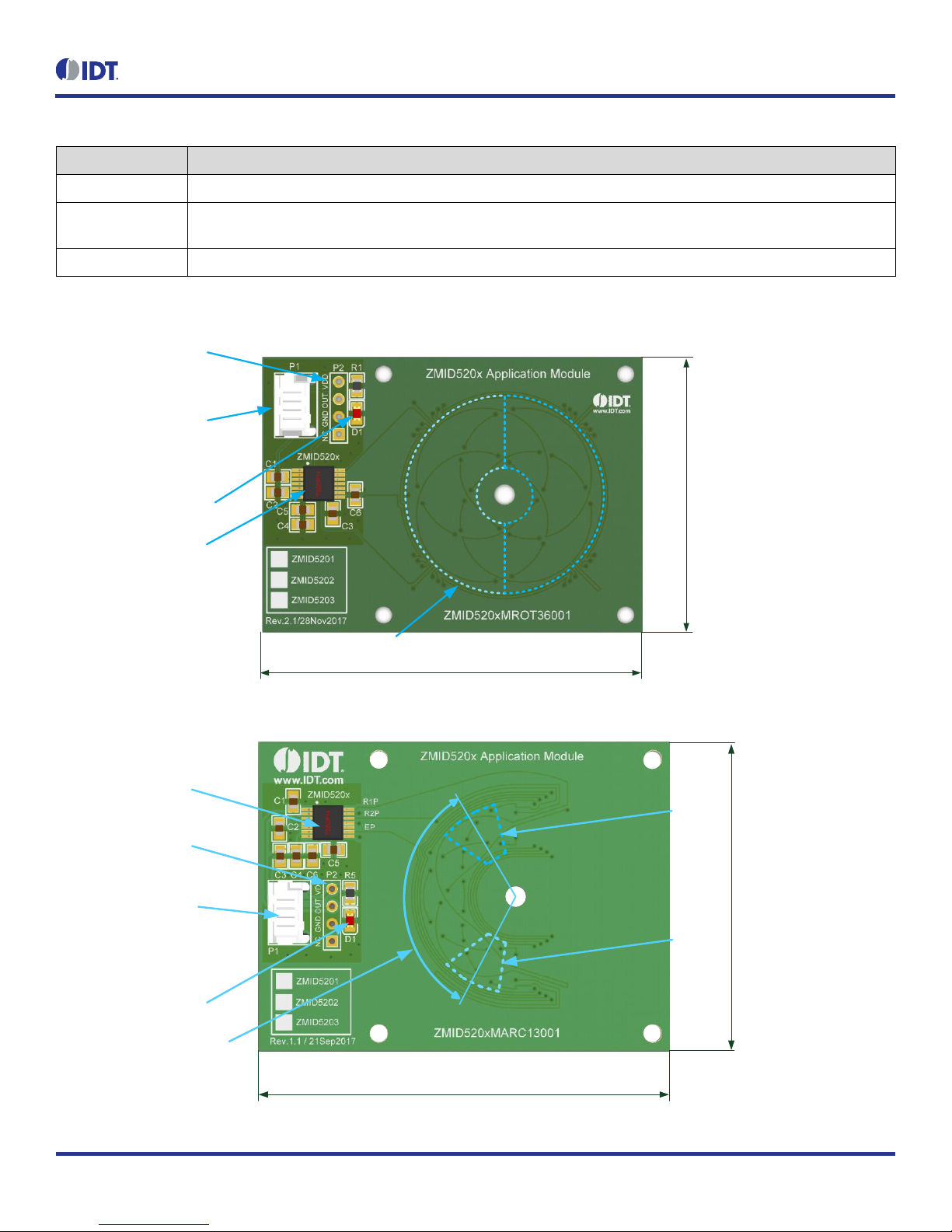
Figure 4, Figure 5, and Figure 6 give an overview of the different ZMID520x Application Module Sensor Boards before installation of the target
holder for each type of board. The three boards have the same connectors and components given in Table 2 and identified in the figures. Each
board has a silkscreen checkbox that indicates which ZMID520x IC is mounted on the Application Module Sensor Board: ZMID5201, ZMID5202,
or ZMID5203, depending on the order code for the module.
ZMID520x Evaluation Kit User Manual
© 2018 Integrated Device Technology, Inc.
8
September 25, 2018
Table 2. ZMID520x Application Module: Key Components and Connector Descriptions
Label
Description
P1
4-pin Molex Picoflex header for cable to the ZMID-COMBOARD.
P2
PCB 4-pin header for de-bugging purposes. If the user’s microcontroller is used instead of the ZMID-COMBOARD, P2 can
be used to connect the microcontroller to the Application Module.
D1
Power Indicator LED for the VDD.
Figure 4. ZMID520x Rotary 360° Application Module –Overview
ZMID520x Sensor IC
P1 Application Module
Connector for the
ZMID-COMBOARD
P2 Application Module
Interface Header for
Troubleshooting Purposes
D1 Power Indicator LED
Measurement Range: 360°
Coil Range: 360°
Target: 180° (50%)
35mm
55mm
Target Positions
Figure 5. ZMID520x Arc 130°Application Module –Overview
ZMID520x Sensor IC
P1 Application Module
Connector for the
ZMID-COMBOARD
P2 Application Module
Interface Header for
Troubleshooting Purposes
D1 Power Indicator LED
Measurement Range: 130°
Coil Range: 180°
Target: 40° (22%)
45mm
60mm
Max.
Target
Position
Max.
Target
Position

ZMID520x Evaluation Kit User Manual
© 2018 Integrated Device Technology, Inc.
9
September 25, 2018
Figure 6. ZMID520x Linear Application Module –Overview
ZMID520x
Sensor IC
P1 Application
Module Connector for
ZMID-COMBOARD
P2 Application Module Interface
Header for Troubleshooting Purposes D1 Power Indicator LED
Measurement Range
12mm (50% Target)
30mm
75mm Target Positions
1.3.2 Connecting the Kit
Important Equipment Warning: Ensure the correct connection of all cables. Supplying the board using the wrong
polarity could result in damage to the board and/or the equipment.
1. Ensure that the ZMID-COMBOARD is not connected to the computer.
2. Assemble the ZMID520x Application Module with the target holder as described in the user manual for the specific application module.
3. Connect the ZMID520x Application Module via the flat cable to the ZMID-COMBOARD as shown in the example for the ZMID520x
Arc Application Module in Figure 2. See Figure 1 for the connections for the ZMID520x Linear Application Module and ZMID520x
Rotary Application Module.
4. Connect the ZMID-COMBOARD to the computer using the micro-USB cable provided in the ZMID-COMBOARD. Power is provided
from the computer via the USB connection. No external power source is required.
5. The indicator LED2 on the ZMID-COMBOARD will light (see Figure 3) if conditions are normal. This indicates that the board is ready
to communicate with the ZMID520x EVKIT Application Software. The D1 LED on the ZMID520x Application Module (see Figure 4,
Figure 5, or Figure 6) also lights when the board is powered on.
!
ZMID520x Evaluation Kit User Manual
© 2018 Integrated Device Technology, Inc.
10
September 25, 2018
2. ZMID520x EVKIT Application Software User Guide
2.1 Sections of the Display
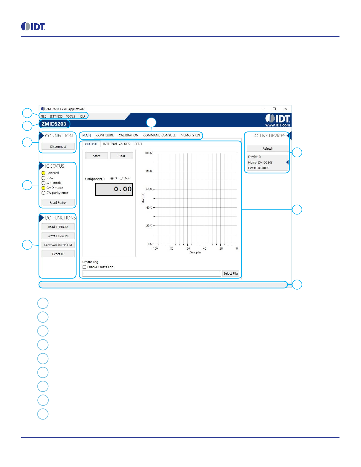
The ZMID520x EVKIT Application Software provides a graphic user interface (GUI) for communicating with the kit. The GUI is displayed when
the application is started. Figure 7 identifies the various sections of the display.
Figure 7. Sections of the GUI Display –Example ZMID5203
1
5
4
7
8
6
3
2
9
Menu bar: Contains settings and tools.
Information label: Displays the name of the connected device.
“CONNECTION” section: Displays connection-related options.
“IC STATUS” section: Displays status information from the connected device.
“I/O FUNCTIONS” section: Displays options to perform READ and WRITE actions on the connected device.
Navigation tabs: Used to switch between the different main window tabs.
“ACTIVE DEVICES” section: Displays a list of the currently connected communication boards.
Main window area: Displays options and information about the connected device.
Status bar: Displays status messages during operation.
1
2
3
4
5
6
7
8
9
ZMID520x Evaluation Kit User Manual
© 2018 Integrated Device Technology, Inc.
11
September 25, 2018
2.2 Getting Started
The following steps describe how to establish a connection to the ZMID520x Application Module and perform measurements. The combination
of a ZMID-COMBOARD and its connected ZMID520x Application Module is referred to as the “device”in the GUI.
2.2.1 Connecting to a Device
1. Ensure that the ZMID520x Application Module is properly connected to the ZMID-COMBOARD. See section 1.3.2.
2. Connect the ZMID-COMBOARD to the user’s computer using the micro-USB cable provided in the kit.
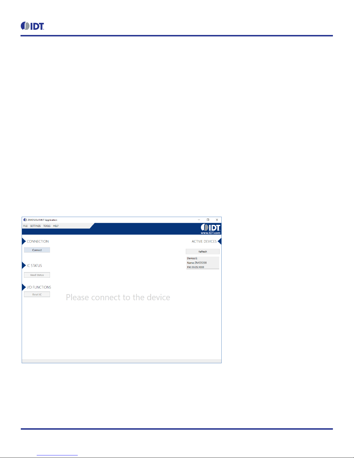
3. Start the GUI application. See Figure 8 for the start-up screen.
4. The device will appear in the “Active Devices” section. If there are no other devices on the list, it will be automatically selected;
otherwise select it by clicking on it.
5. If the device shows as unknown, manually identify the device first. For a description of how to manually identify a device, refer to
section 2.6.
6. Click on the “Connect” button to initialize the connection.
7. After a successful connection, the GUI will display the contents of the main window area.
8. Two sensor boards can also be connected to the ZMID-COMBOARD at the same time; see Figure 10 for an example. Data are
displayed according to the selection made through the drop down menu on the top left side (Module 1 or Module 2). When connecting
to two modules at the same time, both ZMID520x ICs on the modules must have the same output option (e.g., 2 x ZMID5201).
Figure 8. Start-up Screen
ZMID520x Evaluation Kit User Manual
© 2018 Integrated Device Technology, Inc.
12
September 25, 2018
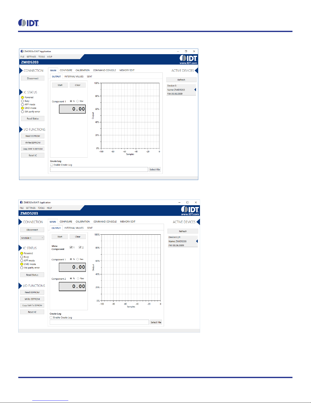
Figure 9. Display When Connected to a Device –ZMID5203 Example
Figure 10. Display When Connected to 2 Devices –ZMID5203 Example

ZMID520x Evaluation Kit User Manual
© 2018 Integrated Device Technology, Inc.
13
September 25, 2018
2.2.2 Reading Measurements
1. After connecting to a device, select the “MAIN” tab from the navigation menu. Two sub-tabs “OUTPUT” and “INTERNAL VALUES”
are displayed. For the ZMID5203, the “SENT” sub-tab is also displayed and provides a SENT interface decoder. The “OUTPUT”tab
displays the reading at the ZMID520x output pin SOUT.
2. The readings can be displayed as scaled values in percent or as raw (decimal/hexadecimal) values. Use the “Component 1” radio
buttons (“%” or “Raw”) to select the desired method for presenting the values. If there are two devices, repeat the selection for the
second device using the “Component 2” radio buttons.
The “OUTPUT” tab readings in percent represent
a. Analog values for the ZMID5201 –Percent of VDD
b. PWM values for the ZMID5202 –Duty cycle of the signal
c. SENT values for the ZMID5203 –Percent of the maximum position SENT value (4095)
The “OUTPUT” tab readings in raw data represent
a. Analog values for the ZMID5201 –12-bit value from the ZMID COMBOARD’s ADC with VDD for reference voltage
b. PWM values for the ZMID5202 –12-bit value from the duty cycle calculation
c. SENT values for the ZMID5203 –12-bit position value decoded from the SENT stream
3. Clicking the “Start” button will activate the measurements and change this button to the “Stop” button. The GUI disables some of its
buttons and options while the measurement is active. Clicking the “Stop” button will deactivate the measurement and reactivate all
options and buttons again.
4. At the bottom of each measurement tab, the “Enable Create Log” check box can be checked to log the measured values into a *.csv
file. The filename and its location are specified with the “Select File” entry field.
The “OUTPUT” tab displays the physical values by using either the ADC or digital inputs of the ZMID-COMBOARD. Figure 11 shows an example
of SENT interface readings. For the PWM or analog interface, the values are captured using an analog-to-digital conversion by the
microcontroller located on the ZMID-COMBOARD. Hence, the accuracy of the measured values is limited due to the setup. The ZMID Evaluation
Kit is a configuration tool –it is not intended to act as a measurement device.

ZMID520x Evaluation Kit User Manual
© 2018 Integrated Device Technology, Inc.
14
September 25, 2018
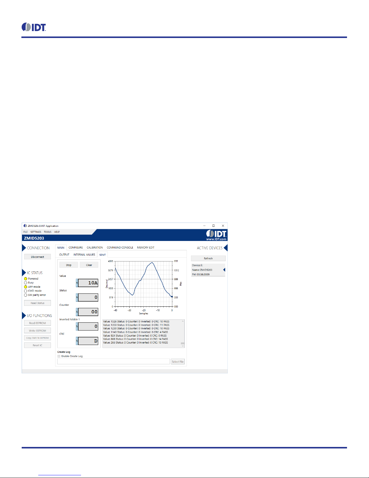
Figure 11. “OUTPUT” Tab – ZMID5203 Example
The “INTERNAL VALUES” tab displays measurements that are only accessible via OWI (see Figure 12). Therefore, all the readings are digital
register contents and not limited in terms of hardware accuracy.
Figure 12. “INTERNAL VALUES” Tab –ZMID5203 Example
ZMID520x Evaluation Kit User Manual
© 2018 Integrated Device Technology, Inc.
15
September 25, 2018
There are three controls that can be used to view and change settings on the device:
AGC Mode: Gain and integration time control –used to enable or disable the Automatic Gain Control (AGC) and the Integration Time
Control of the device. The following standard options are available in the drop-down menu:
Gain adaptation and integration time adaptation off
Gain adaptation and integration time adaptation on
Two additional options are available for the AGC Mode that are for advanced testing only. Note: Before using either of these options, contact
IDT support (see the last page for the contact information).
Gain adaptation off and integration time adaptation on
Gain adaptation on and integration time adaptation off
AGC Gain Stage. Depending on the AGC Mode, this control has different behaviors:
When the AGC is active (“Gain and integration time adaptation”is on), the value in the “ACG Gain Stage” entry field specifies the
maximum gain for gain regulation. During measurements, the box becomes read-only and displays the existing gain stage setting that
the ZMID520x is using.
When the AGC is disabled (“Gain and integration time adaptation”is off), the value in the input field specifies the selected gain stage.
Over Sampling Rate (OSR). This parameter defines the number of averaging samples per receiving channel and reduces the noise level
on the signal.
The “SENT” tab is only available when the ZMID5203 Application Module is connected to the ZMID-COMBOARD. It displays the decoded SENT
data information as shown in Figure 13.
Figure 13. “SENT”Tab (ZMID5203 only)
ZMID520x Evaluation Kit User Manual
© 2018 Integrated Device Technology, Inc.
16
September 25, 2018
2.3 Changing the Configuration Settings
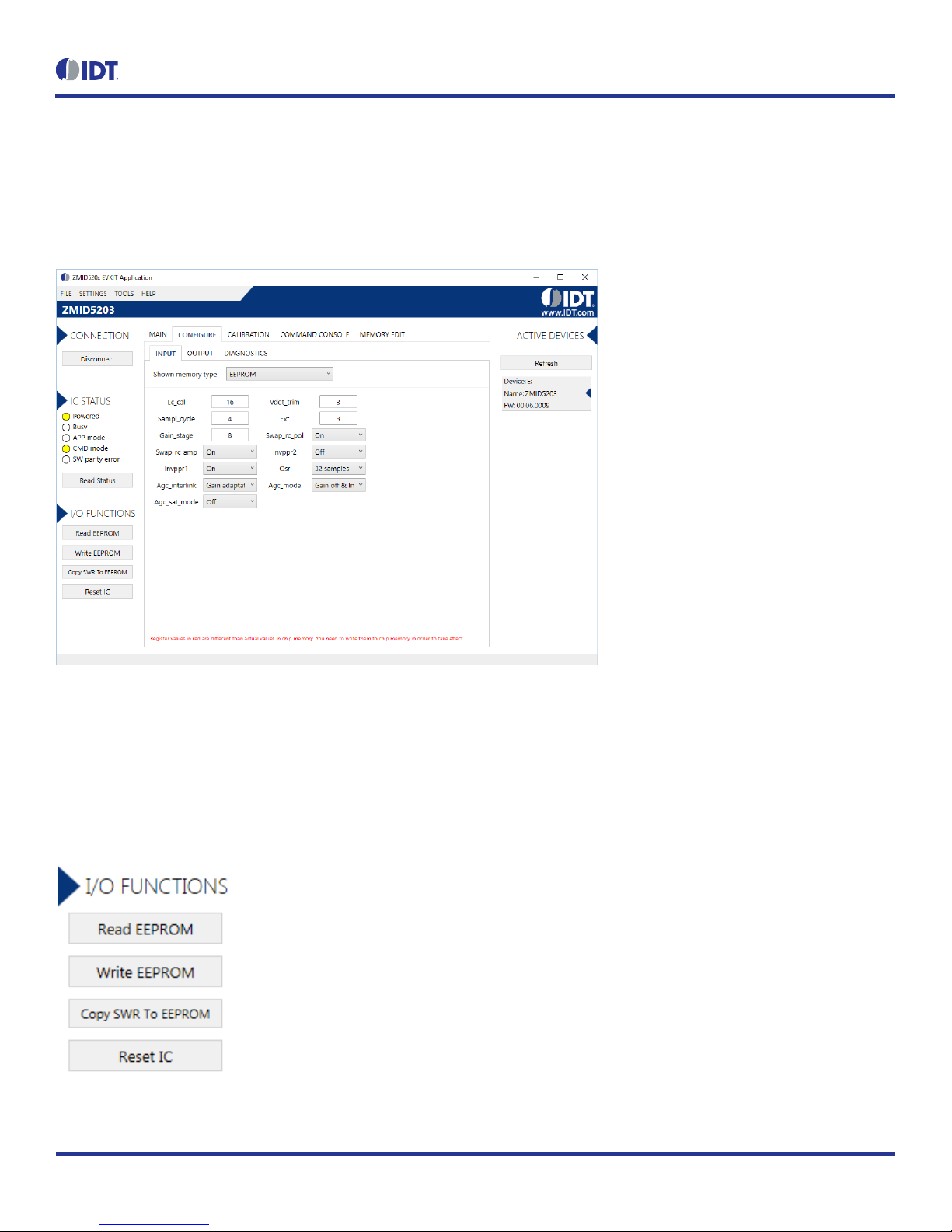
The “CONFIGURE” tab (see Figure 14) is designed to provide the user with an easy way of viewing and editing the IC configuration. Each value
represents a register or a part of a register from the internal memory of the device. The displayed memory type can be either the ZMID520x
EEPROM or the SWR memory. SWR refers to shadow registers used as the working memory for the ZMID520x, which can be temporarily
written via the GUI to the ZMID520x for development purposes.
Figure 14. "CONFIGURE" Tab –Selection of Memory Type to be Displayed
If parameters in the EEPROM memory selection have been changed, the ZMID520x must be reset after the writing process is finished for the
changes to take effect. This is done automatically after pressing the “Write EEPROM” button in the “I/O FUNCTIONS” section (see Figure 15).
This can be disabled via the “SETTINGS” menu > “Reset on Memory Write.”In the case of the SWR selection, by default, changes are
immediately written to the SWR memory of the ZMID520x. This option can be disabled via the “SETTINGS” menu > “Enable Automatic SWR
Write” (see Figure 16). Clicking the “Write SWR to EEPROM” button in the “I/O FUNCTIONS” section copies all of the current SWR settings to
the EEPROM memory of the device. This section also provides the “Reset IC” button for manually resetting the ZMID520x. The reset power
cycles the device and puts it in Command Mode. After reset, the contents of the EEPROM of the device are copied to its working memory SWR.
Figure 15. Buttons in the “I/O FUNCTIONS”Section

ZMID520x Evaluation Kit User Manual
© 2018 Integrated Device Technology, Inc.
17
September 25, 2018
Figure 16. Options on the “SETTINGS”Menu
There are three different data types shown on the “CONFIGURE” tab:
1. Numerical values are displayed in a white field (see Figure 17). If they are hexadecimal, “0x” is automatically inserted at the beginning
of the value.
2. Values with predefined multiple choices are displayed in a drop-down menu (see Figure 18).
3. Read-only values are displayed with a light blue background. They can only be selected and copied (see Figure 19).
Figure 17. Example of Numerical Values That Can be Edited
Figure 18. Example of a Drop-Down Menu with Multiple Choice Values
Figure 19. Example of Read-Only Values
Changing a value will change the font color to red (see Figure 20). This indicates that the change has not yet been applied to the actual memory
(EEPROM or SWR) of the IC. To apply the change, click the corresponding “Write…” button in the “I/O FUNCTIONS” section. If the “Reset IC”
or one of the “Read” buttons is pressed, the values will be set to represent the current settings of the device.
Figure 20. Example of a Modified Value that is Not Yet Saved to Memory
Context-sensitive pop-ups (see Figure 21), referred to as “tooltips,” provide additional information that appears briefly as the cursor hovers over
an element on the screen. The tooltips for entry fields include a brief description of the setting and the address of the internal memory register.
Figure 21. Example of Tooltip Information

ZMID520x Evaluation Kit User Manual
© 2018 Integrated Device Technology, Inc.
18
September 25, 2018
2.4 Calibration
There are three sub-tabs under the “CALIBRATION” tab: COIL OFFSET, OUTPUT RANGE, and CALIBRATION AND LINEARIZATION.
2.4.1 “COIL OFFSET” Sub-tab
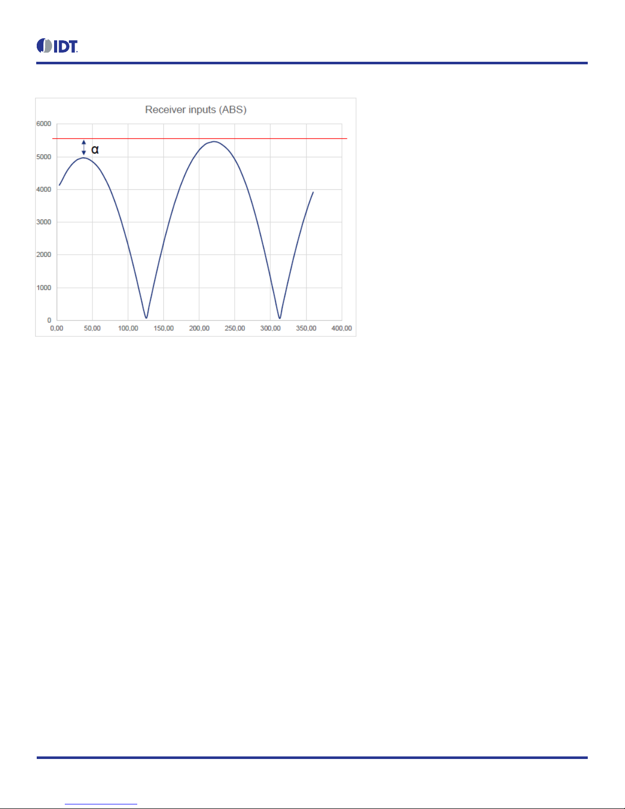
The “COIL OFFSET” sub-tab is located under the “CALIBRATION” tab (see Figure 22). It is used to compensate the offset of the signal acquired
from coils R1 and R2 connected to the ZMID520x.
Figure 22. “COIL OFFSET” Tab – ZMID5203 Example
For each of the coils, the following are displayed:
1. R1 Offset –Offset applied to the signal from the R1 coil.
2. R2 Offset –Offset applied to the signal from the R2 coil.
The GUI automatically determines which of the coils is the sine and cosine signal based on the current configuration settings. The two signals
are color coded in red and green. When the “Read” button is pressed, the current sine and cosine and their maximal and minimal values are
displayed next to the graph.
ZMID520x Evaluation Kit User Manual
© 2018 Integrated Device Technology, Inc.
19
September 25, 2018
Figure 23. Receiver Coil (ABS Value) Offset Example with Offset Compensation =
/2
To start the automatic calibration for amplitude offset, click the “Start Offset Compensation” button. The GUI will guide the user through a
sequence of instructions for performing the calibration procedure.
1. Remove the target from the coil, and press “Ok.”
2. Wait for a few seconds for the GUI to measure the offset. It will automatically continue to the next step.
3. Values for the Offset will be updated (see Figure 24).
4. Use the “Write EEPROM” button from the “I/O FUNCTIONS” section to save the new values to the EEPROM.

ZMID520x Evaluation Kit User Manual
© 2018 Integrated Device Technology, Inc.
20
September 25, 2018
Figure 24. Coil Offset Calibration Completed –ZMID5203 Example
This manual suits for next models
3
Table of contents
Other IDT Motherboard manuals

IDT
IDT P9221-R-EVK User manual

IDT
IDT ZMOD4510-EVK User manual

IDT
IDT 8A34xxx 48QFN series User manual

IDT
IDT EB4T4 Eval Board User manual

IDT
IDT 89EBPES48H12 User manual

IDT
IDT EB8T5A Eval Board User manual

IDT
IDT Tsi84 User manual

IDT
IDT 89EBPES24T3G2 User manual

IDT
IDT P9221-R-EVK User manual

IDT
IDT 5P49V5907 Manual

IDT
IDT VersaClock 3S User manual

IDT
IDT 8T49N24 Series Installation and operating instructions

IDT
IDT EB-LOGAN-23 User manual

IDT
IDT ZSSC4151 User manual

IDT
IDT P9242-R-EVK User manual

IDT
IDT 89EBPES16T4G2 User manual

IDT
IDT Tsi382 LQFP User manual

IDT
IDT 89EB-LOGAN-19 User manual

IDT
IDT 89EBPES12N3 User manual

IDT
IDT 8T49N240 User manual


